11. input devices
Input devices are components that gather data from the external environment and convert it into signals that a microcontroller can process. They play a crucial role in bridging the gap between real-world phenomena and digital systems, enabling data collection and interaction between these. For more details on input devices, you can visit our group page.
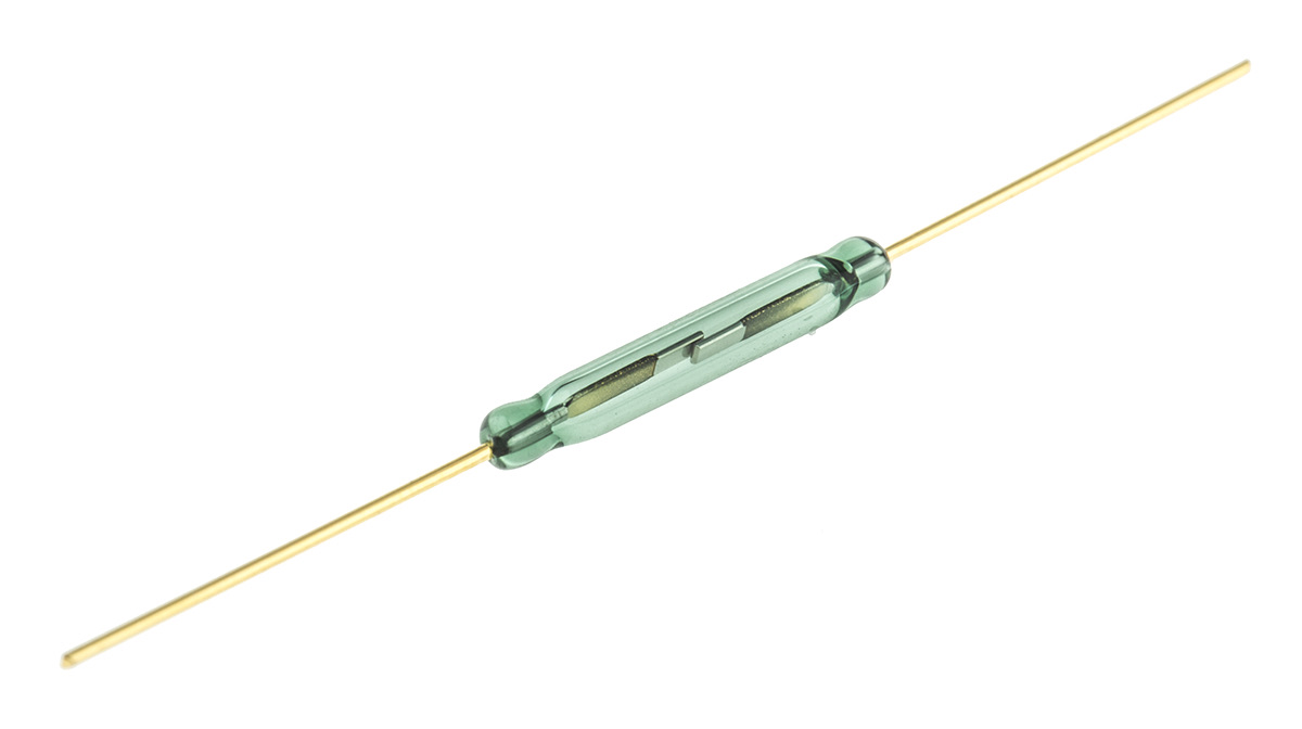
Reed switch
I decided to use a reed switch, a type of sensor that detects the presence of a magnetic field. This sensor consists of two metal reeds sealed inside a glass tube, when a magnetic field is nearby, the reeds become magnetized and either come into contact or separate, depending on the configuration. This translates into opening or closing the electrical circuit. The signals read from the switch are digital, indicating either an on (1) or off (0) state.
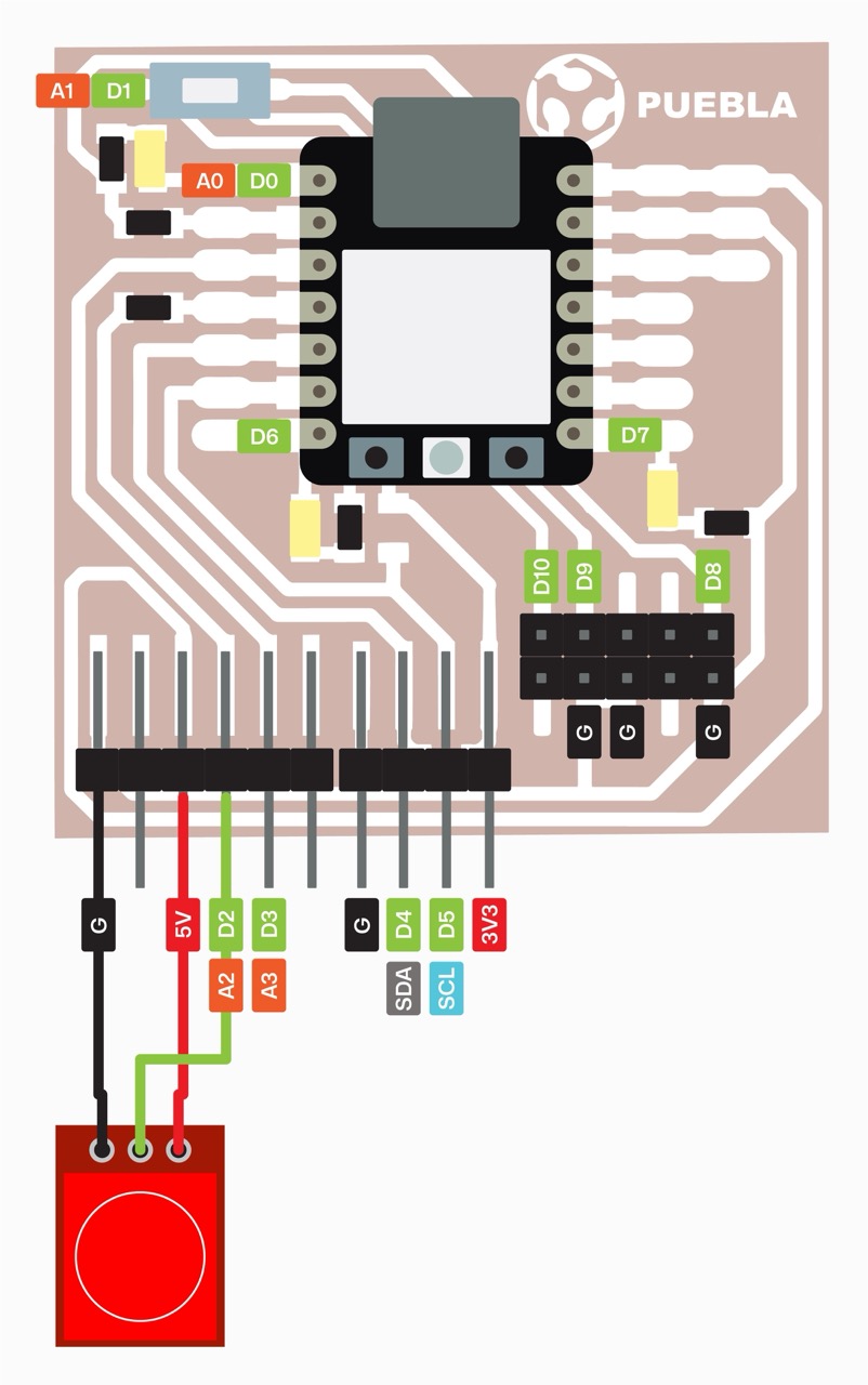
Schematic
I will be using the Xiao RP2040 we made in week 4. This board already has some embedded LEDs that will be helpful for demonstrating the usage of the reed switch.
I will be following this schematic to connect the reed switch to my board.

Code
For the code, I started by declaring the pin where the reed switch will be connected, as well as the LED pin. Then, under void setup, I set the reed pin as an input and the LED pin as an output. Finally, under void loop, I created a conditional statement: if the reed state is low, the LED will turn on; otherwise, it will be off.
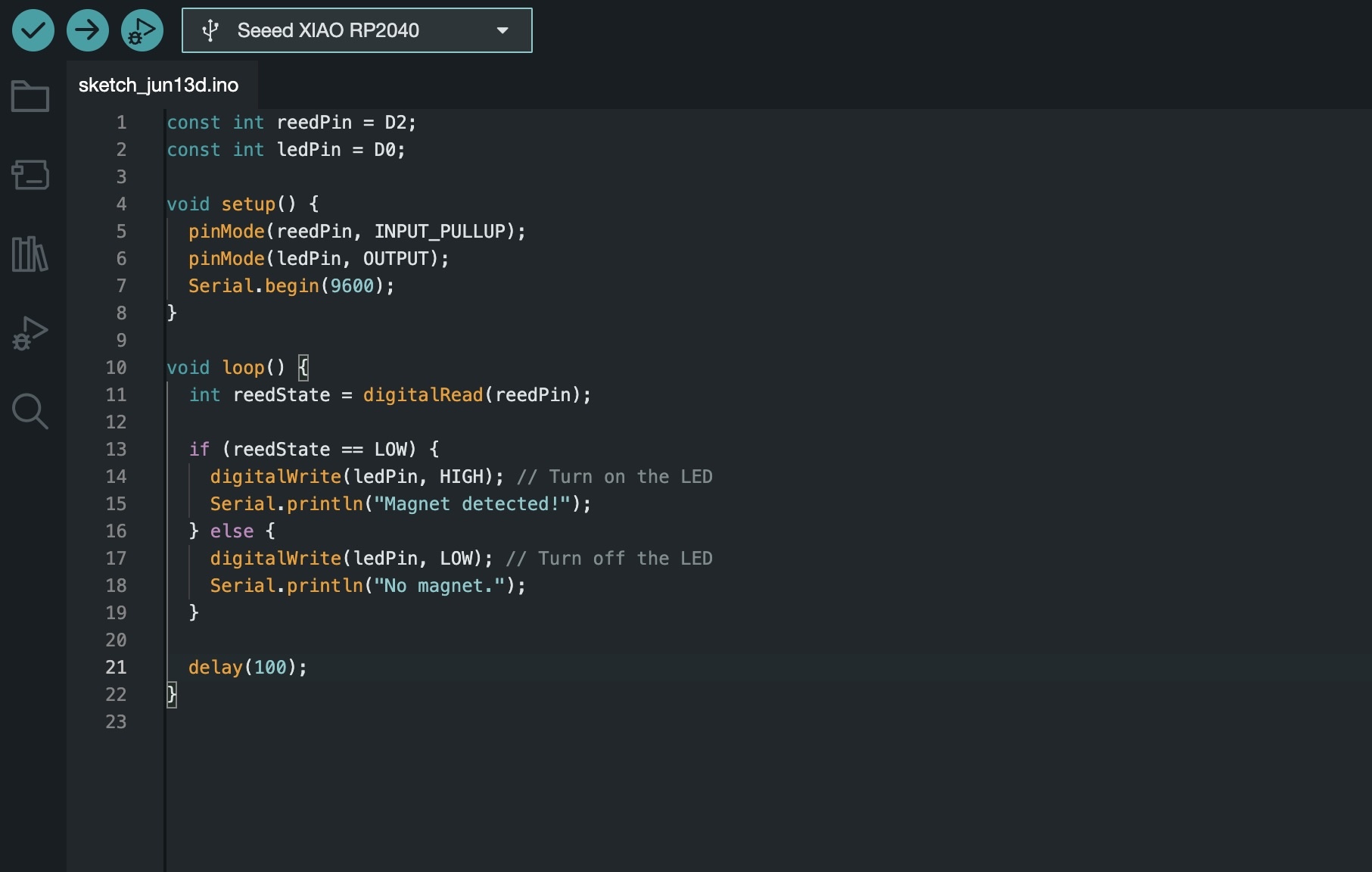
Here you can see the code in action, turining on the LED when the magnet is close to the reed switch.
Observations:
Recently, I came across some lamps that are turned on and off using a small magnetic ball. It amazes me how simple yet innovative these designs are, and I'm excited to learn about different components and technologies that I can incorporate into my own projects.
Touch sensor
A touch sensor is an input device that detects physical touch or proximity. It converts this action into an electrical signal that can be read and processed by a microcontroller. Like the reed switch the signals read from the touch sensor are digital, indicating either an on (1) or off (0) state.
Schematic
Code
To start, the touch sensor pin and the LED pin are declared. Then, the code configures the touch sensor pin (D2) as an input and the LED pin (D0) as an output, and initializes serial communication. In the loop function, it continuously reads the sensor's state. If the sensor detects a touch (indicated by a HIGH signal), the LED is turned on and "touched" is printed to the serial monitor. If no touch is detected (indicated by a LOW signal), the LED is turned off and "not touched" is printed.
