final project
First ideas for final project
I consider myself to be a very indecisive person which has made it a challenge to choose a final project within a limited timeframe. My first two choices are the following:
- I have a lot of trouble waking up so I was thinking about designing a product that could help me wake up. There are some existing alarm clocks that wake you up with light in order for it to emulate the natural process and for it to be less invasive. I was thinking of designing something similar but adapted to my own specific needs.
- My second choice is continuing developming a collaborative project initiated with three friends last year. This project involves creating an add-on for pencils, pens, or drawing tools, aimed at guiding users to express their emotions through art. Due to time restraints and lack of knowledge on coding and sensors we were not able to finish this project with a fully functional prototype. It would be a challenge given that the electronics would have to be compacted to fill a small area and the design would also have to be very efficient.
I prefer the second idea, I see it as a project with significant potential for growth. However, my concern lies with its size, as accommodating the electronics within a compact space will be challenging.
Inspiration
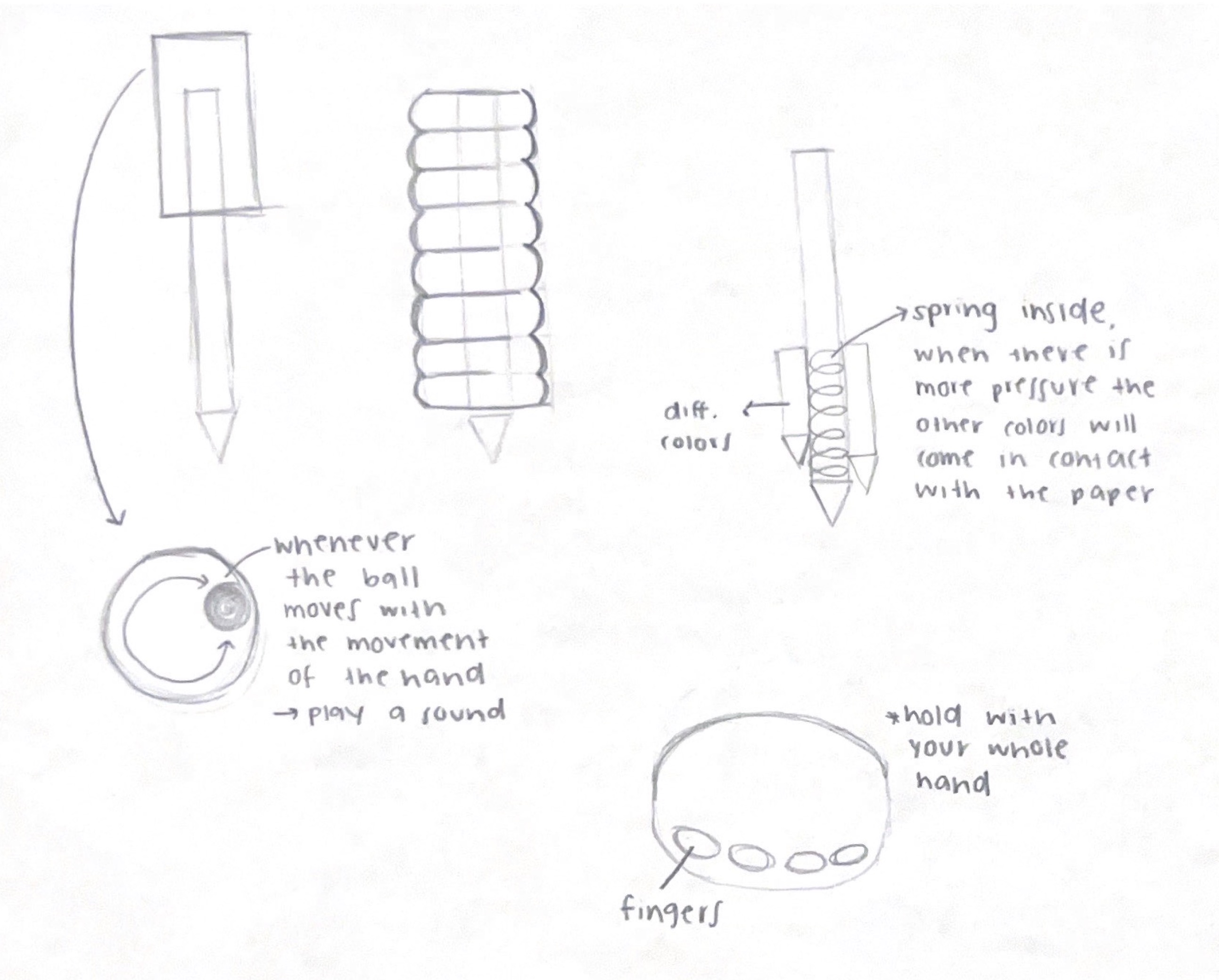
First sketches
pressure
movement
sound
ink
colors
thickness
How will the device guide the user to express their emotions?
To start, there are some biological indicators that can provide insights into our emotional states. I want this device to be able to detect the emotional state of a person and depending on that to guide the user into expressing what they are feeling.
Some of these biological indicators are the following:
- Heart rate variability: when we experience intense emotions such as fear or excitement, our heart rate tends to increase. On the other hand, feelings of relaxation or calmness may result in a slower heart rate.
- Respiration Rate: when we are stressed or anxious our breathing becomes shallow and rapid. On the contrary, when we are relaxed or at ease, our breathing tends to be slower and deeper.
- Body Temperature: in some cases, feelings of stress or anxiety may result in a slight increase in body temperature due to physiological responses.
How will it work?
Data Collection:- The user holds the device for a few seconds
- During this time, sensors gather data about the user's heart rate variability, respiration rate, and possibly body temperature
- The device analyzes this data to determine the user's emotional state
- Once the emotional state is determined, the user selects a drawing tool
- When ready, the user presses play
- The device will guide them through expressing their emotions using visual cues like lasers, hand movements (possibly through weighted feedback), sounds, and pressure sensitivity
Shift in project
During the development of the pen project, I encountered several challenges. Achieving the exact vision I had in mind proved to be quite complicated, and finding ways for the pen to effectively help express emotions was particularly challenging. Although it's a project I'm willing to continue developing, I've decided to redirect my energy toward a new project due to time constraints.
New Inspiration:
Applications and Implications
I have recently become very interested in a concept called "Calm Technology" or "Calm Design." This approach suggests that technology shouldn't demand all of our attention, only some, and only when necessary. It is guided by the following principles:
- Technology can communicate without needing to speak.
- The right amount of technology is the minimum necessary to solve the problem.
- Good design allows people to accomplish their goals with the least amount of steps.
- Calm technology enables people to achieve their goals with minimal mental effort.
- A person's primary task should not be computing, but being human.
(Case, 2016)
Building on the concept of Calm Technology, I decided to analyze how we work and the fast-paced lifestyle many of us lead. This often results in high anxiety and stress levels, which diminish our quality of life and hinder our concentration and productivity. I wanted to create something that could help us become more aware of our bodies and reduce these emotions.
Breathwork for Stress Reduction
After some research, I discovered the importance of breathing in regulating our bodies.
“Research shows that different emotions are associated with different forms of breathing, and so changing how we breathe can change how we feel. For example, when you feel joy, your breathing will be regular, deep and slow. If you feel anxious or angry, your breathing will be irregular, short, fast, and shallow. When you follow breathing patterns associated with different emotions, you’ll actually begin to feel those corresponding emotions. Changing the rhythm of your breath can signal relaxation, slowing your heart rate and stimulating the vagus nerve, which runs from the brain stem to the abdomen, and is part of the parasympathetic nervous system, which is responsible for the body’s “rest and digest” activities (in contrast to the sympathetic nervous system, which regulates many of our “fight or flight” responses). Triggering your parasympathetic nervous system helps you start to calm down. You feel better. And your ability to think rationally returns” (Bradley et al., 2020).
There are various breathwork techniques that have been proven to reduce stress and anxiety levels, improving both physical and mental health. For this project, I decided to focus on the 4-7-8 breathing technique, which involves inhaling for 4 seconds, holding your breath for 7 seconds, and exhaling for 8 seconds. It is recommended to start with 4 full breaths, which takes about 1 minute and 16 seconds, and gradually work up to 8 full breaths, totaling 2 minutes and 32 seconds (Gotter, 2018).
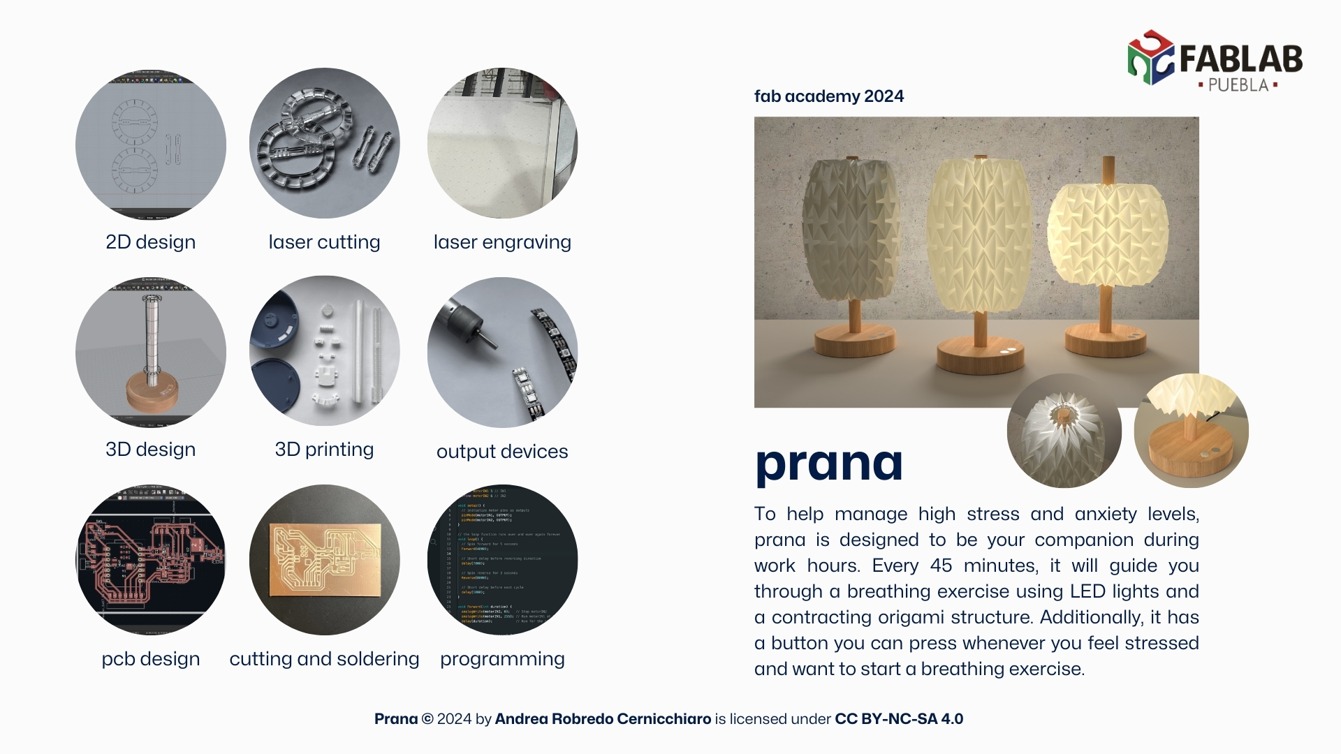
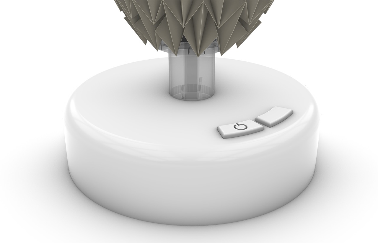
To implement this, I came up with the idea of making a desk lamp that emulates breathing every 45 minutes. The purpose is to catch the user’s attention and remind them to take 3 minutes to focus on their breathing. This duration was chosen based on the time it takes to complete 8 full breaths and the additional time needed to recognize the visual cue and prepare for the breathwork.
- Communicating non-intrusively: The lamp uses subtle light cues to signal when it’s time to breathe, without disrupting the user's current activity.
- Providing the minimum technology needed: The lamp’s simple design and functionality are focused solely on aiding breathwork, avoiding unnecessary features.
- Enabling goal accomplishment with minimal effort: The lamp helps users manage stress and improve focus with a gentle reminder, making it easy to integrate into daily routines without significant mental effort.
- Allowing the primary task to be human: The lamp supports users in taking a moment to breathe and relax, prioritizing well-being over continuous engagement with technology.
This product embodies the principles of Calm Technology by:
Prototyping
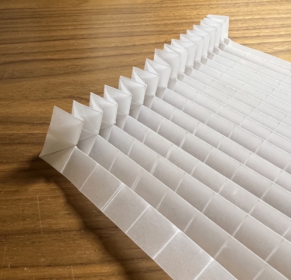
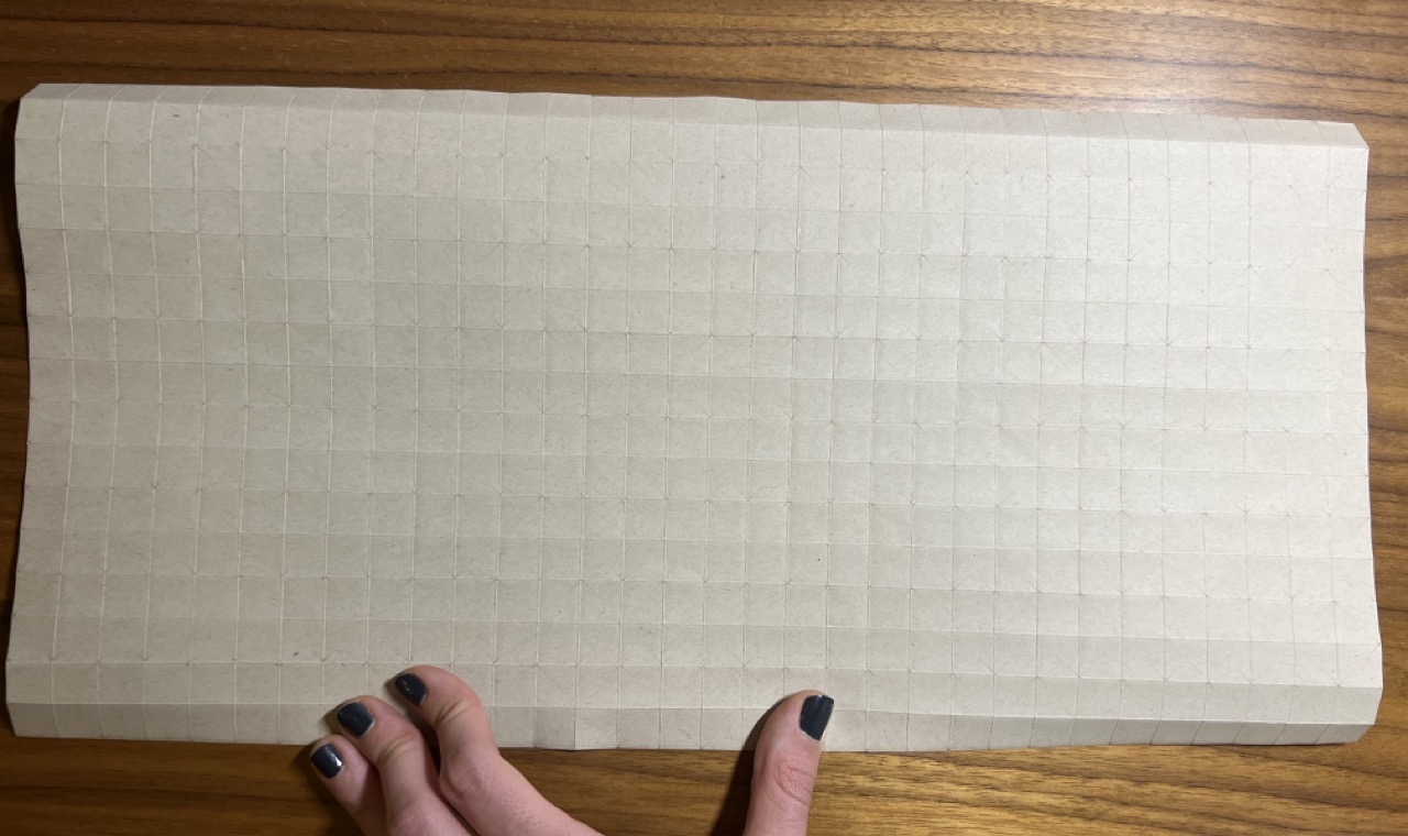
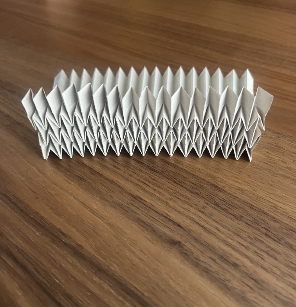
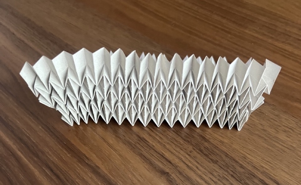
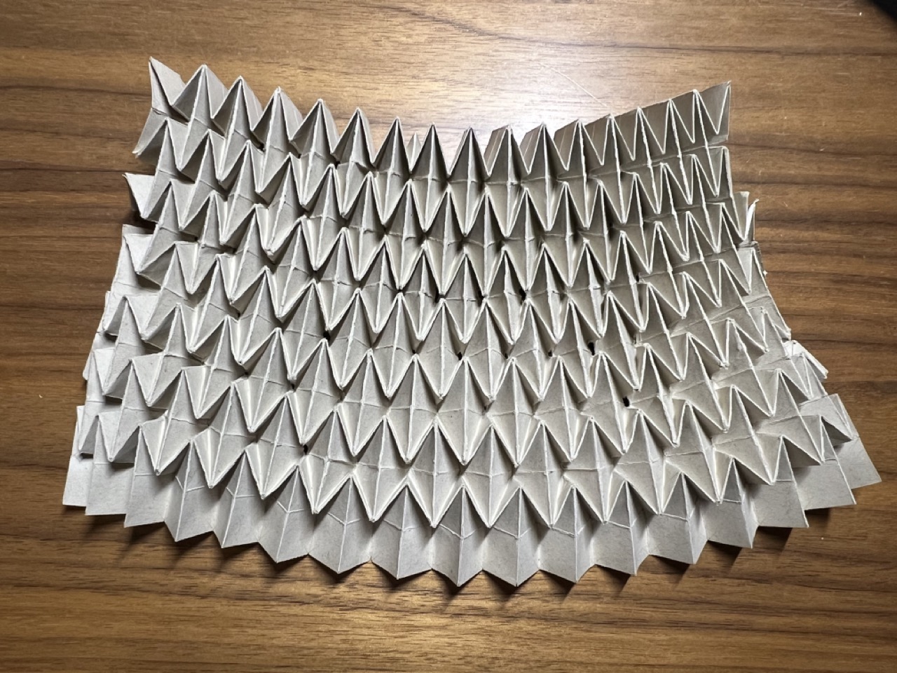
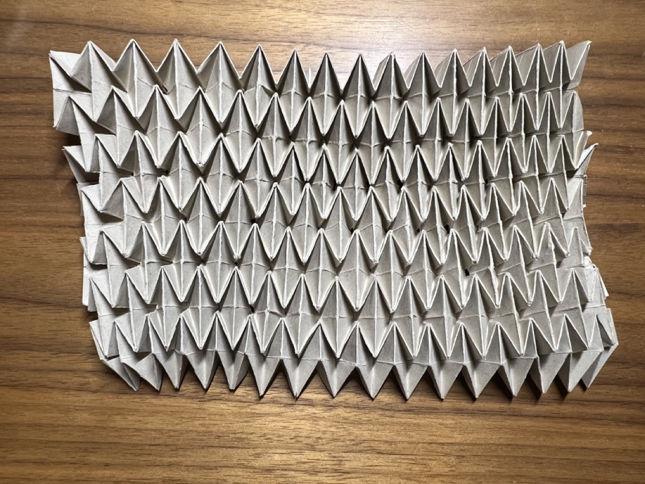
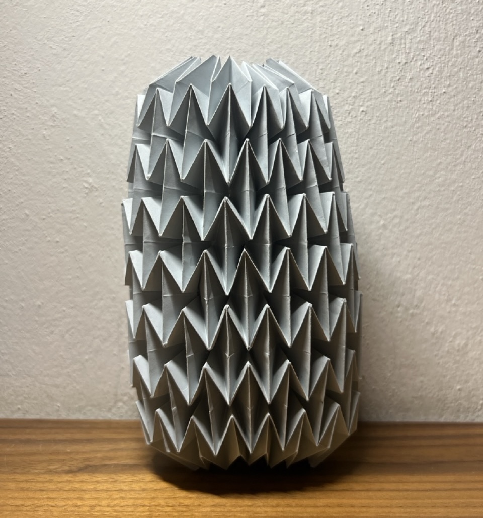
I have always been fascinated by the potential of origami, so I began researching various origami projects to get inspired and evaluate possible mechanisms.
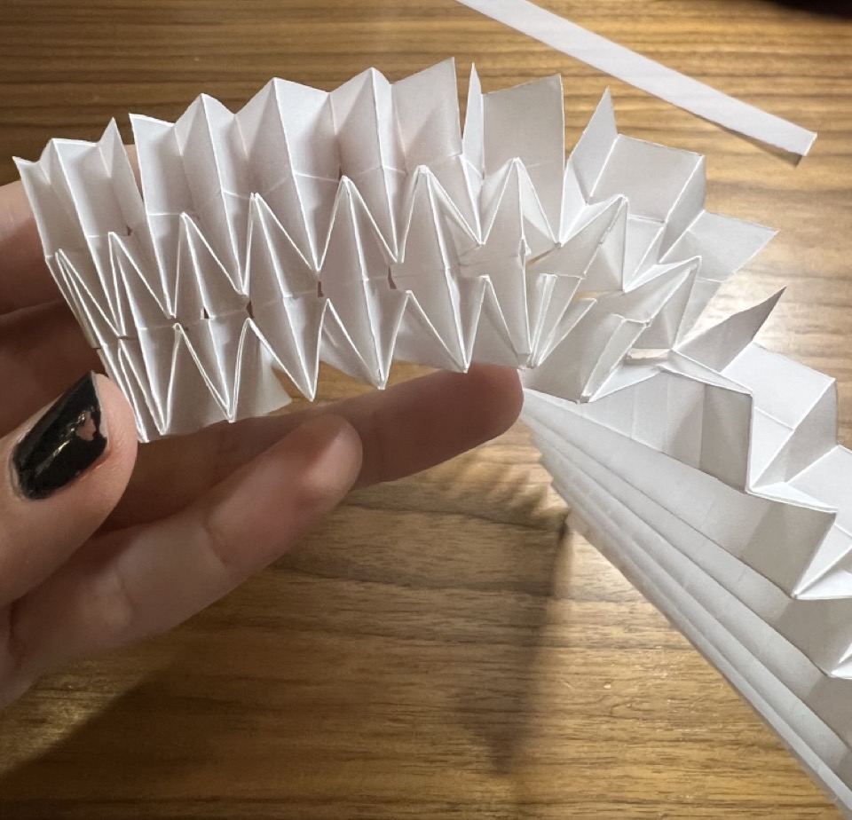
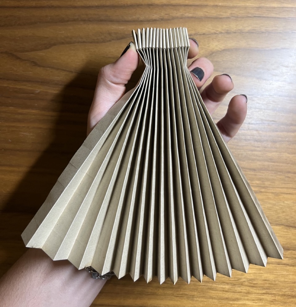
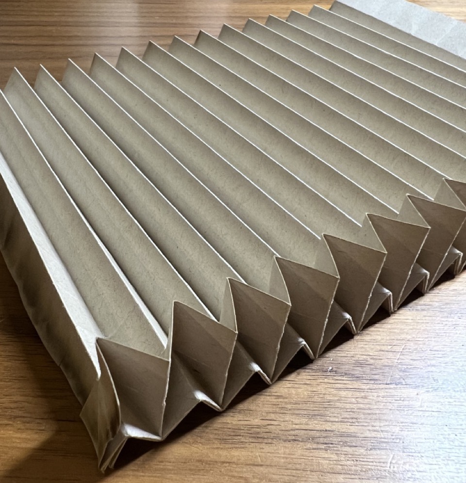
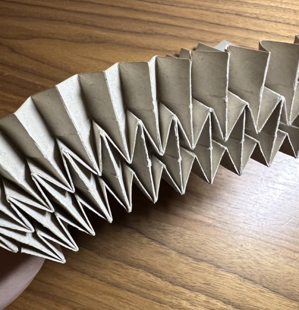
To start, I decided to create a quick prototype using a video tutorial on YouTube and regular printing paper. This initial prototype was made to experiment with the mechanism and test if the ideas I had in mind would work. After completing this prototype, I found that the movement of the paper worked perfectly for emulating breathing.
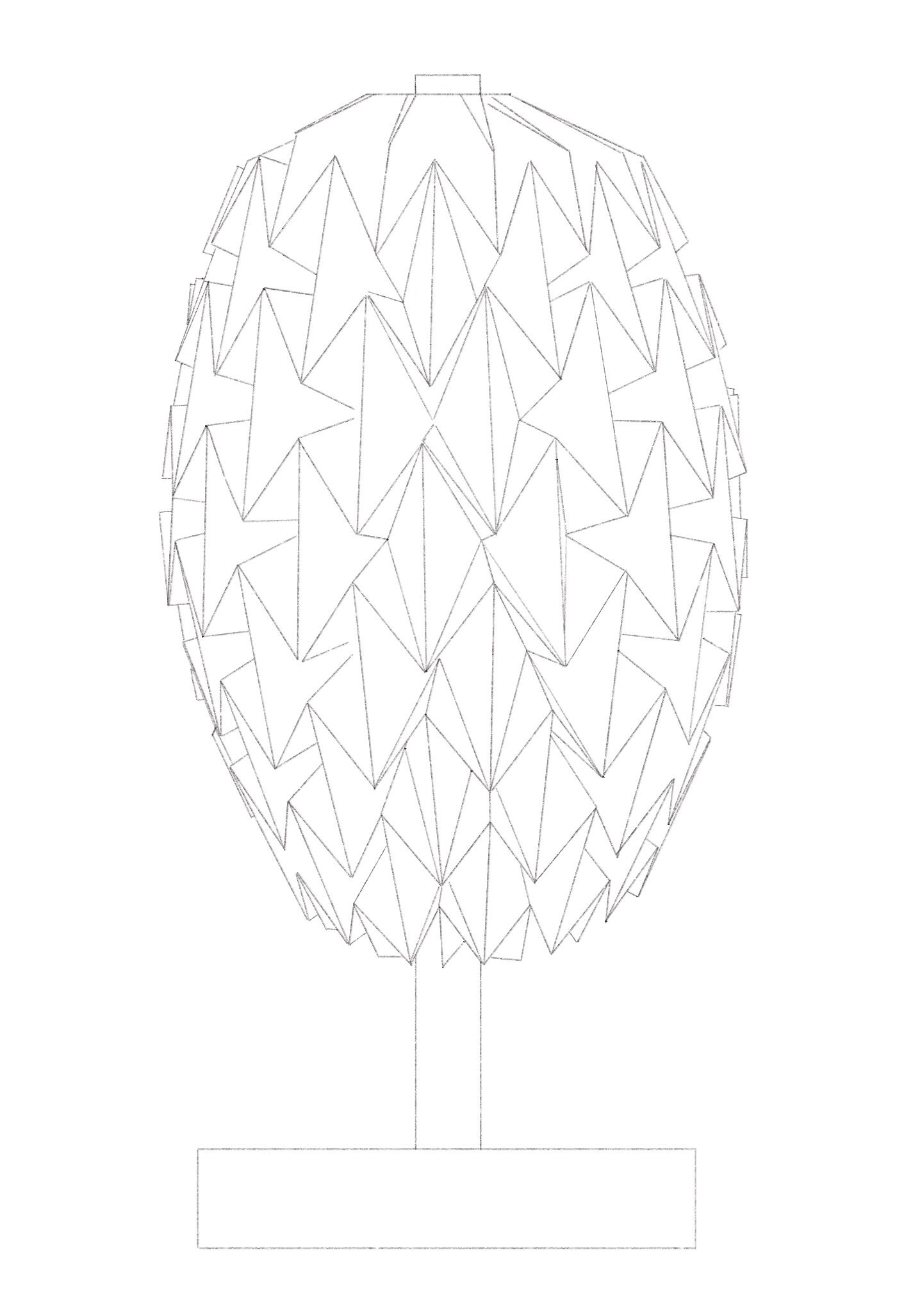
I began sketching some ideas to incorporate the origami to a lamp design, this is the selected design.
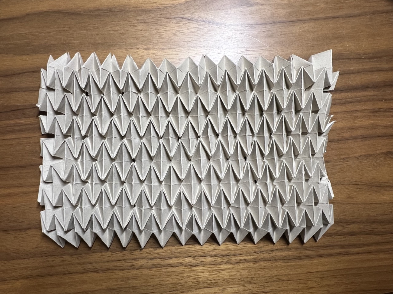
I then began to make a second prototype with the actual dimensions (40x20 cm) using Albanian paper due to its translucency. However, I encountered an issue, the paper started to tear with the continuous folding.
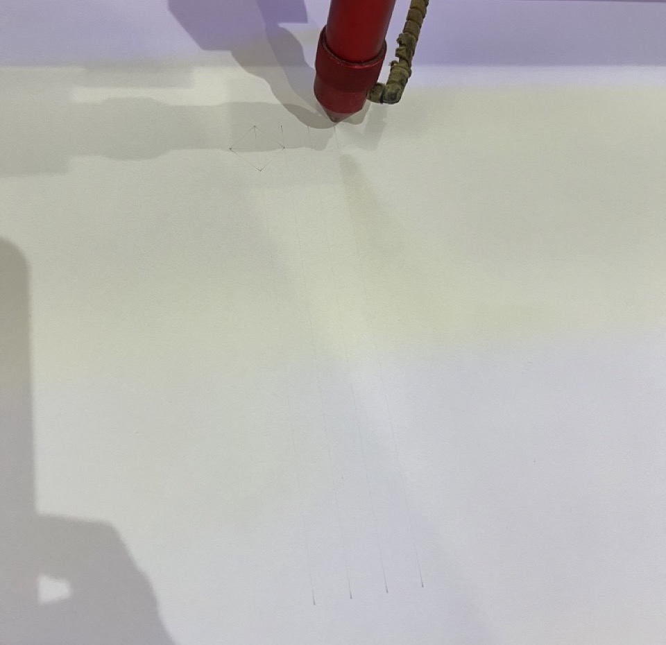
Given the time-consuming nature of the manual process, I decided to speed it up by trying two fabrication methods. First, I used a laser cutter to engrave the folding pattern, allowing for faster and more precise production of the origami structure. Second, I experimented with 3D printing the pattern using TPU filament.
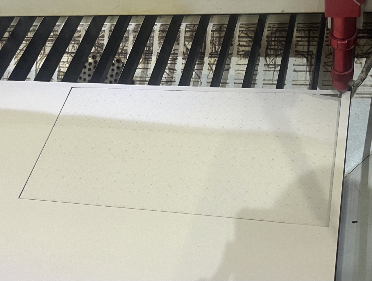
Laser cutting and engraving
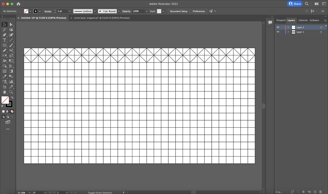
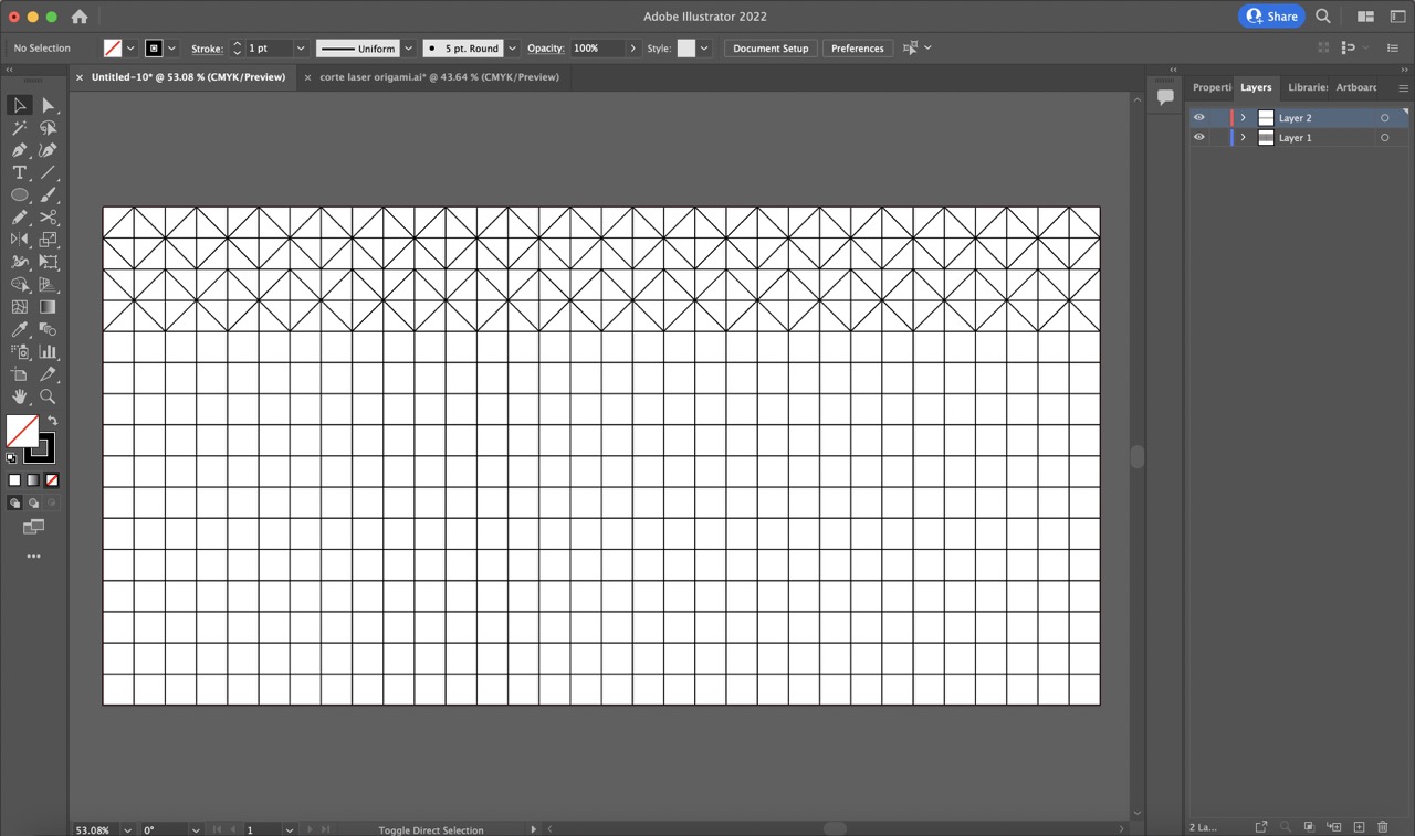
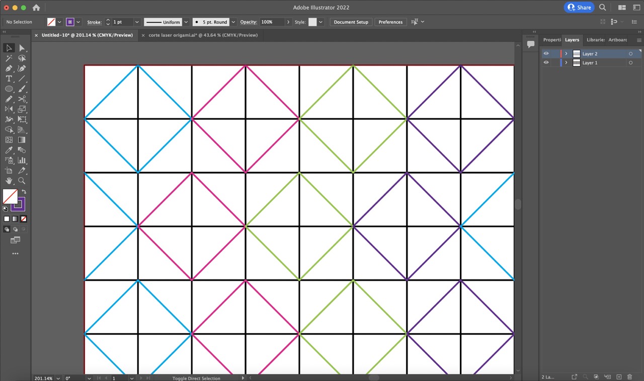
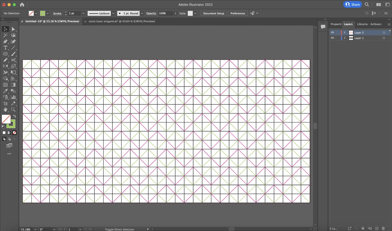
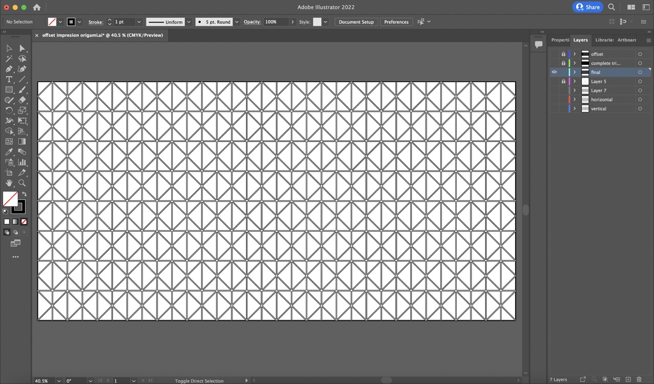
To start, I created an artboard in Illustrator with the desired dimensions (400 x 200 mm). I then traced lines corresponding to the origami folds: 17 horizontal lines to create 16 equidistant sections and 33 vertical lines to create 32 equidistant sections. Next, I designed the first pattern on the first two rows and the second pattern on the following two rows. Finally, I copied these patterns to their corresponding rows to complete the design.


Then I bought paper in different thicknesses to test engraving the pattern with the laser cutter. I chose 90g, 118g, and 216g papers and began running tests. After some experimentation, I found the correct parameters: 150 speed and 10 power.
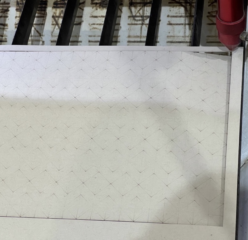
During the first few attempts, I noticed that the vertices of the rhomboid pattern had small holes. This was because the vector trace was made up of individual rhomboids, causing the laser cutter to pass over the same point twice and create holes. To fix this, I modified my vectors to be continuous zigzag lines.
After making this adjustment, these were the results:
90g:
The holes are apparent

118g:
The holes are minimal

216g:
There are no holes

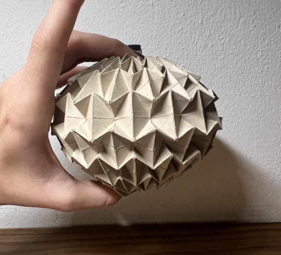
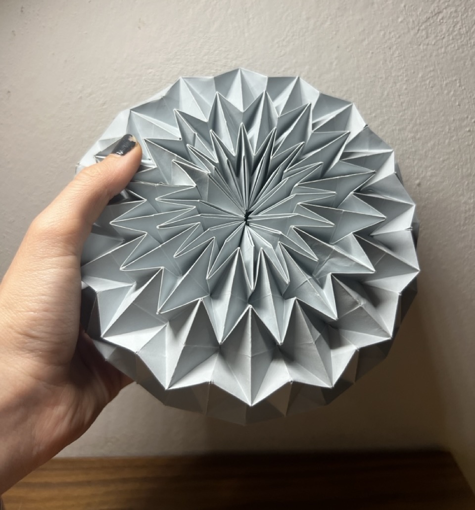
I opted to use the 118g paper for the full-scale prototype since the 216g paper was too thick for origami. Here is the process and the final result:

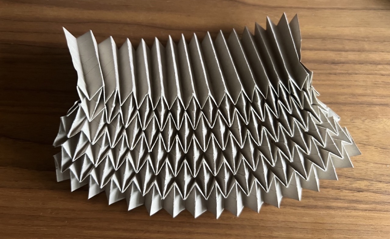

Observations:
- I would like the origami to be taller. The current prototype is 13 cm, but I would like the total height to be 20 cm.
- Although the holes at the vertices were minimal after engraving the pattern with the laser cutter, they became more apparent with continuous folding. The type and thickness of the paper likely influenced these holes as well.
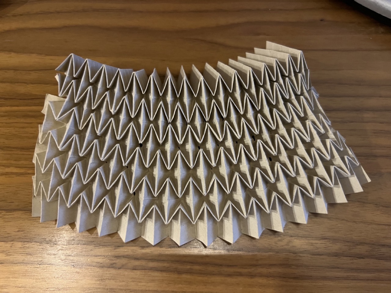
This is the prototype with the modified dimensions (60 x 30 cm).
3D printing TPU filament
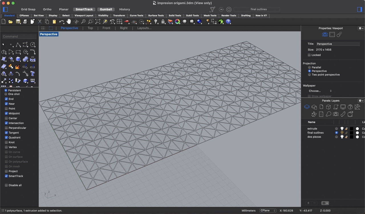
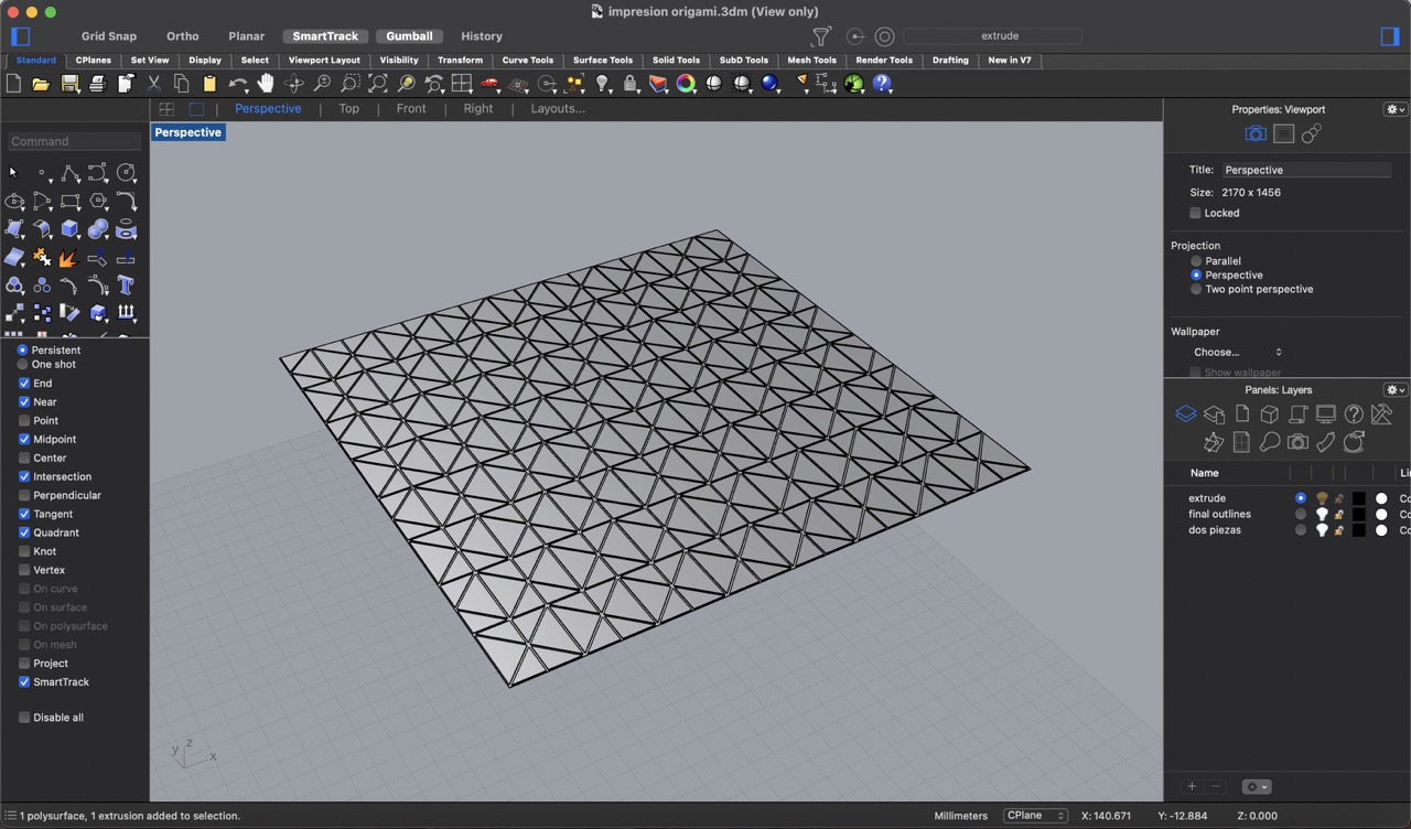
To start, using the same Illustrator file, I traced each of the triangles and then offset them by 0.5 mm. In total, the width of the folding segments will be 1 mm.
Next, I imported this file into Rhino. I selected all of the triangles and extruded them to 0.4 mm, and the rectangle to 0.2 mm. Since the printing area of the 3D printer is 30 x 30 cm, I had to cut the pattern in half to fit.
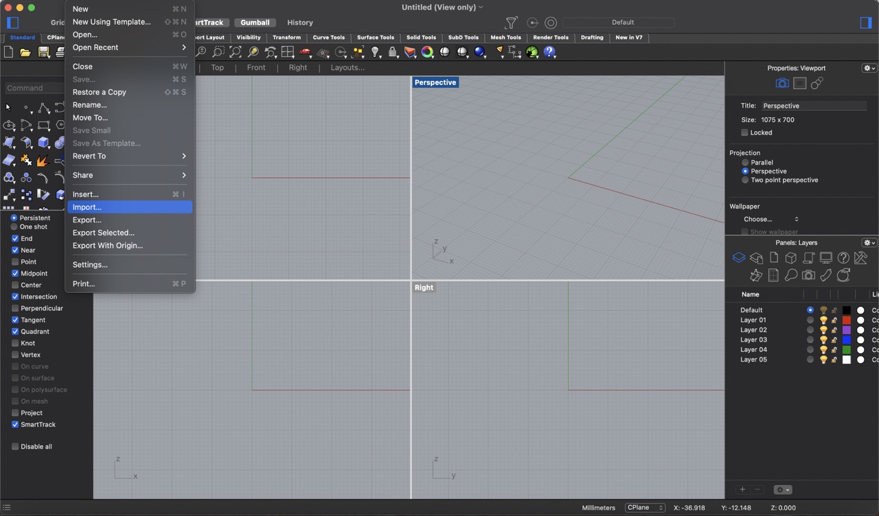
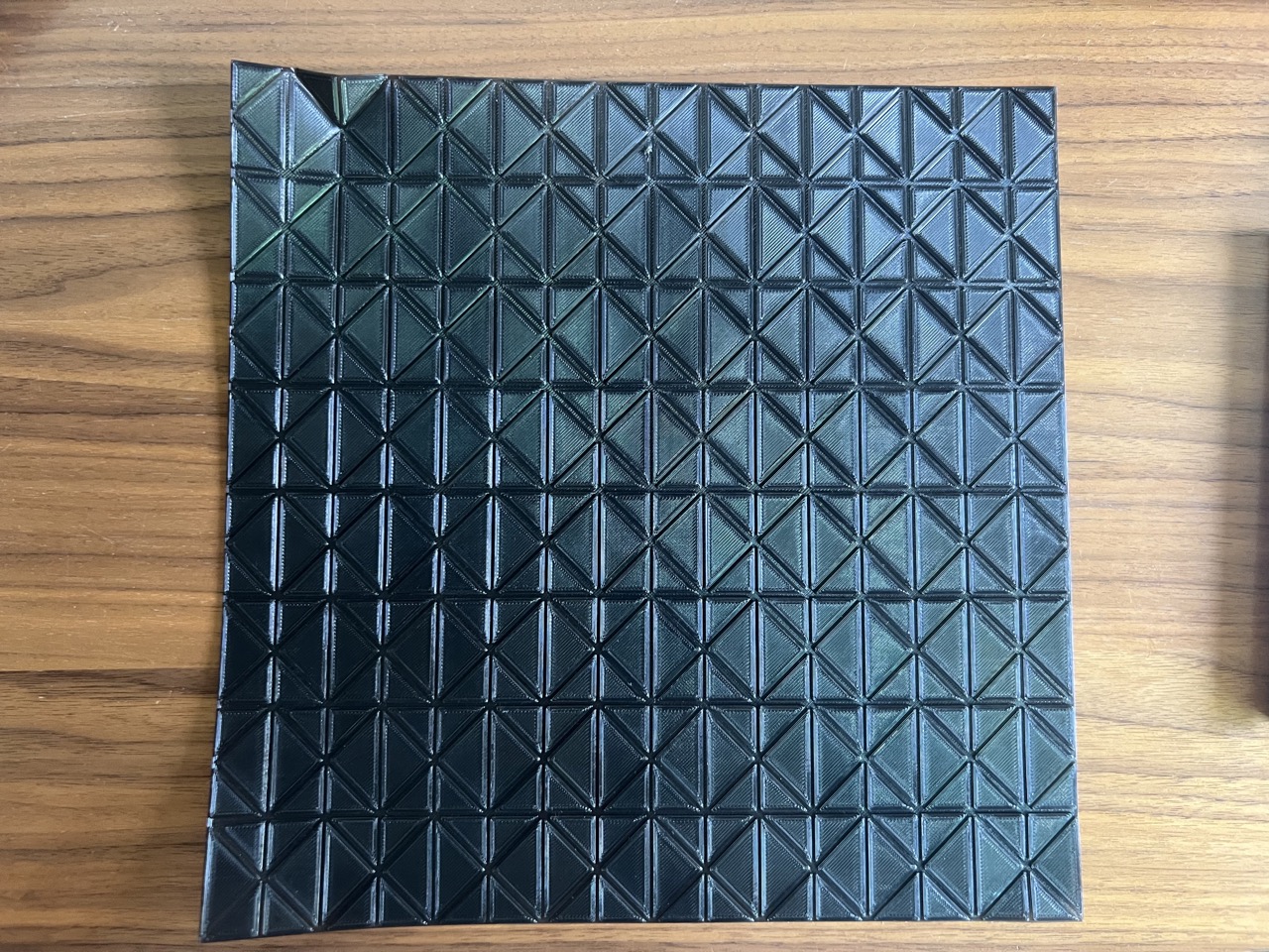
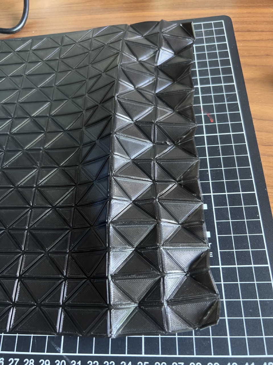
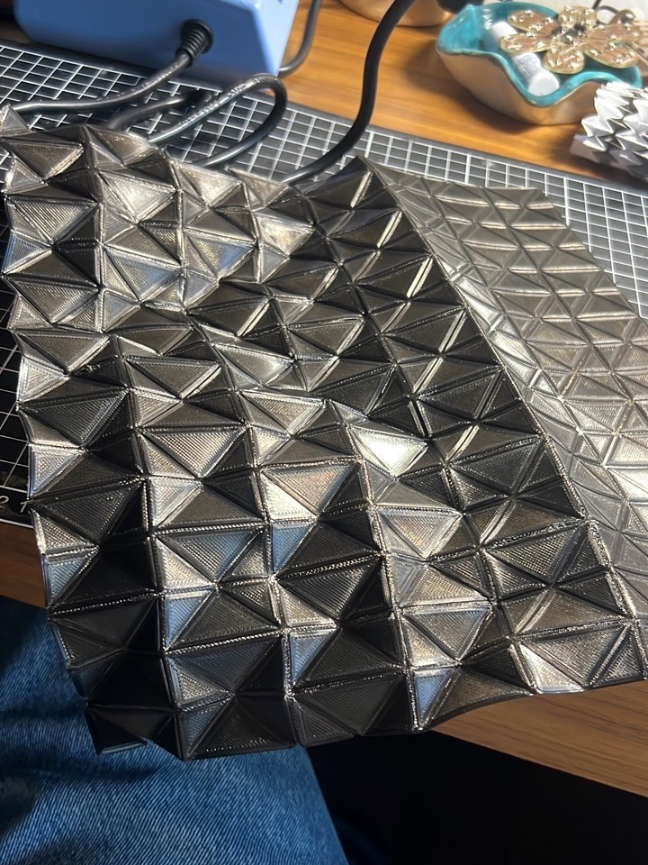
I then exported the file into .stl format and made the necessary modifications in Cura slicer for the TPU filament.
This was the final printed result. Although it is possible to fold it, the shape does not stay folded.
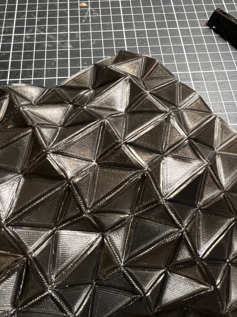
To fix this, each of the folds was marked with the help of a lighter. The fold was made to the corresponding side, and heat was applied for the shape to stay that way.
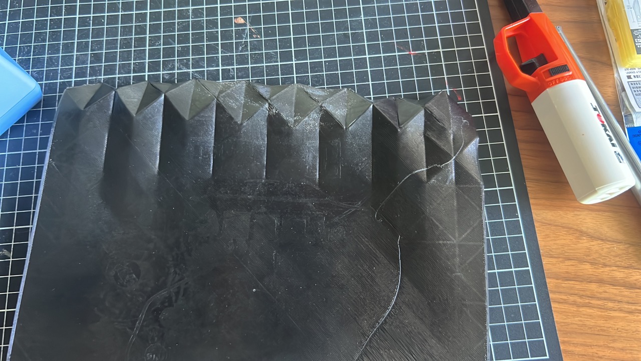
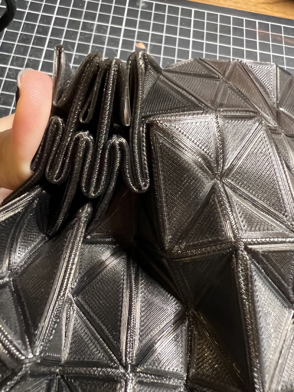
Observations:
- The printed sheet should be thinner because when the pattern is folded, it becomes very thick and it is complicated to keep the desired form.
- The process was very time-consuming.
- I am not sure that even with a thinner sheet, the mechanism would work effectively.
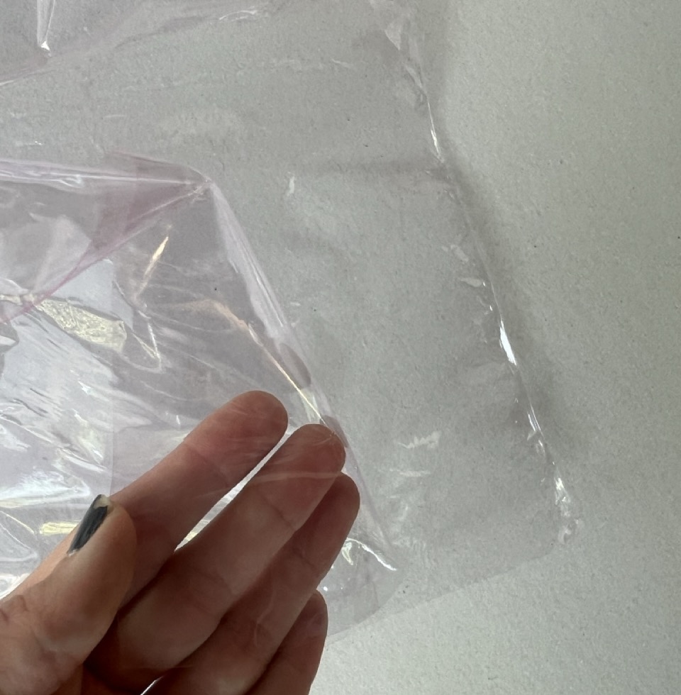
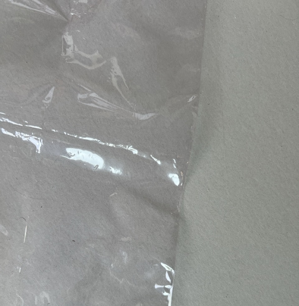
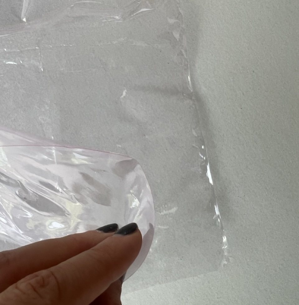
After this, I got the idea of 3D printing on top of a heat-shrinkable material. The plan is to print the pattern, fold it accordingly, and then apply heat to keep the folded shape of the origami structure. For this, I thought of using the wrapping plastic used for gift baskets, which is made of PVC.
Mechanism
For this project to work, the mechanism is crucial as it will enable the origami structure to expand and contract, mimicking the breathing exercise. This will be achieved using internal wires and a motor to move the top and bottom of the origami structure as needed.
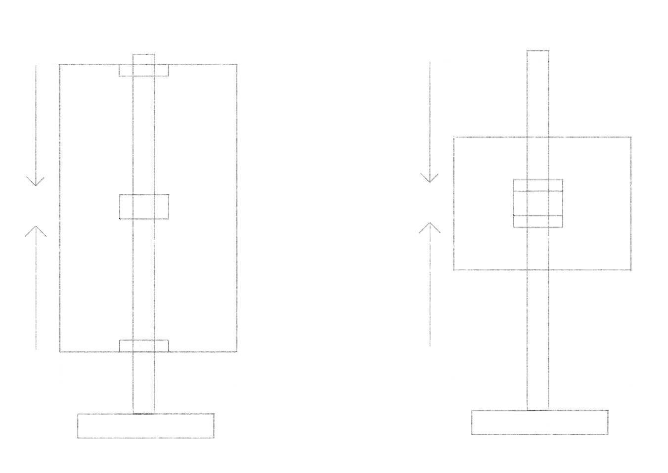
First Idea
Red wire: Starts from the bottom, moves up to the top, then goes inside a central tube down to the base where the motor is located.
Blue wire: Simply goes down from the top to the base and connects to the motor.
Second Idea
Red wire: Comes to the center and then goes straight down. This might be tricky due to potential high friction, making it difficult for the origami structure to move smoothly.
Blue wire: Remains the same as in the first idea.
Comments:
- In both ideas, the cables would be exposed when the origami contracts.
- Each idea relies on a single cable to move the top and one for the bottom, which might lack stability.
Third Idea
After analyzing the initial proposals and considering their limitations, I decided to develop a new mechanism that addresses these issues and offers improved functionality. This revised proposal aims for better stability and a more effective movement of the origami structure.
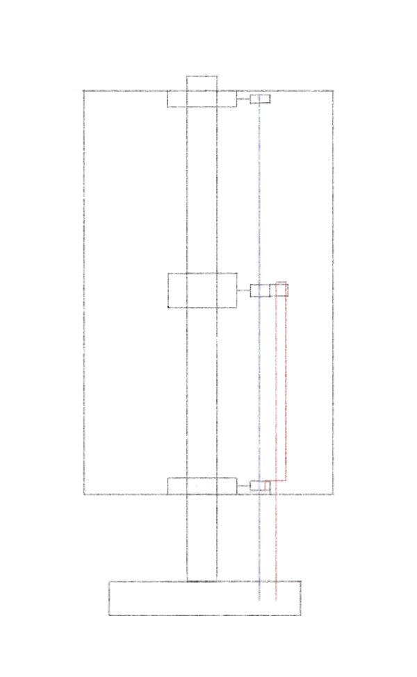
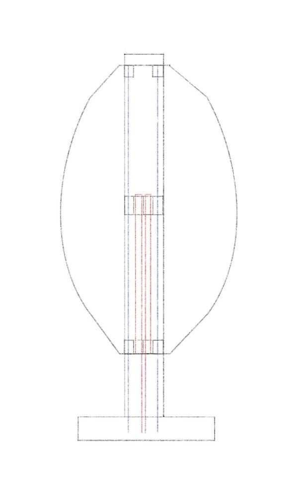
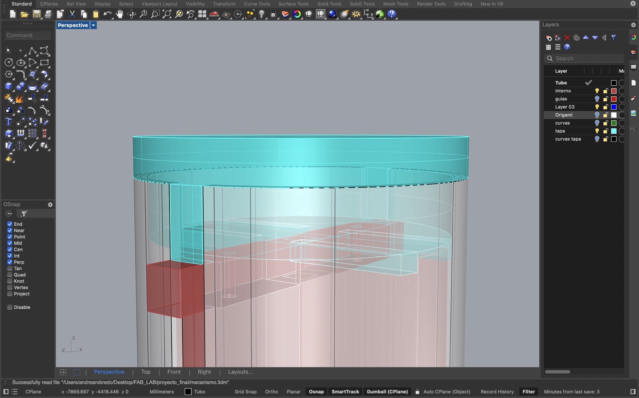
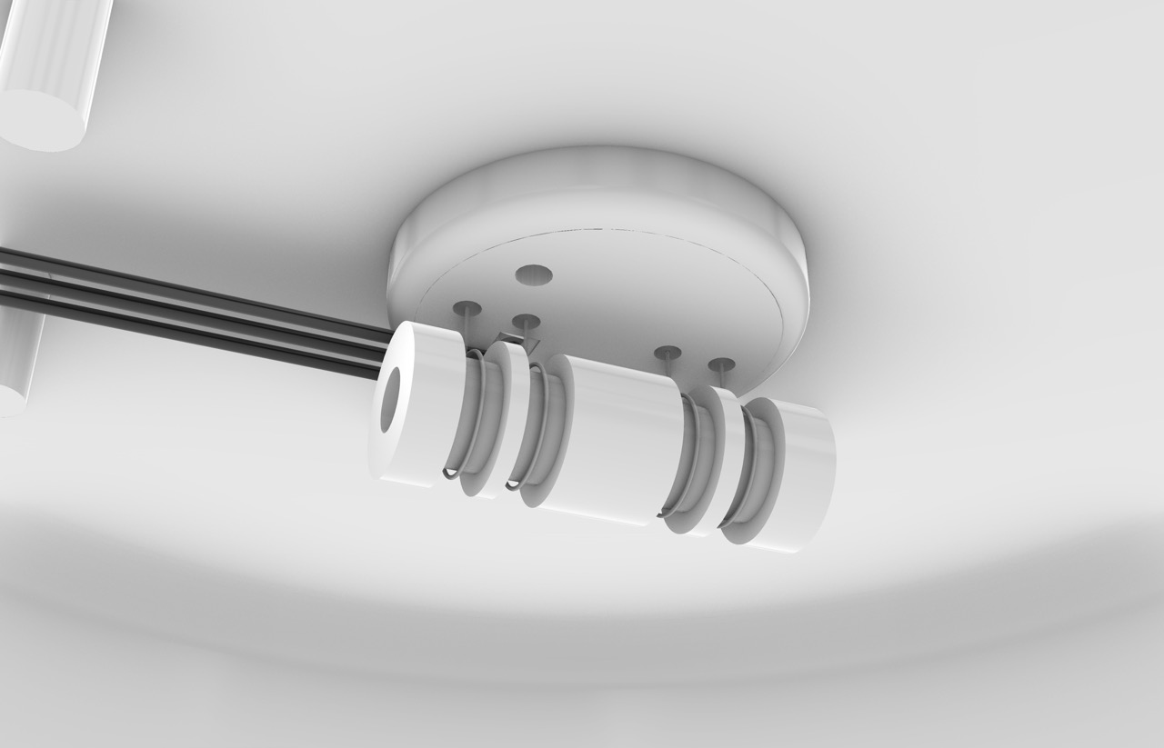
This idea focuses on having all of the wires inside a tube, ensuring they are not visible. The entire mechanism will be housed within the tube, which will have two side slots where a piece will be attached to the origami structure. This rail system will allow the mechanism to expand and contract the origami smoothly. To ensure stability and correct movement, the mechanism will be mirrored on both sides.
Red wire: It follows a similar path to the previous idea, but with reduced friction. It starts at the bottom, connected to the motor, then goes up to the middle, and comes back down to where the origami structure is attached.
Blue wire: It flows from the top to the bottom, remaining unchanged from the previous designs.
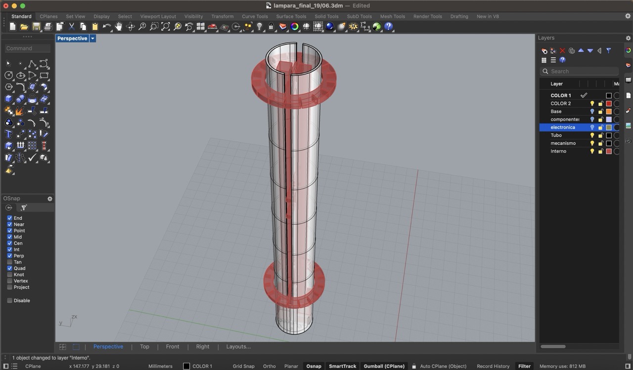
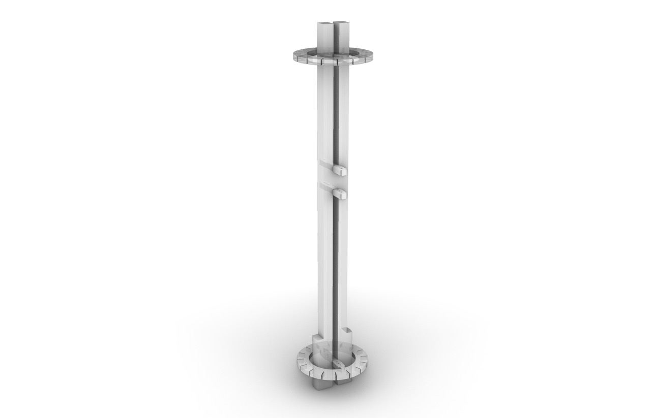
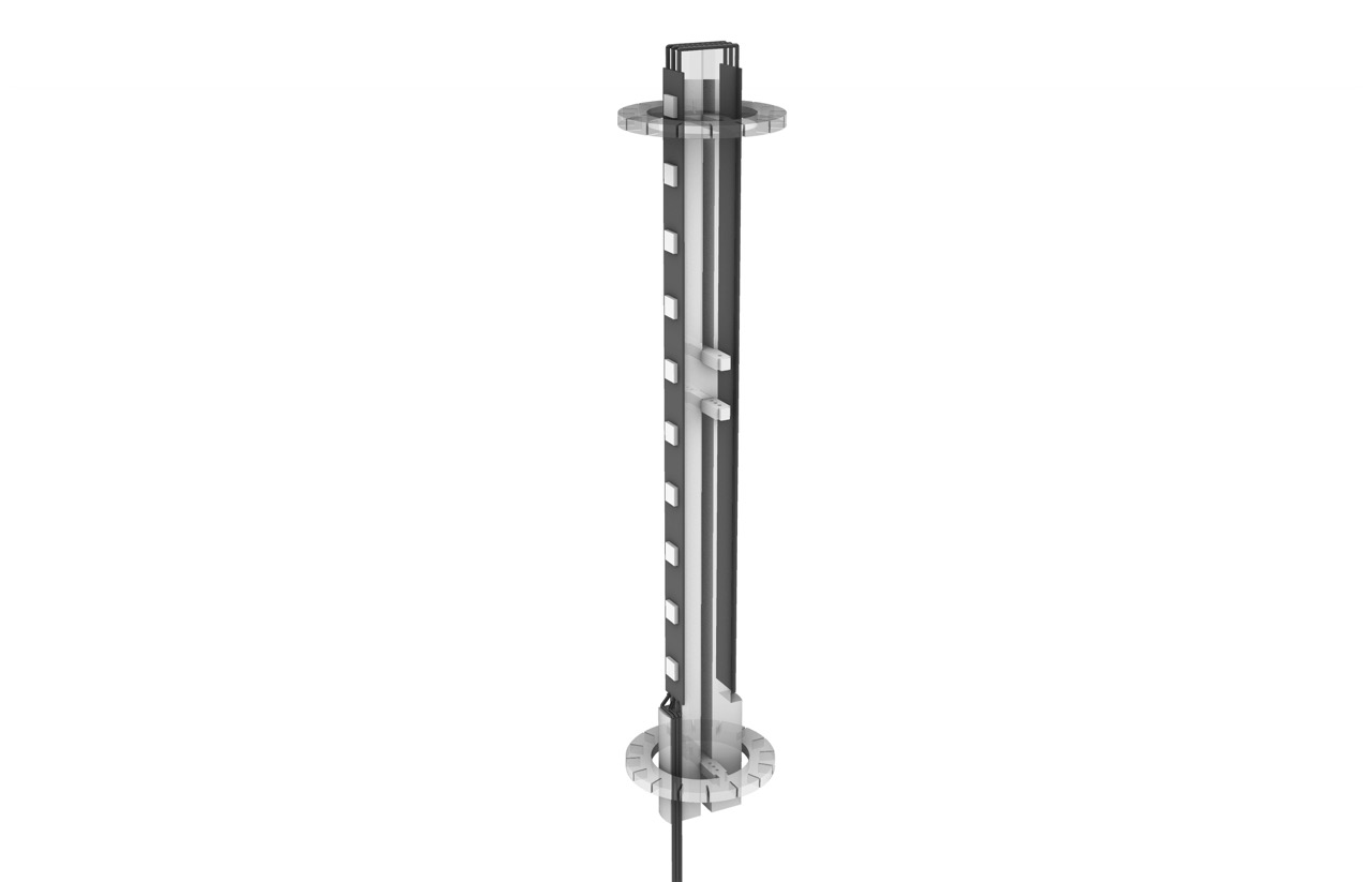
3D modelling the mechanism in Rhino
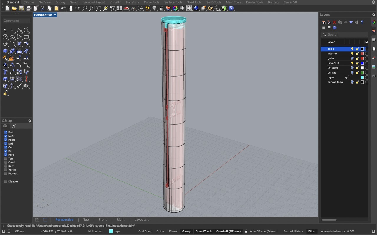
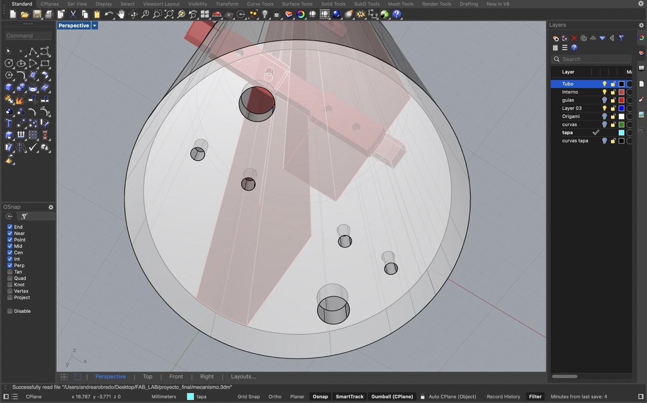
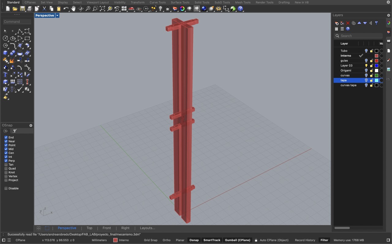
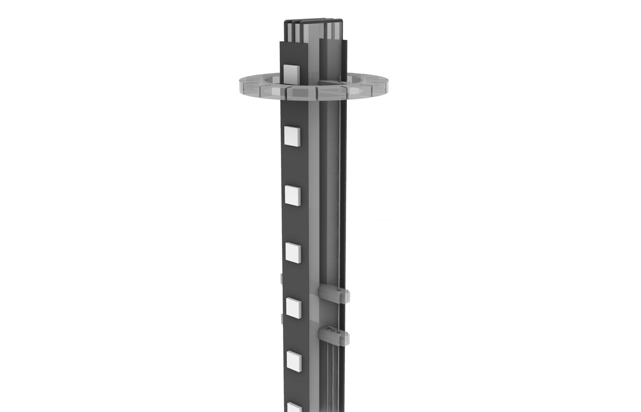
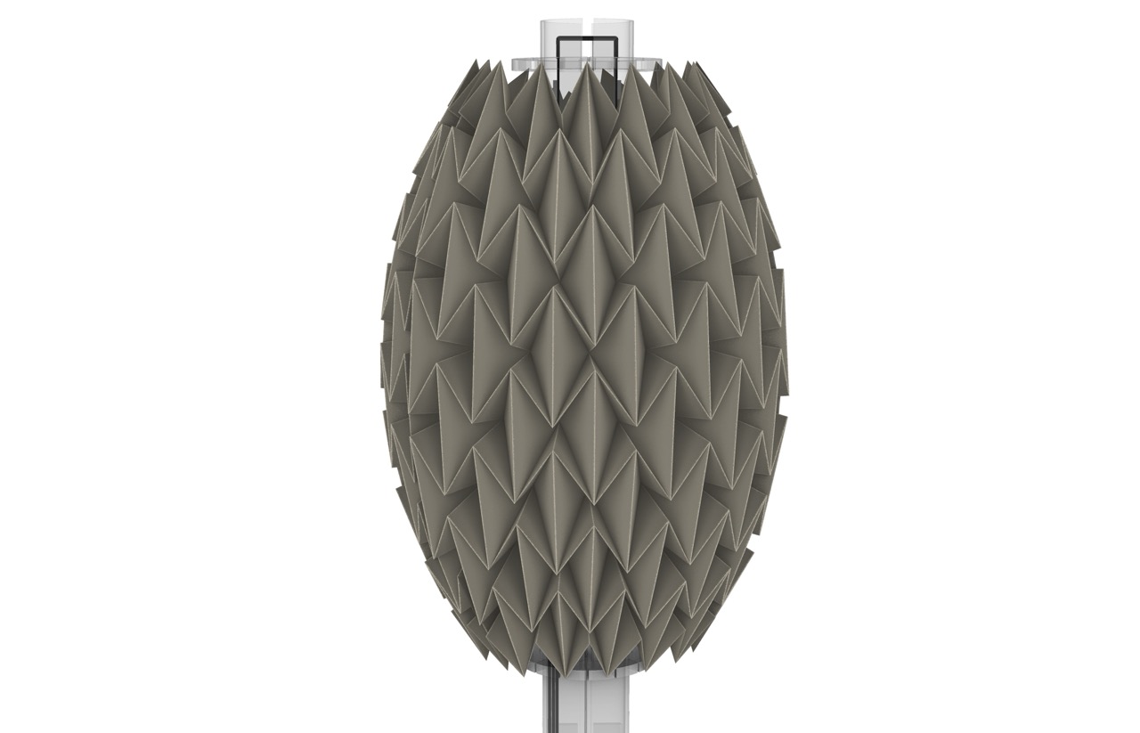
To formally establish the mechanism idea, I created a 3D model in Rhino. This helped identify both limitations and opportunities to make the mechanism more reliable. Visualizing the mechanism in 3D allowed me to see if it would actually work, I had to make some minor modifications, however the overall concept remained the same. Below is the final structure of the origami lamp, with the white cylinder representing the origami structure.
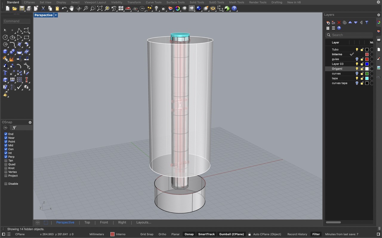
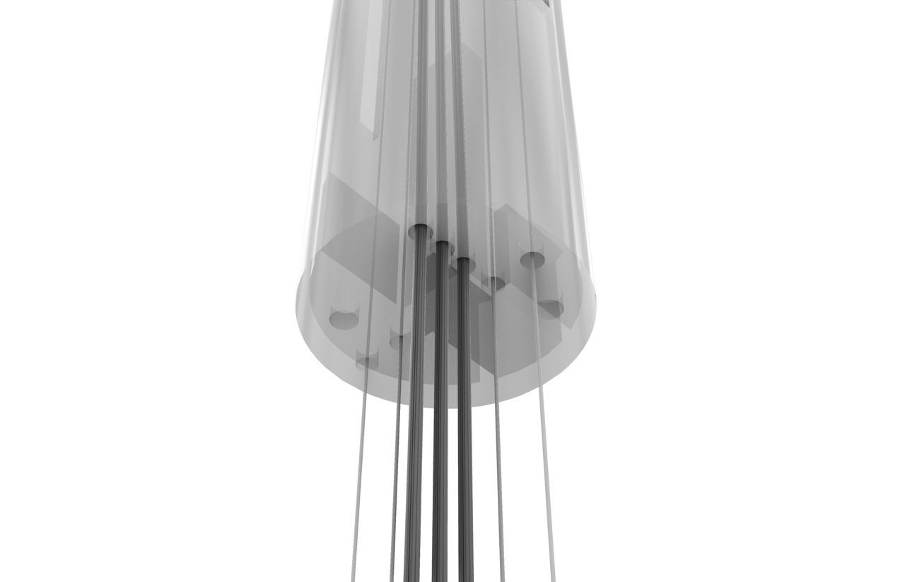
Key designed elements
The central tube features two side slots functioning as a rail system for the origami movement. It also includes four holes at the base to allow the mechanism wires to pass and connect to the motor and two additional holes for screws to secure the tube to the base.
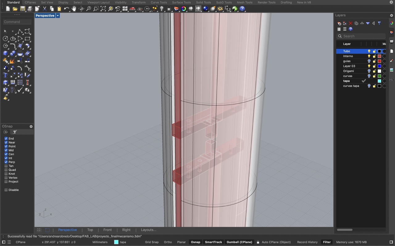
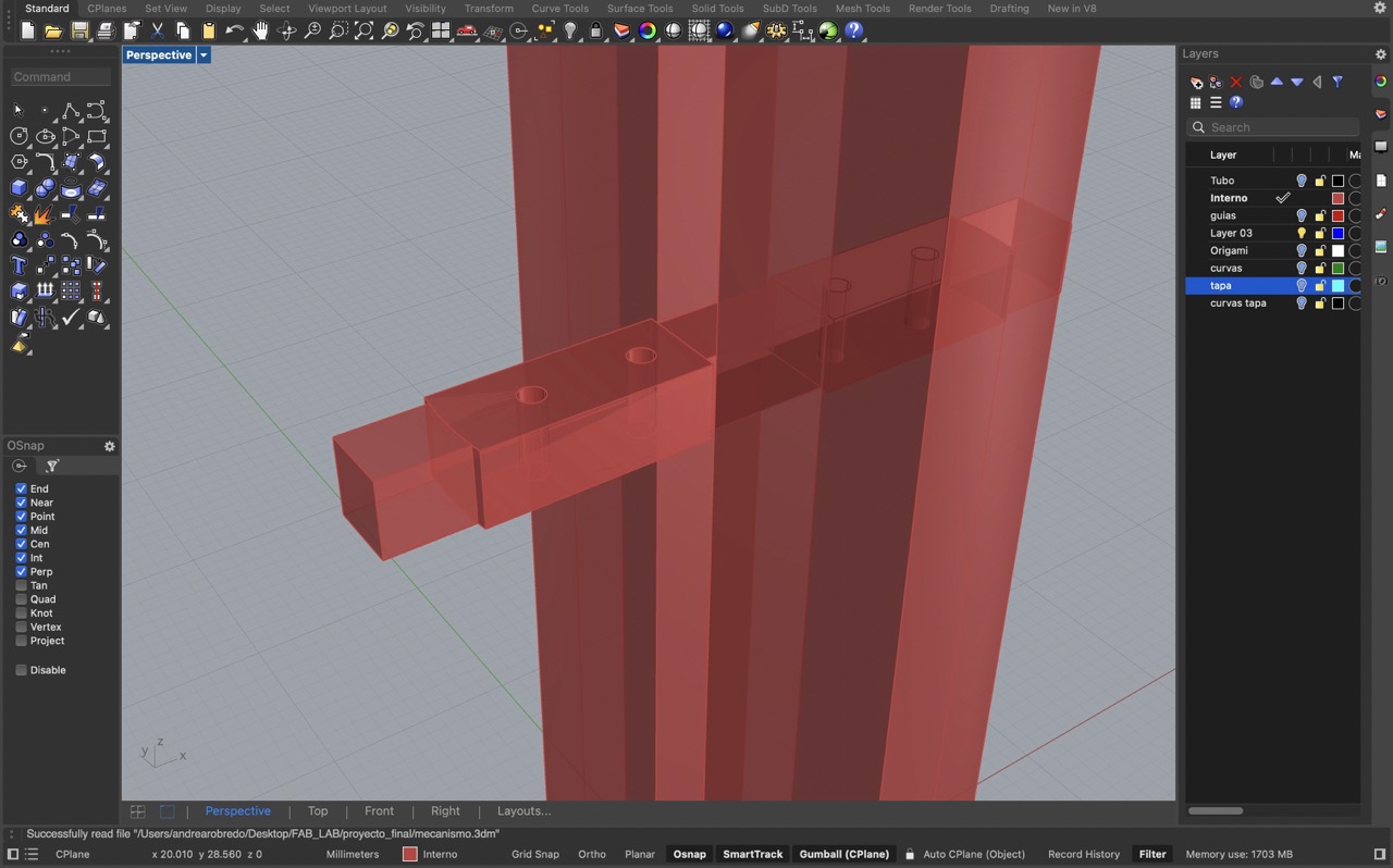
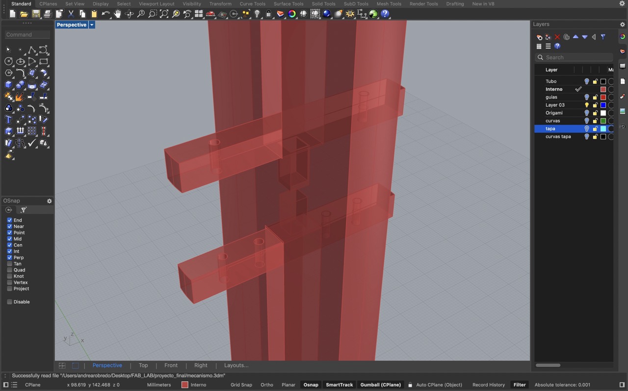
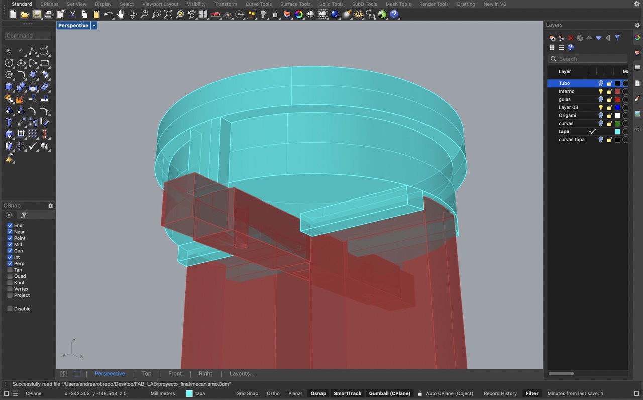
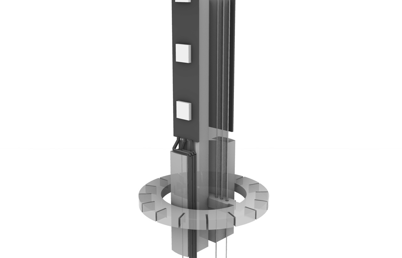
In the internal structure, the fixed central piece also has two slots to guide the internal mechanism. The pieces have a slight offset to ensure alignment with the rail and the two central fixed pieces have an extruded square to facilitate assembly with the structure.
The top lid was designed as a guide to ensure the internal structure remains in place. To do this I filled the space left in the side slots and included two rectangles to guide and keep the internal structure aligned.
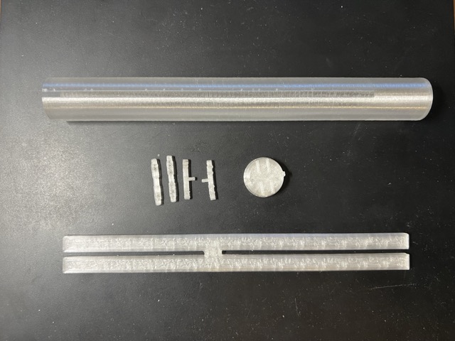
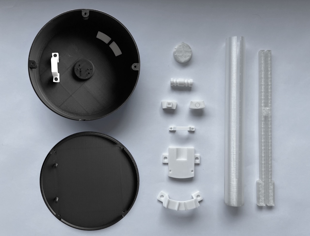
3D print mechanism
Here are the 3D-printed pieces along with their final results.
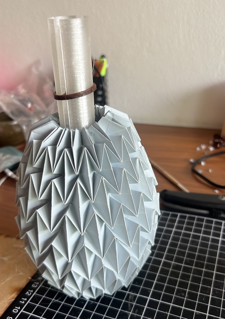
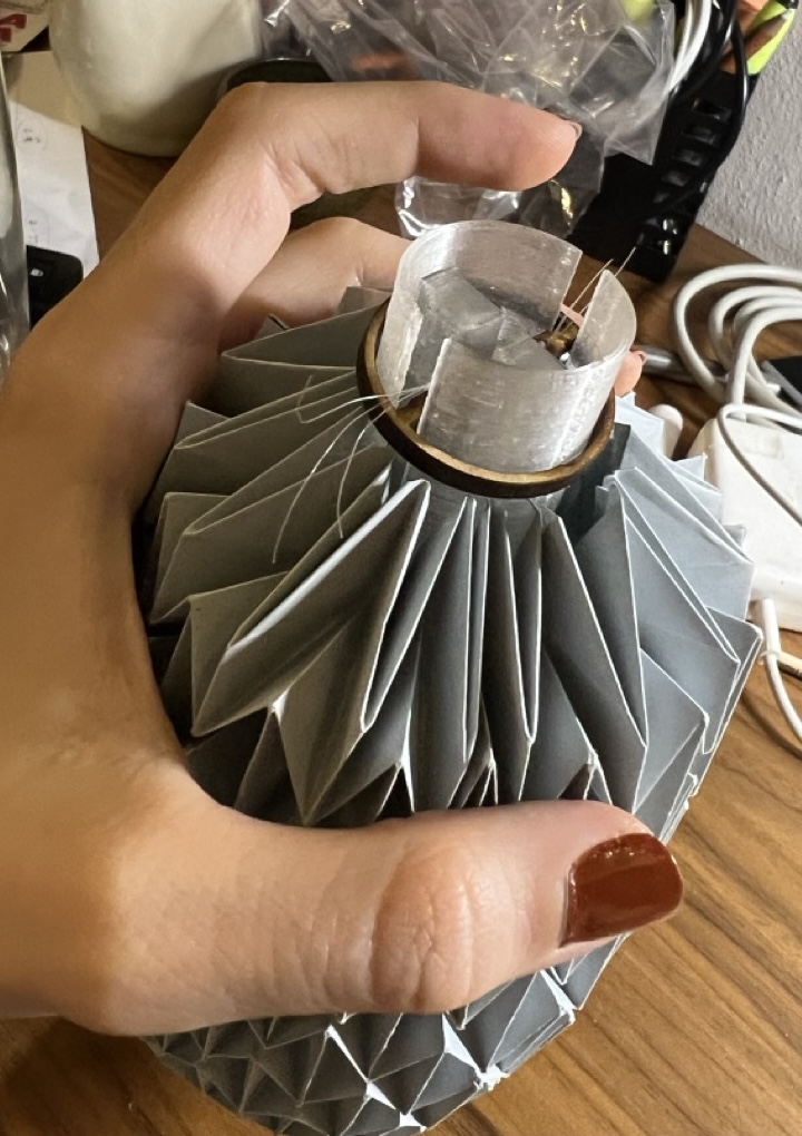
Trying mechanism
I added the wires connecting each piece, which was a challenging task due to the small size of the components and the tendency of the string to get tangled and knotted.
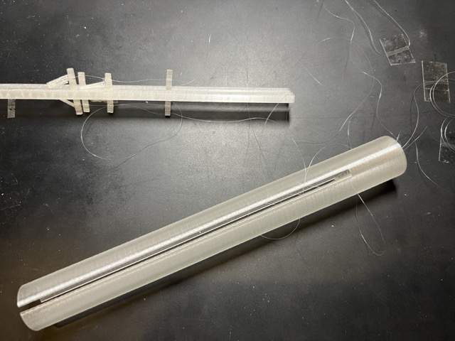
Here, you can see how the mechanism works. By pulling on the outer strings, the top section moves downward, and by pulling on the two middle strings, the bottom section moves upward.
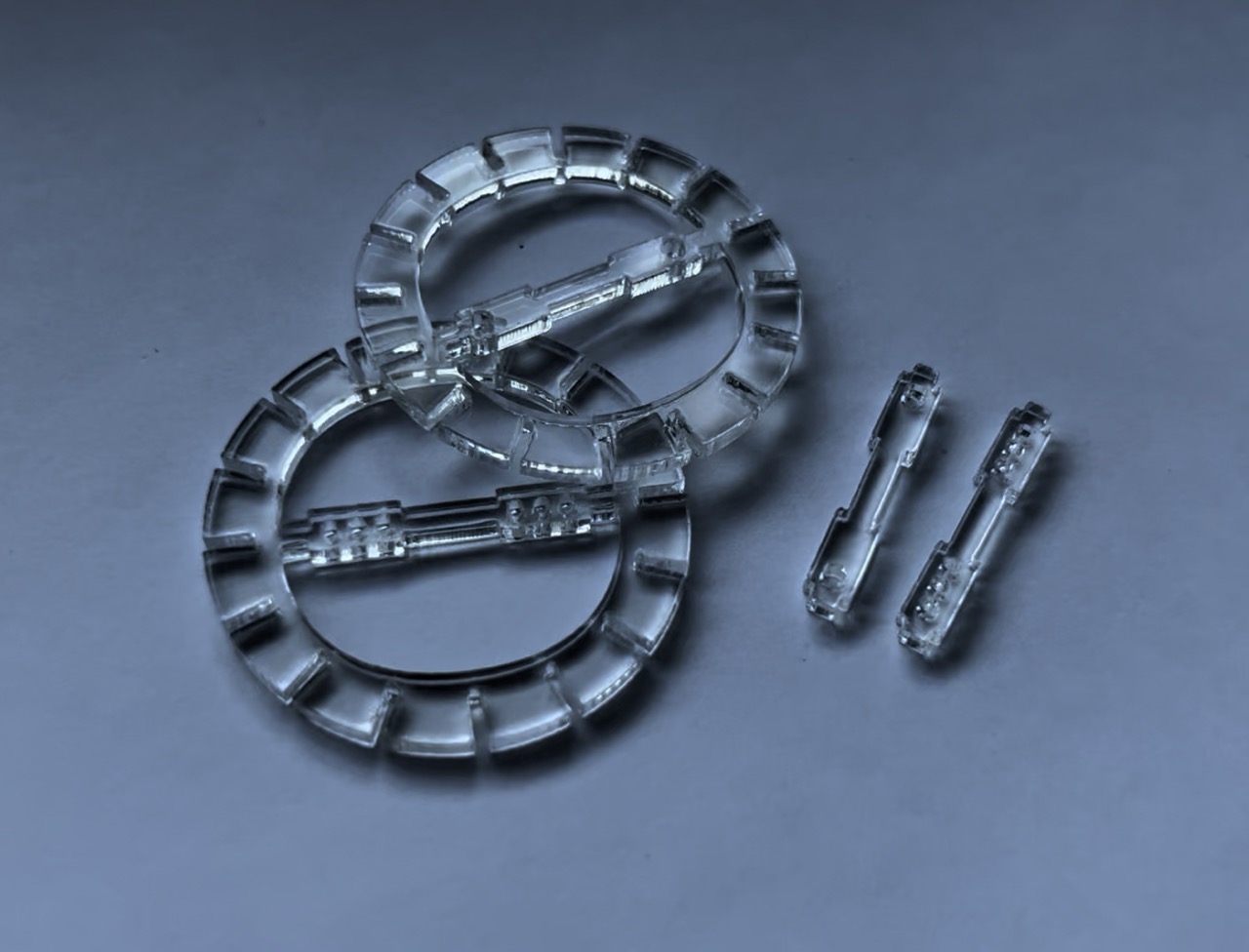
Modifying mechanism pieces
I had to redesign the pieces connected to the origami because attaching the origami structure at only two points proved to be very difficult. I decided to laser cut MDF circles with the same internal design to see if it would work better. Although it remained a challenge to attach the folds, I managed to secure the prototype using silicone. While the finish wasn't aesthetically pleasing, it was functional enough to test the mechanism and functionality of the lamp.
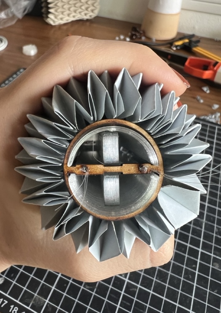
Based on this experience, I decided to modify the file and create small cuts around the perimeter, allowing each origami fold to be more easily and securely attached to the structure. I also decided to use acrilic intead of mdf given that this material goes better with the design.
Necessary elements
After making these prototypes, I was able to identify the necessary elements, materials, and processes required for my final project.
Element |
Material |
Process |
|---|---|---|
| Origami structure | 118 g paper | Laser engraving |
| Base | Black PLA | 3D printing |
| Buttons | White PLA | 3D printing |
| Tube mechanism | Transparent PLA | 3D printing |
| Internal Mechanism | 3 mm acrilic | Laser cut |
Components needed
I decided to determine which electronic components I would need and analyze the pinout of each one before designing the PCB.
- 1 DC motor - 6V
- 1 motor driver
- 1 on/off button
- 1 breathing exercise button
- Neopixel led strip
- 5V regulator
- External power source
What is left to do
Project development
After all the prototyping work, it's time to start making the final lamp, incorporating the observations and necessary modifications from the prototype. To complete this project, I will need to follow these steps:
- Design the PCB board, considering the internal accommodation of each component.
- Check with my instructors to ensure everything looks correct.
- Create the files for cutting the board.
- Cut the board using the milling machine.
- Solder the components.
- Begin making some test codes to see how the neopixel strip and the DC motor work.
- Develop the final code.
- Figure out how to keep each component in place.
- 3D print the base, buttons, and internal structure.
- Assemble the mechanism.
- Test the lamp.
I am very proud of the project so far. It has been a learning experience with some frustrating moments, but I am very excited to see how it turns out. I just need to organize my time and execute the final tasks.
PCB design
KiCad
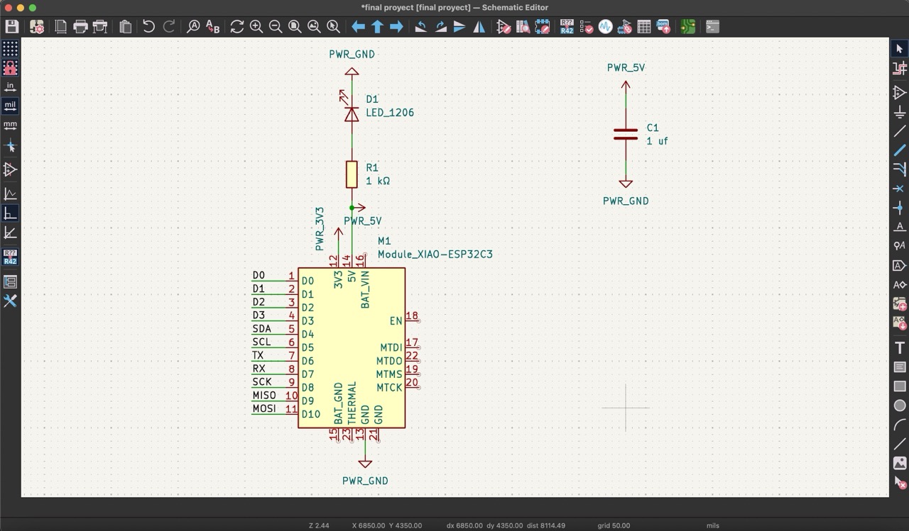
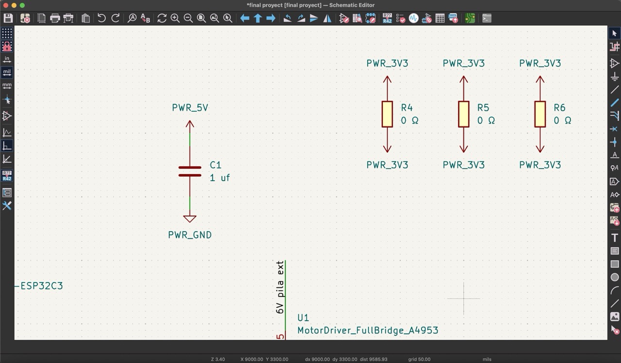
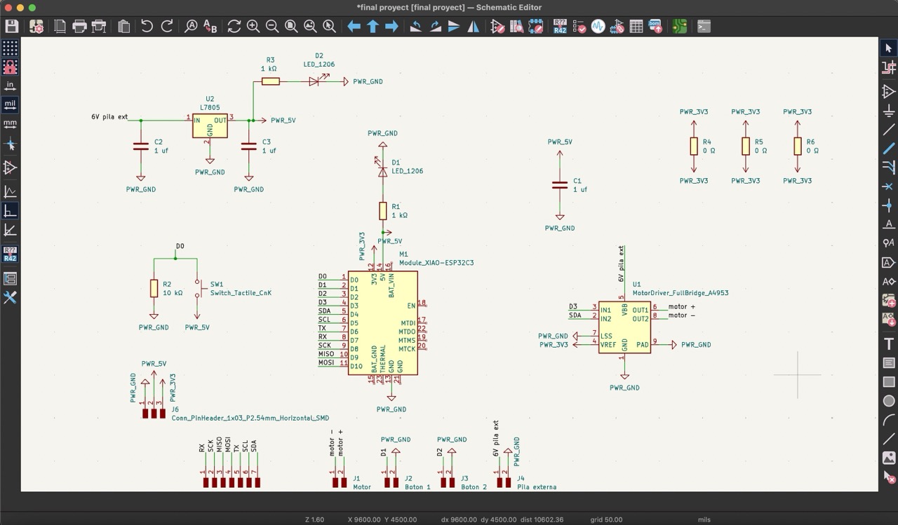
To start, I added the ESP32-C3 microcontroller from the 'Add symbol library' in KiCad and labeled each pin accordingly. I also included a LED with a 1 kΩ resistor connected to the 5V pin to verify if it is receiving power once connected. I also added a capacitor.
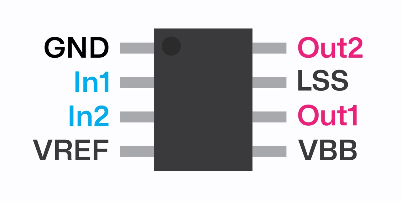
Next, following the pinout of the A4953 motor driver, I labeled the corresponding pins. I also added a button connected to D0 with a 10 kΩ resistor.
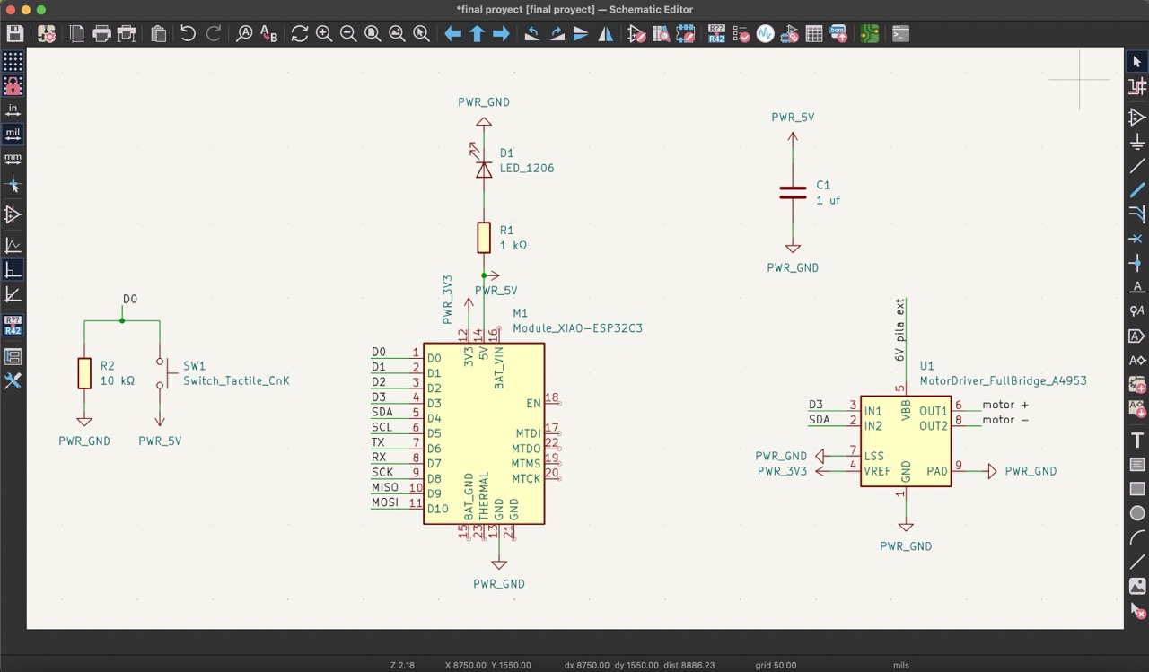
To power the microcontroller with the same external battery source, I included a 5V regulator (78M05), which connects to the external power source on one end and to the 5V pin on the other.
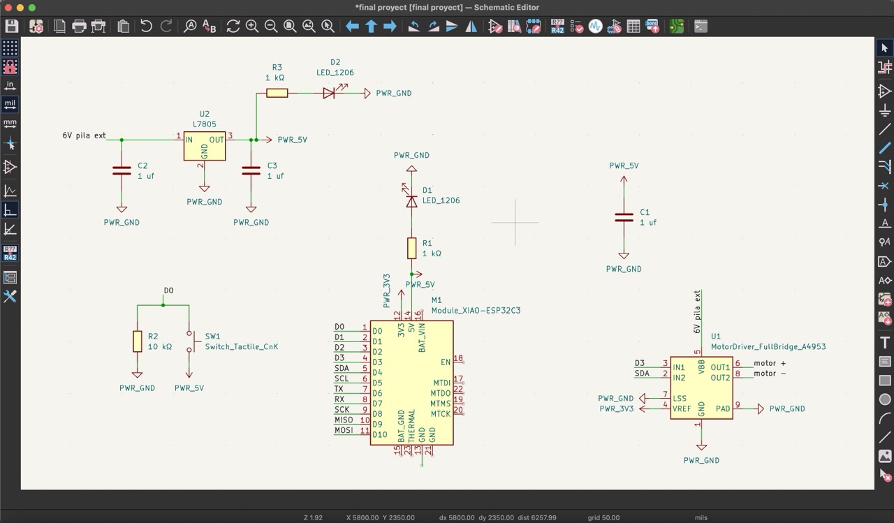
Then, I added pins for each of the components I will be using. This includes two pins for the motor, two pins for button 1, two pins for button 2, and two pins for the external battery source. Additionally, I provided 3 pins for ground, 5V, and 3V, and 7 pins for the remaining connections.
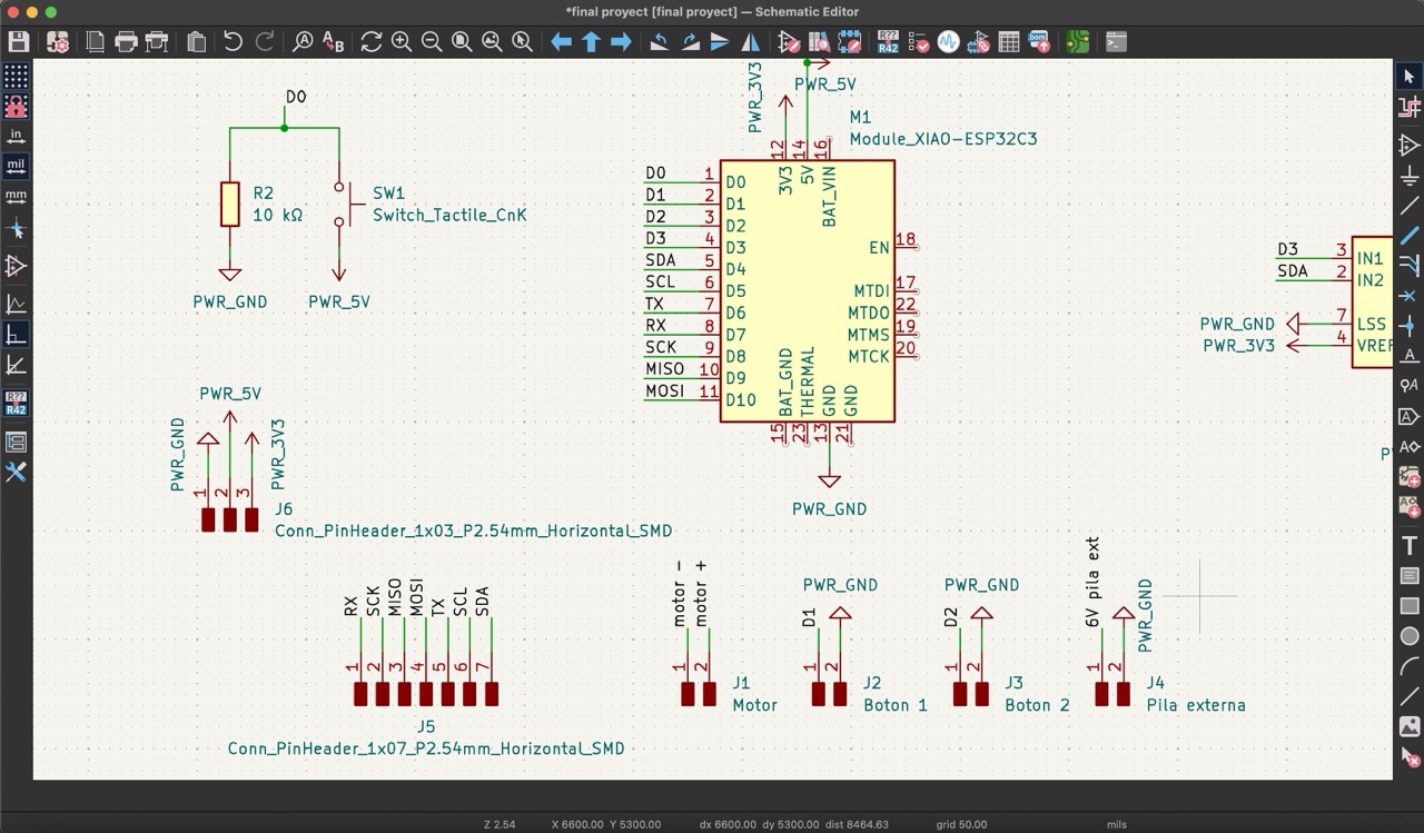
Finally, while designing the PCB, I realized I needed three bridges to correctly connect the 3V line.
This is the final schematic for my PCB board.
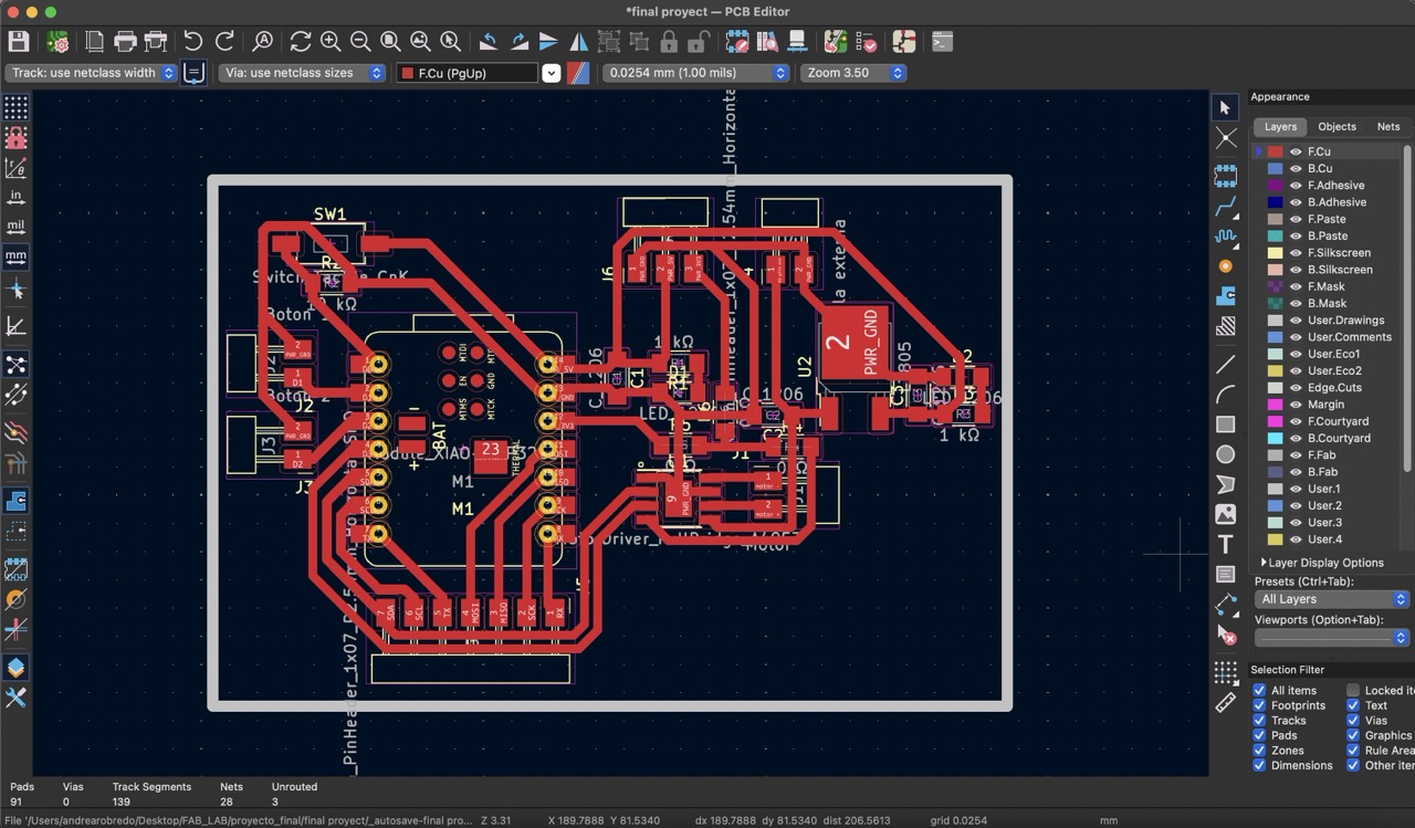
Then, moving on to the PCB editor, I found it quite challenging to organize each component and make the necessary connections. I aimed to strategically place the pins so that when connecting them to the physical components, they would be conveniently positioned. This approach was intended to ensure a more organized assembly for my lamp.
**For more detailed guide on using KiCad, you can refer to my documentation from week 8.
Cutting PCB board
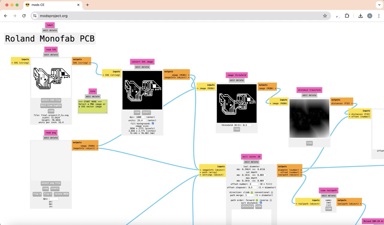
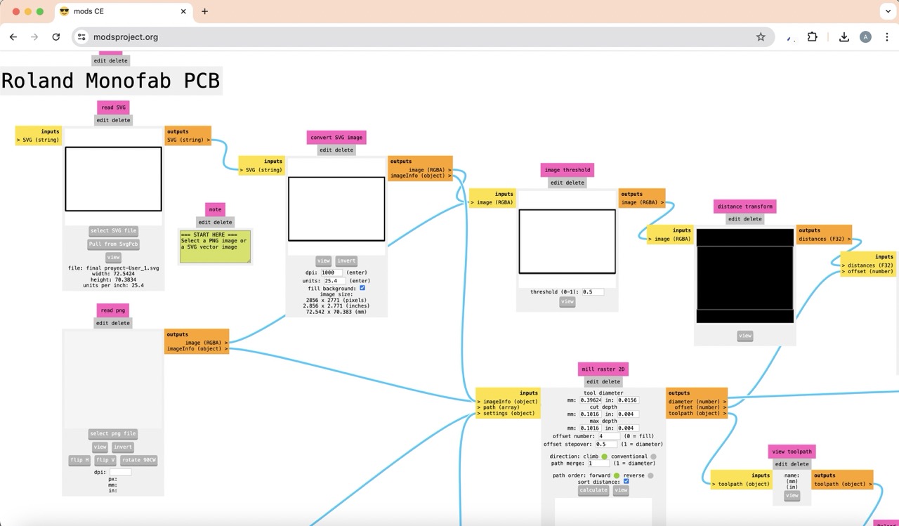
I created the files to cut the traces and outline of the PCB using the 'mods' platform.
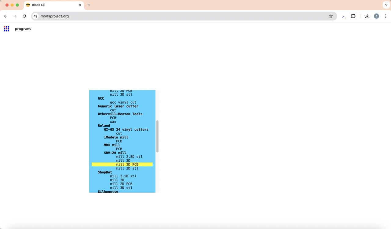
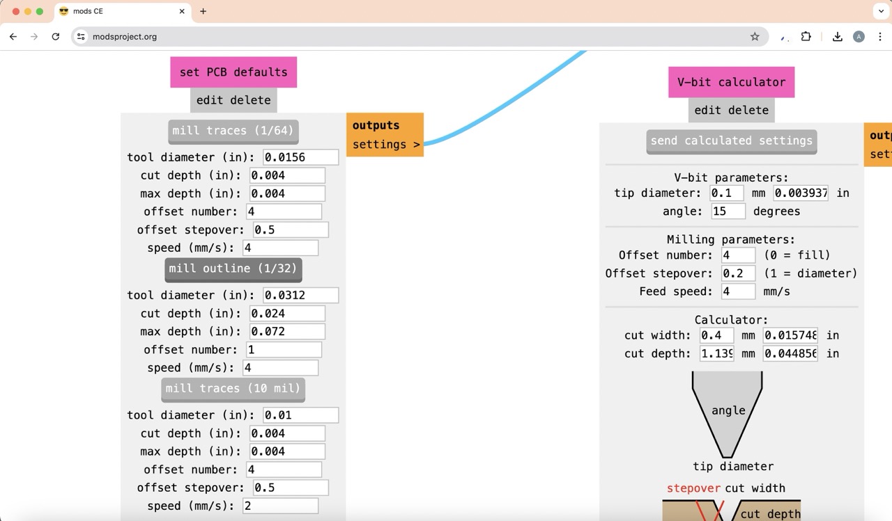
For the traces, I uploaded the .svg file, made sure to invert it (since black represents the cutting area), and clicked on 'mill traces'. I then set the origin to 0, 0, 0.
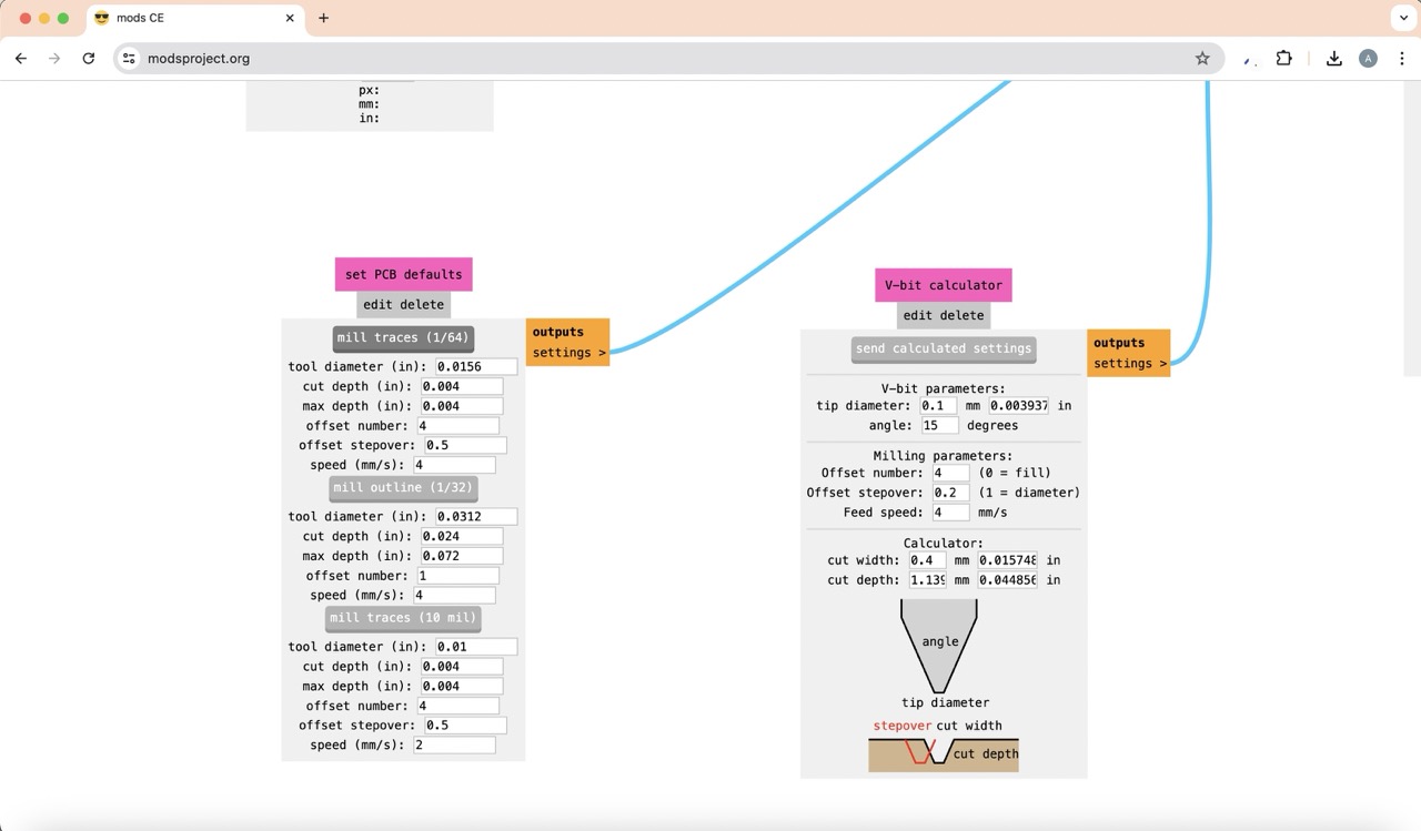
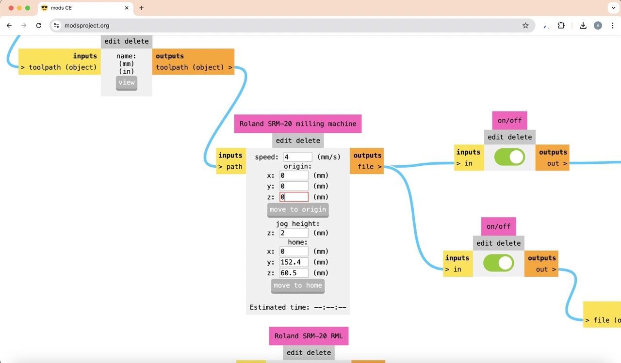
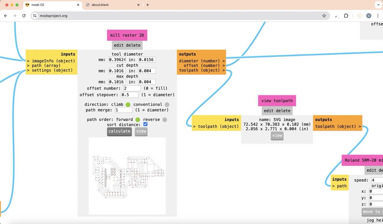
Next, I made the file to cut the outline by uploading the corresponding .svg file, clicking on 'mill outline', setting the origin to 0, 0, 0, and finally changing the tool diameter to 1mm.
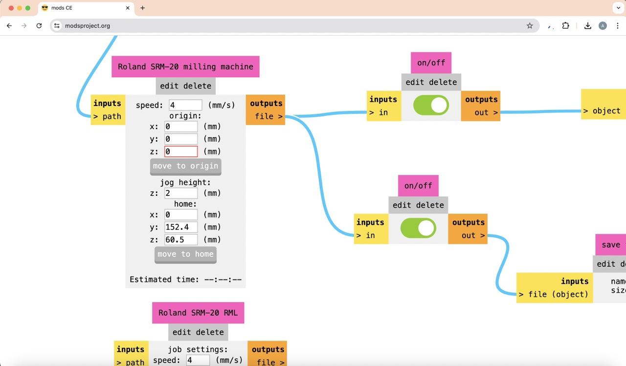
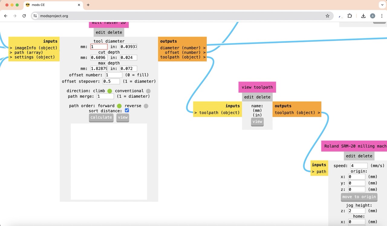
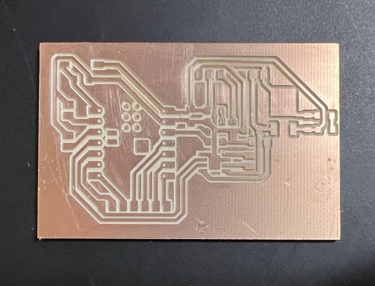
Then, I uploaded the files to the Vpanel software to cut my PCB and this was the final result.
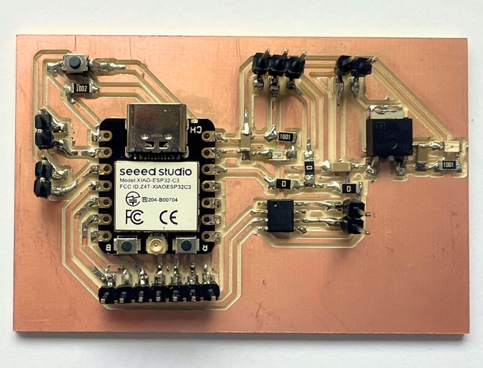
Soldering
Finally, I soldered each component. I believe my soldering skills have improved significantly with all the practice I've had.
Components used
Here you will find all of the components needed to create a breathable origami lamp, as well as prices and possible buying sites.
Component |
Quantity |
Cost |
Where to buy |
|---|---|---|---|
| Xiao ESP32-C3 | 1 | $10.5 USD | Xiao ESP32-C3 |
| Power converter | 1 | $10.85 USD | Power converter |
| DC motor | 1 | $8 USD | DC motor |
| A4953 motor driver | 1 | $2 USD | A4953 |
| Neopixel led strip | 32 cm / 20 Neopixels | $26 USD for 5m | Neopixel led strip |
| Fishing line 0.35mm | 4 m | $3.5 USD for 250m | Fishing line |
| 5V regulator (78M05) | 1 | $5 USD for 10 pzs | 5V regulator |
| Push button SMD (1206) | 1 | $0.1 USD | Push button SMD |
| Push button | 2 | $6 USD for 20 pzs | Push button |
| Capacitors 1uf (1206) | 3 | $2.5 USD for 100 pzs | 1 uf capacitors |
| 10 kΩ resistor (1206) | 1 | $2.5 USD for 100 pzs | 10 kΩ resistor |
| 1 kΩ resistor (1206) | 2 | $2.5 USD for 100 pzs | 1 kΩ resistor |
| 0 Ω resistor (1206) | 3 | $2.5 USD for 100 pzs | 0 Ω resistor |
| LED (1206) | 2 | $4 USD for 100 pzs | LED |
| Male pin header | 18 | $5.5 USD | Male pin header |
Assembly
System integration
Laser engraving origami pattern
3D printing elements
Laser cutting mechanism pieces
PCB design
Assembling process
To start, I attached the middle laser-cut pieces to the 3D printed inner structure.
Next, I pasted the neopixel strip to the 3D printed inner structure, connecting and soldering the wires of both strips.
I then took the outer 3D printed tube structure, threaded the wires from the neopixel LED strip through it, and passed four fishing string cables through their corresponding holes. These strings were integrated into the mechanism. For a clearer understanding of the mechanism, refer to the sketches in the mechanism section of the documentation.
Following this, I adhered the origami structure to each of the cuts in the mechanism ring.
I then passed the four mechanism cables and the three neopixel cables through the base of the lamp, pasting the mechanism cables around a 3D printed cylinder with designated space for each one.
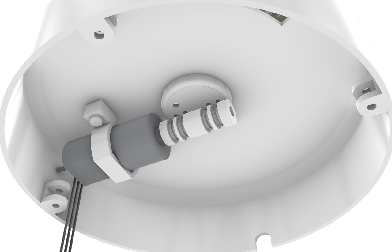
Next, I secured the motor to the base using a 3D printed piece designed to hold it in place.
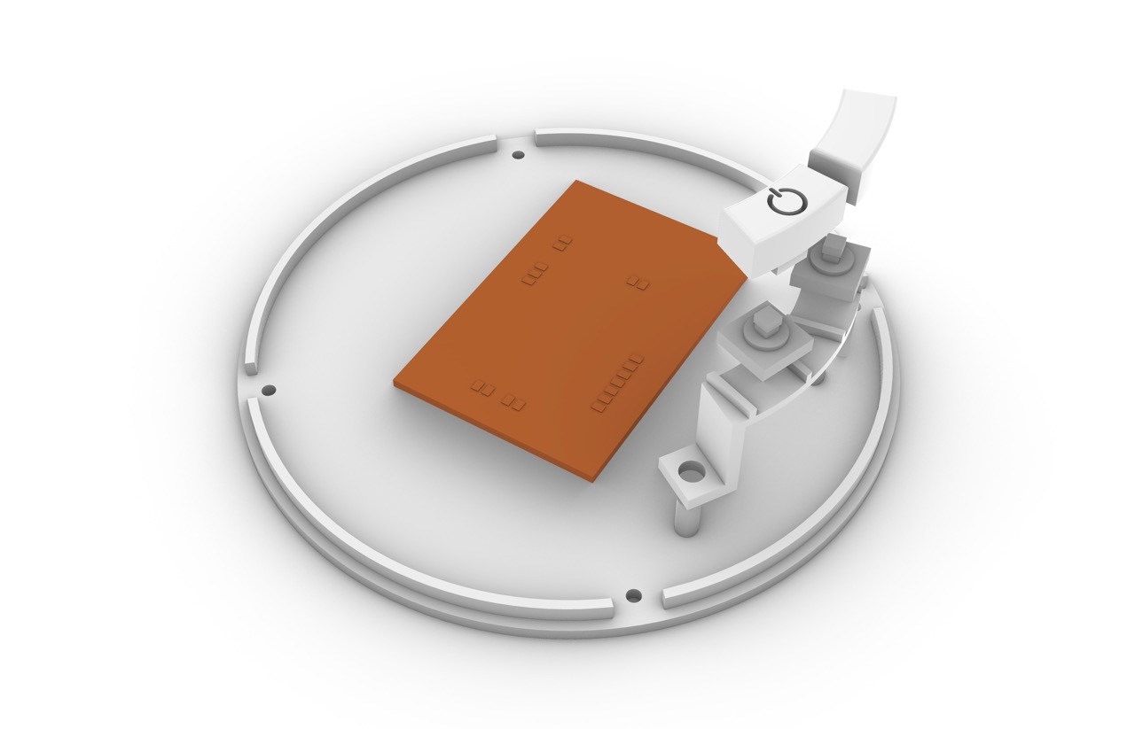
I then assembled the buttons, attached my PCB to the base, and connected each component according to the schematic in the programming section.
Finally, I closed the base and secured it with screws.
Programming
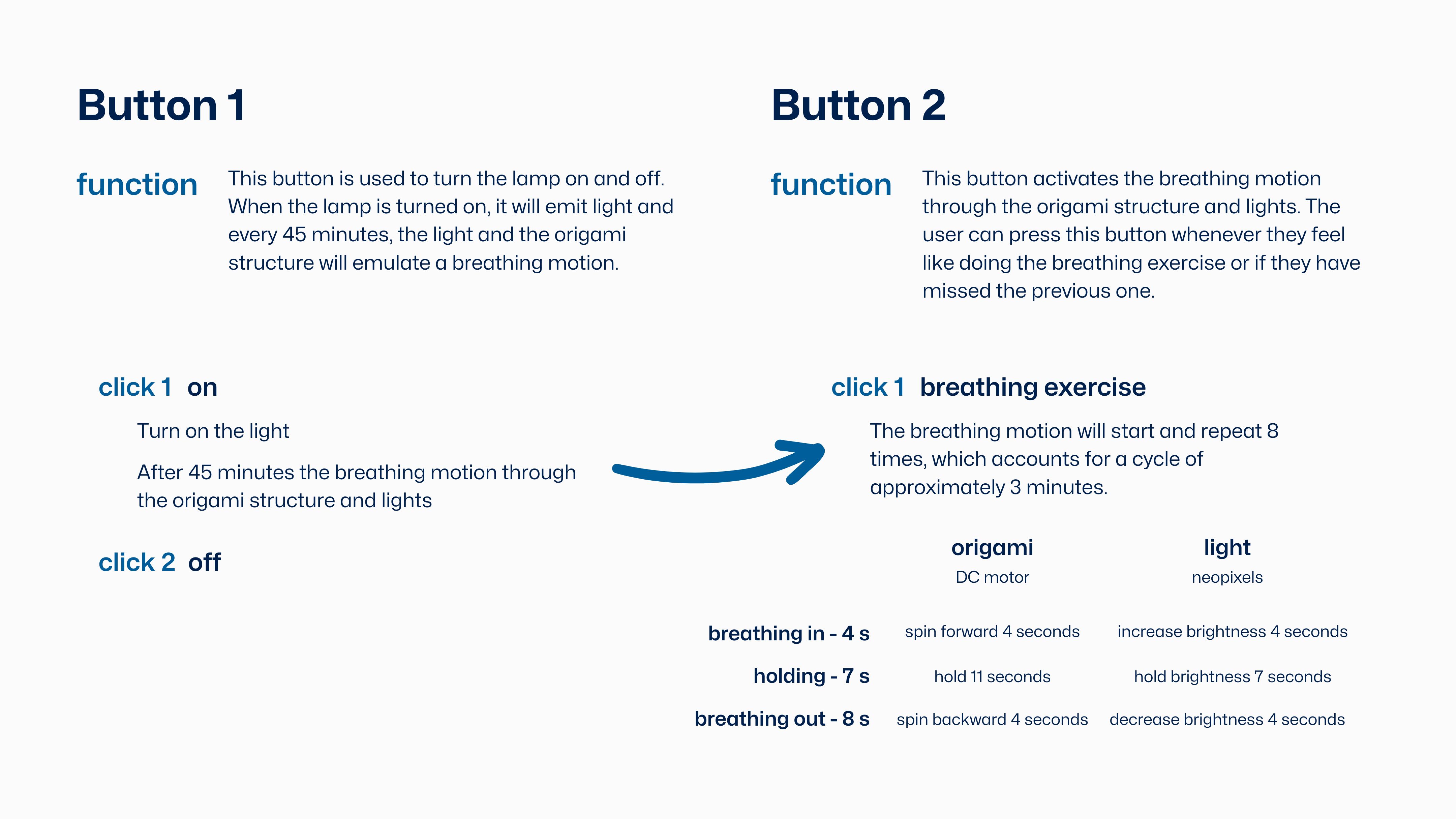
Before starting to program, I decided to create a flow diagram to outline the functions of each button and understand what needs to be done for the code to work fully.
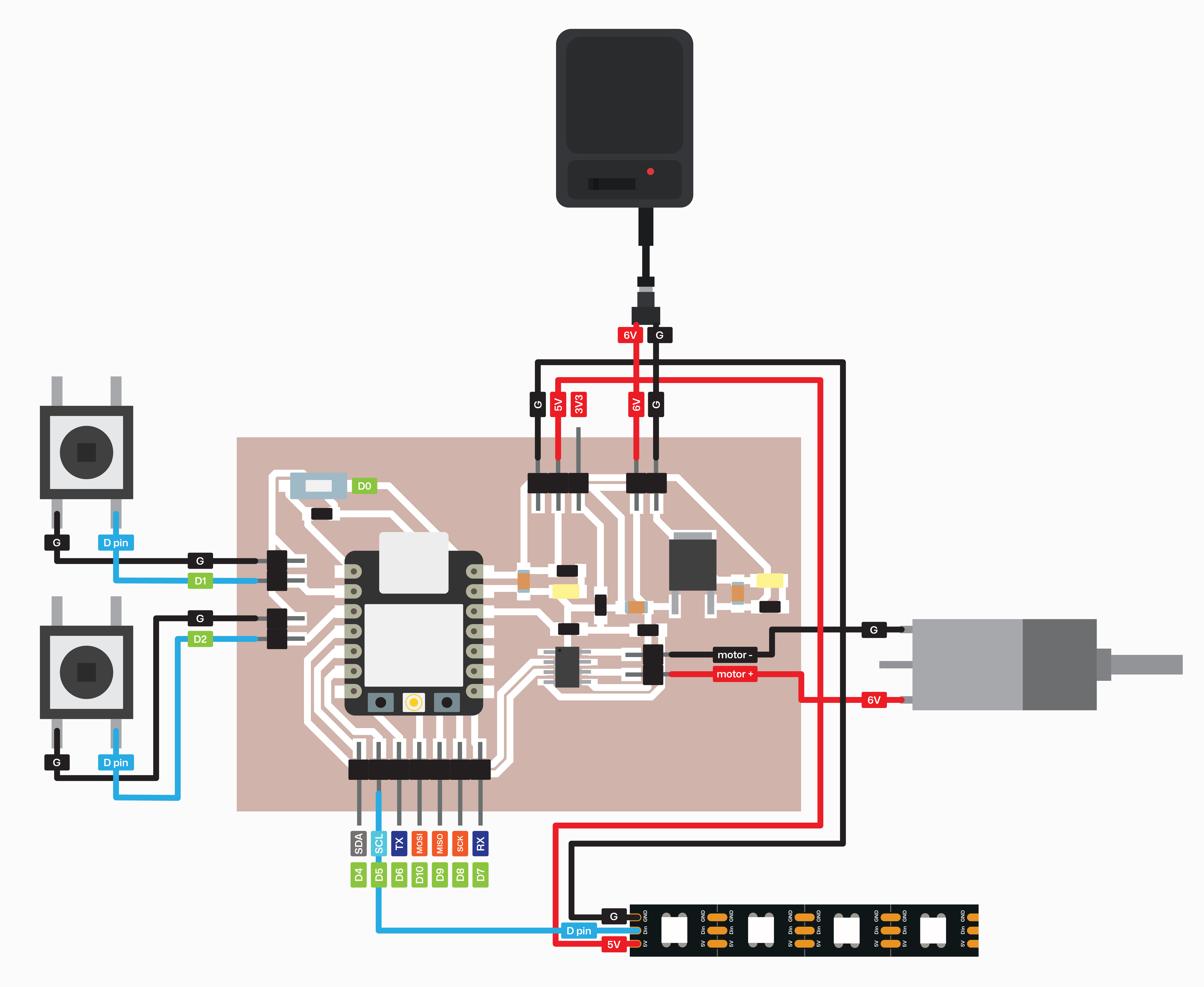
Schematic
I created a visual diagram to represent all the connections needed between the components and the PCB.
Let's start!
To begin, I decided to use C++ programming with Arduino. I started by programming the Neopixel LED strip and then moved on to the DC motor to test their functionalities separately. Once I confirmed that both components were working correctly, I integrated them into a single program.
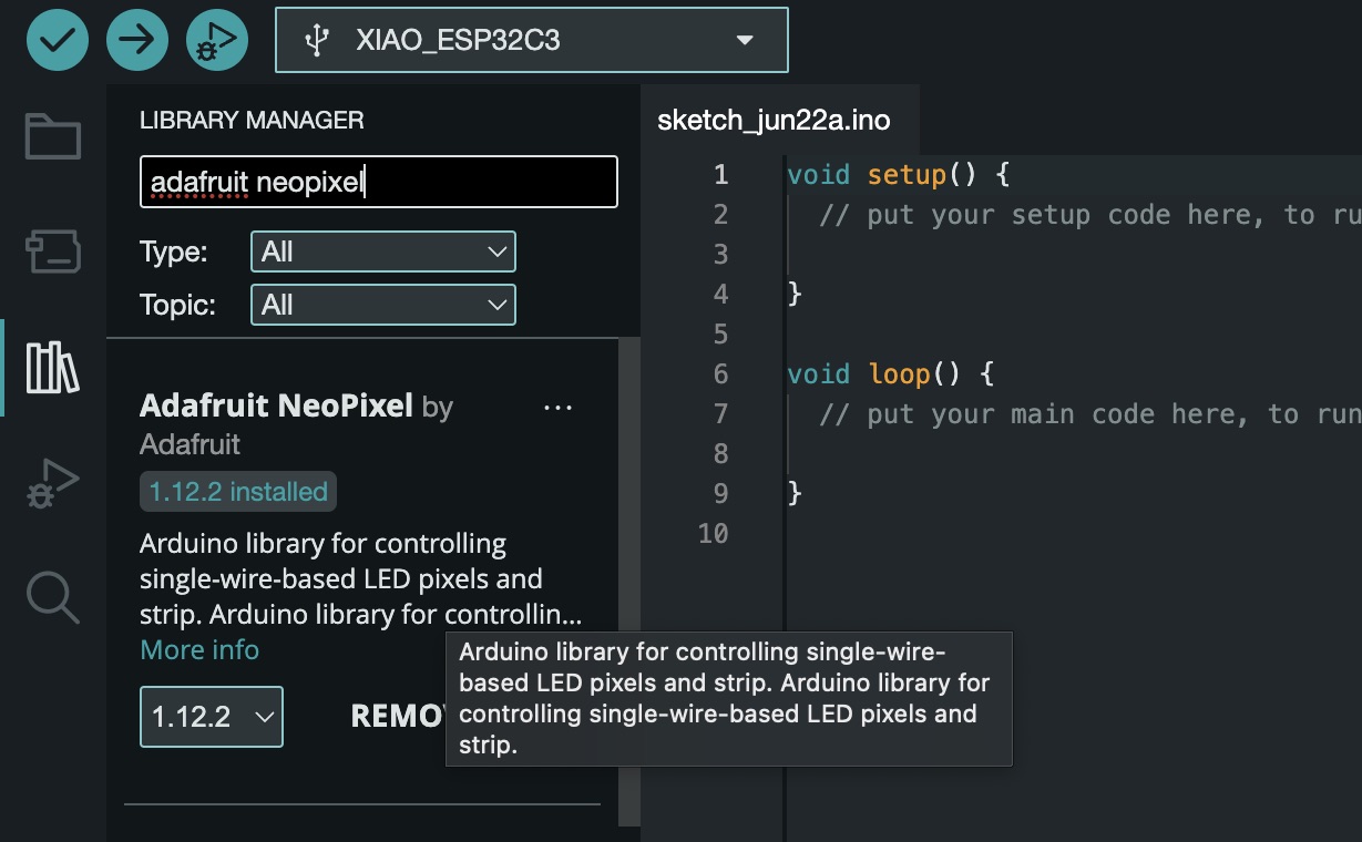
Neopixel led strip
For the Neopixel strip, it was necessary to first install the 'Adafruit NeoPixel' library.
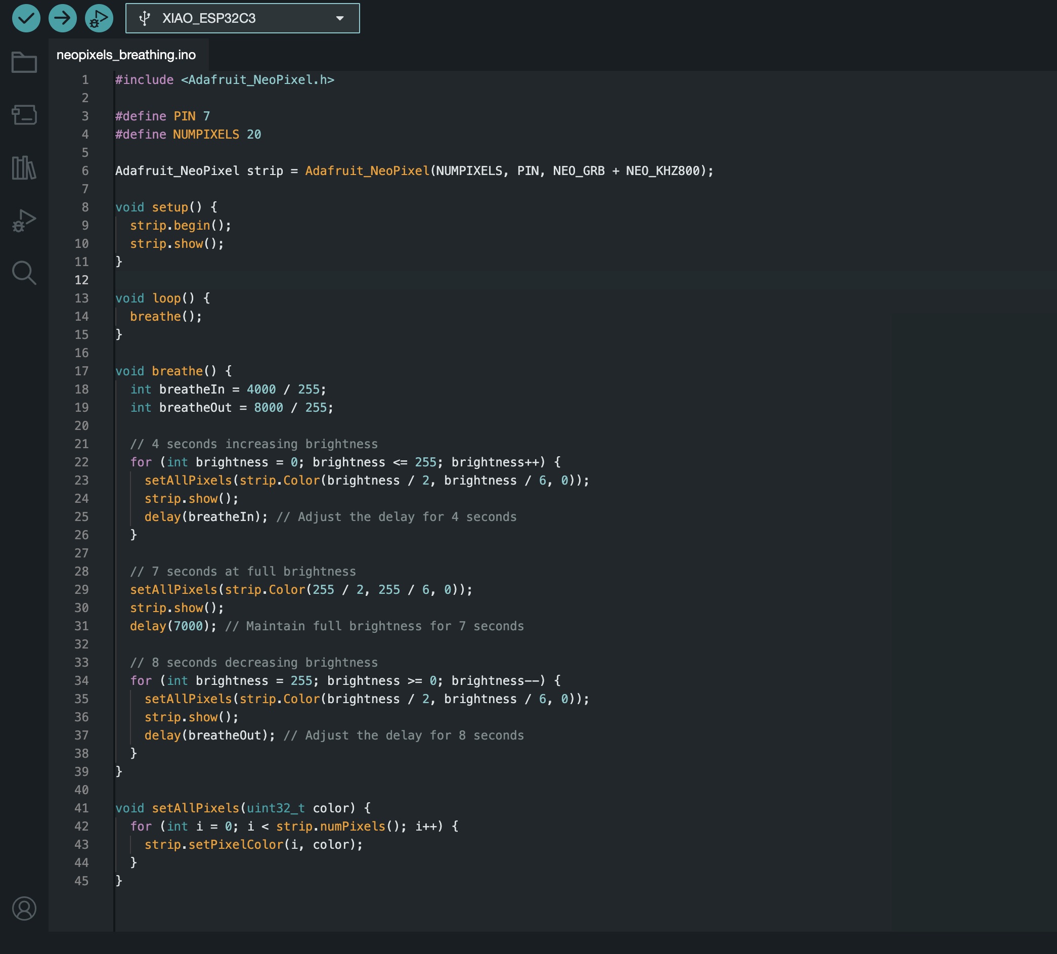
Here is the code I used. I began by defining the pin where the Neopixels were connected and specifying the number of Neopixels on the strip. In the setup phase, the LED strip is initialized, and all LEDs start in the off state. The breathe function consists of three stages: increasing brightness over 4 seconds by incrementing the brightness value, maintaining full brightness for 7 seconds, and then decreasing brightness over 8 seconds by decrementing the brightness value. The setAllPixels function sets all LEDs to a specified color, in this case, a warm color, to facilitate smooth brightness transitions in the breathe function.
Here is a demonstration of the breathing effect on the Neopixel LED strip and the origami structure.
DC motor
Moving on to programming the motor, I encountered several issues. Initially, when I connected the motor to a 6V external battery, it didn't move. Using a multimeter, I discovered that even though I was using four 1.5V batteries, the motor wasn't receiving the full 6V. I consulted Oliver, one of our instructors, who suggested using a 9V battery, assuring me that the motor could handle it.
Here, you can see that the 6V battery is insufficient to power the DC motor effectively.
I continued programming with the 9V battery, but encountered another problem. When I attempted to reduce the motor's speed using PWM, the motor would start to fail and emit a static noise. After consulting with several people, I learned that 9V batteries are not ideal for controlling motors due to their inconsistent power output.
Using the 9V battery worked, but when the speed was lowered to 80, the motor would stop working altogether. Even at a speed setting of 120, the motor's spinning was inconsistent.
Ultimately, I decided to use a 6V power converter that plugs into the wall. This solution provides a stable voltage, ensuring the motor operates correctly without the issues caused by battery power.
With the external power converter, the motor operated perfectly, maintaining consistent performance even when the speed was reduced. This demonstrates the importance of a stable power source for reliable motor operation.
Final code
Now it is time to join both codes and add the function of each button.
While combining the codes for the motor and LED strip, I conducted several tests to ensure the motor speed and the breathing effect for the LEDs were functioning correctly.
During these tests, I noticed that if the motor rotated more than the length of the string allowed, it would cause the string to roll back when released, creating an unintended double breathing effect. To address this, I set the motor speed to 50 and limited the inhaling and exhaling duration to 4 seconds, even though the light effect during the exhaling action lasts the intended full 8 seconds. This adjustment ensures the motor and LED strip work in harmony, providing a smooth and consistent breathing effect.
For the final code, I began by initializing the LED strip with 20 pixels connected to pin 7, setting up motor control on pins 5 and 6, and defining two button inputs on pins D1 and D2. In the `setup` function, serial communication is started, the LED strip is initialized and turned off, the motor pins are set as outputs and initially turned off, and the button pins are set as inputs with pull-up resistors.

The main loop continuously checks the states of the two buttons. If `button1` is pressed, the LED strip is turned on at full brightness using the `turnOnFullBrightness` function. If `button2` is pressed, a sequence of actions is executed eight times, managed by the `executeSequence` function. This sequence involves three main actions: moving the motor forward while gradually increasing LED brightness over 4 seconds.

Stopping the motor and maintaining full LED brightness for 7 seconds, and reversing the motor while dimming the LEDs over a total of 8 seconds. The motor stops after the first 4 seconds of dimming, while the LEDs continue to dim for the remaining 4 seconds. Finally, the `setAllPixels` function is used throughout the code to set all LEDs to a specific color, ensuring synchronized updates across the strip.