4. electronics production
This is a very exciting week for me, I am eager to learn how to create a PCB board, using the milling machine, and experiment with soldering different components. To start, we had a class where we learned about the milling machine and the process of creating PCB boards as well as the types of boards used, and the materials they're crafted from. We also learned important details like minimum clearance and width tolerance for the traces, which you can find on our group assignment page. Then, I had a guided session on how to use the milling machine with Alberto Blanco, one of our instructors.
How to create a microcontroller board
How to mill traces:
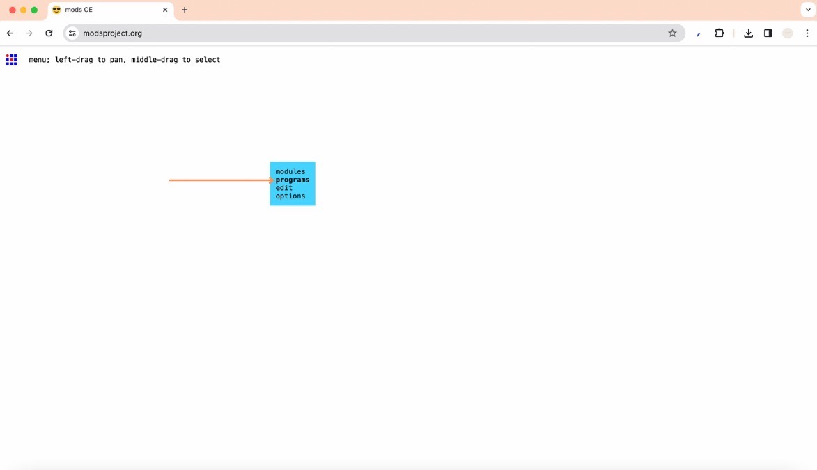
- To make your milling file go to mods project, right click and select ‘Programs’
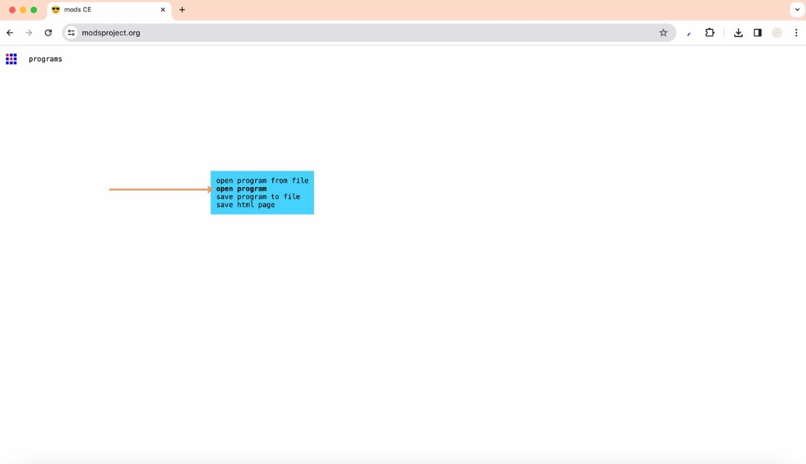
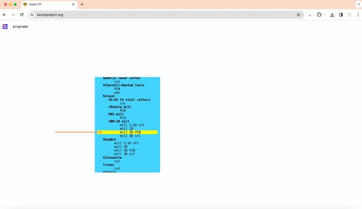
- Then, select ‘open program’ and look for your machine, in my case ‘mill 2D PCB’
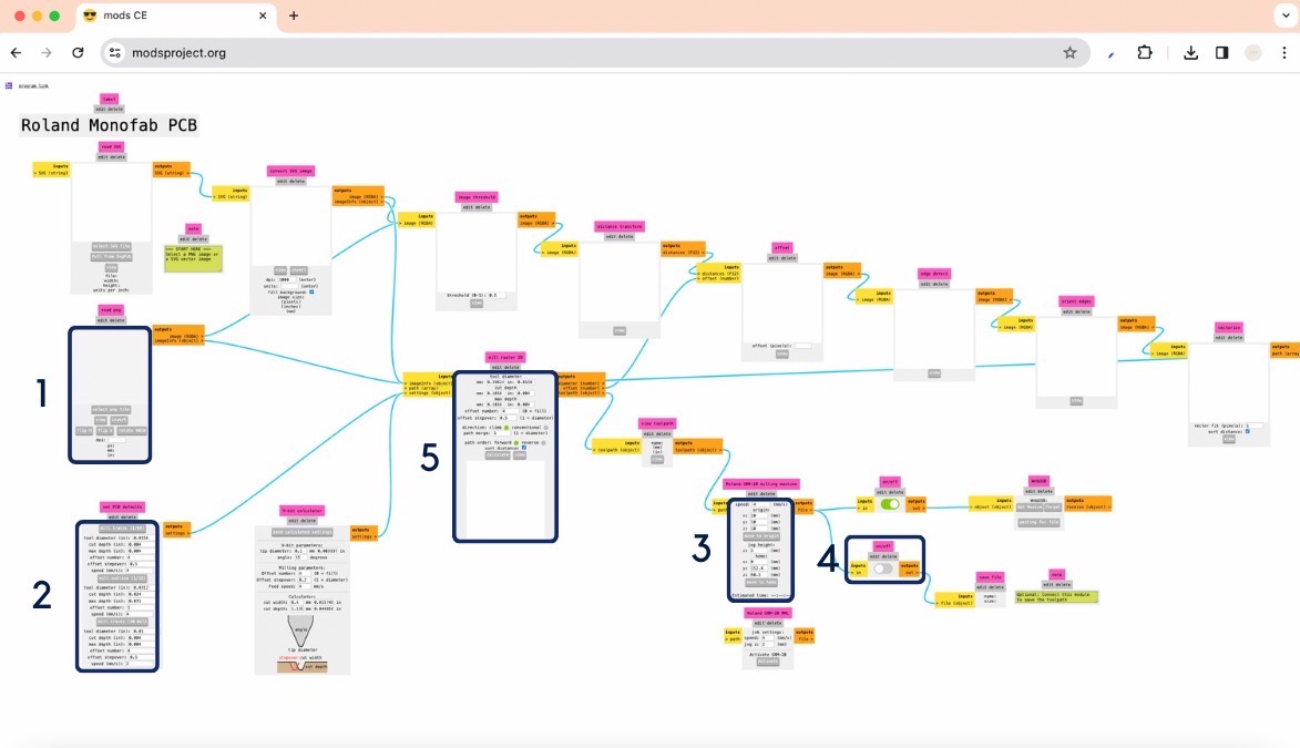
- It will open up a screen with a bunch of nodes, it might look scary but don't worry I will give you the steps necessary to create your file
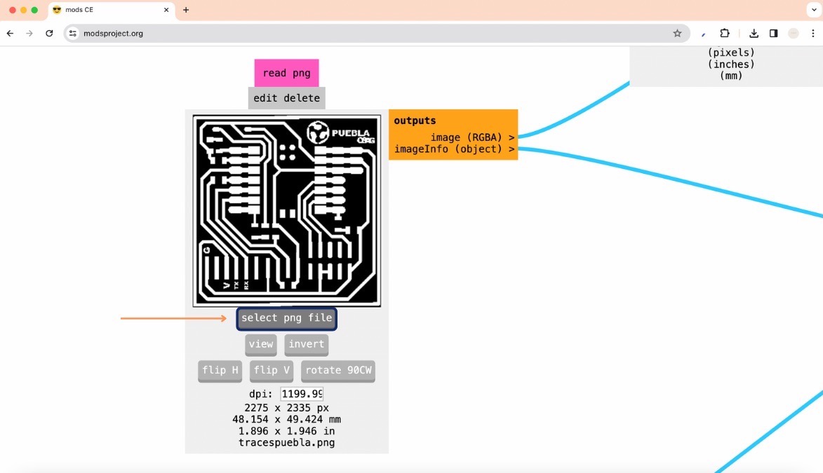
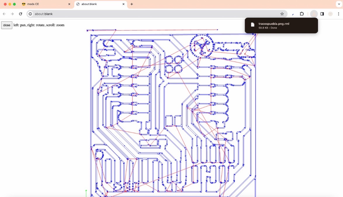
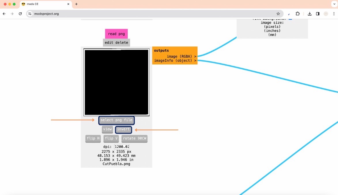
- First upload your png file, I will start by creating the file for the traces necessary for my board. Here you can find the png I used.
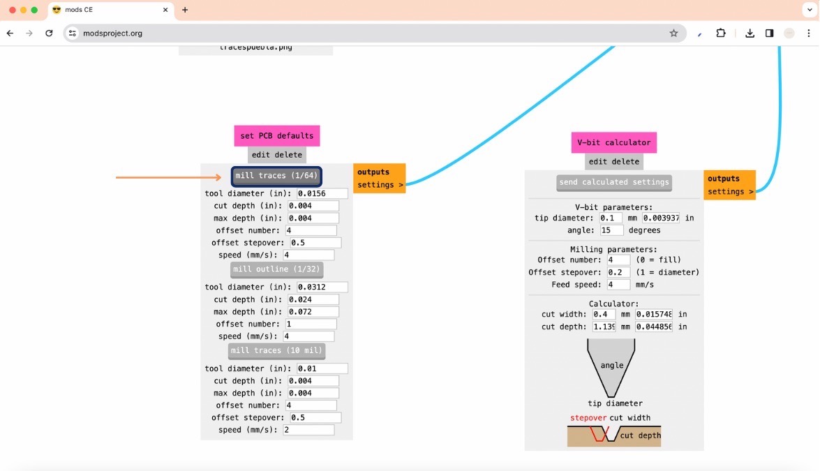
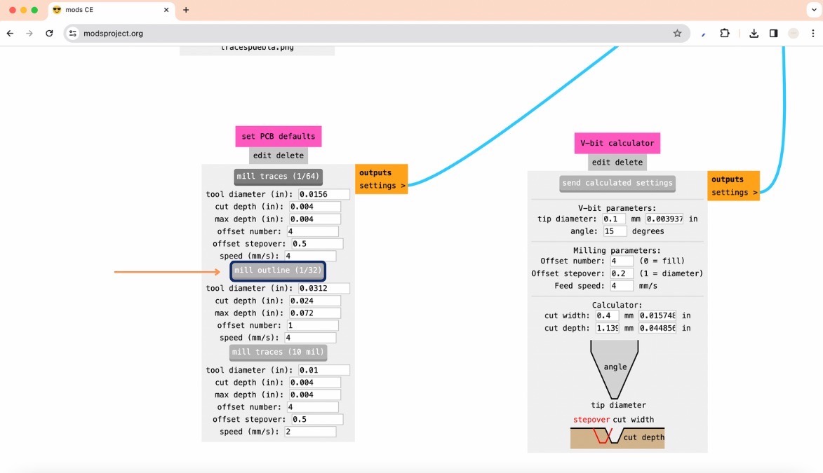
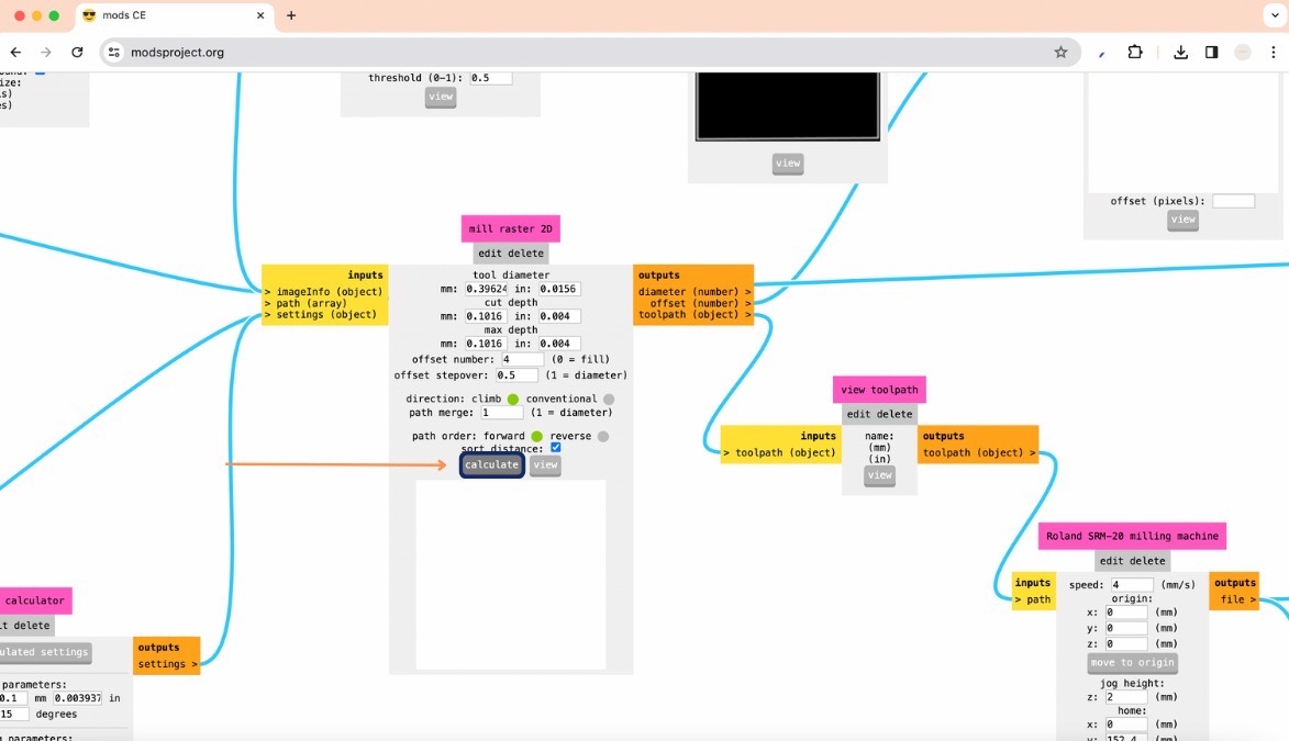
- Click on ‘mill traces’
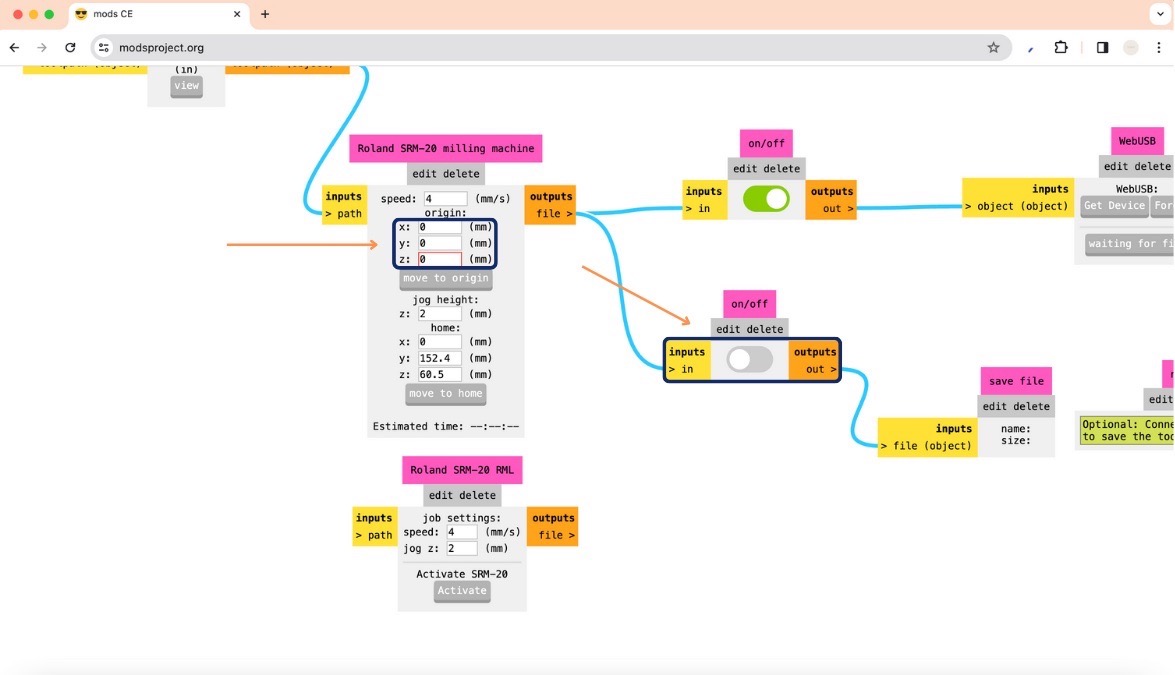
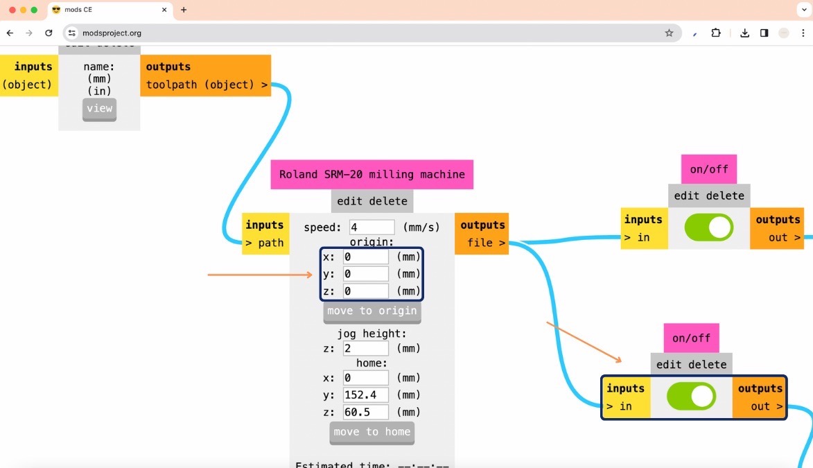
- Then change the x, y and z values to 0,0,0 to modify the origin position, and turn on the button on the right (it should look green)
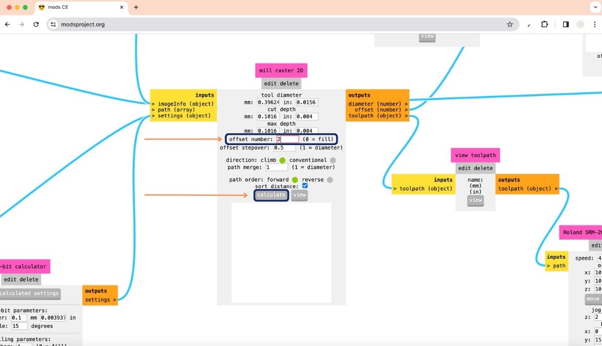
- Now, change the offset numer to 2 and click on the calculate button
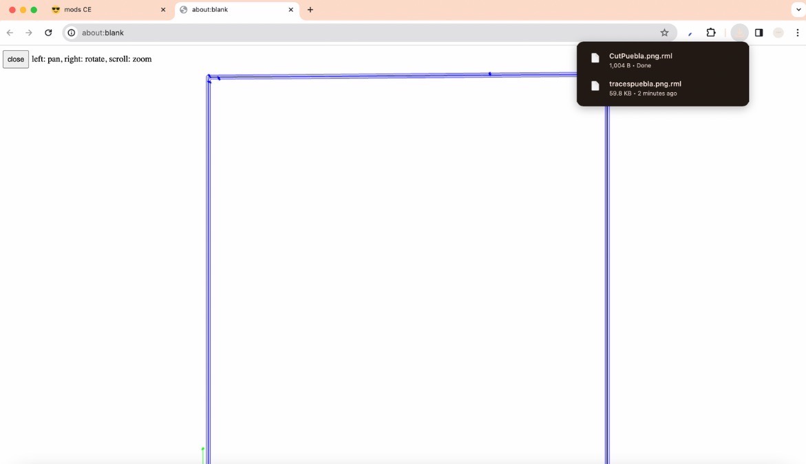
- This will immediately create your file and download it to your computer.
Now I will show you how to mill outlines:
- Repeat the first few steps to get to the initial page
- Upload your png file for the outline, but remember to invert it given that black represents what will be milled and white represents the material left
- Now click on ‘mill outline’
- Once again, change the x, y and z values to 0,0,0 to modify the origin position, and turn on the button on the right (it should look green)
- To finish, now click on the ‘calculate’ button and this will once again immediately create your file and download it to your computer
How to use the milling machine:
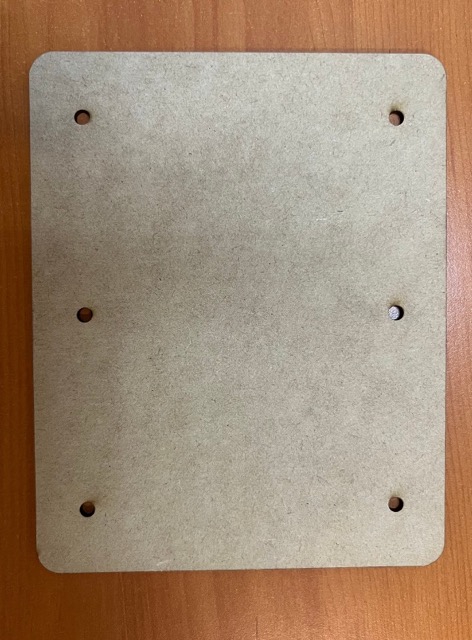
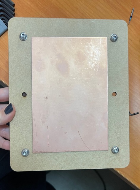
- Prepare the sacrifice board:
- It's crucial to have a sacrifice board to protect your copper board during drilling
- Cut the sacrifice board using a laser cutter
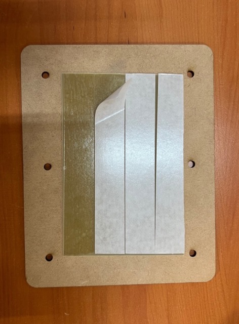
- Use double-sided tape to securely attach the copper board to the sacrifice board, ensuring that the edges are well-pasted
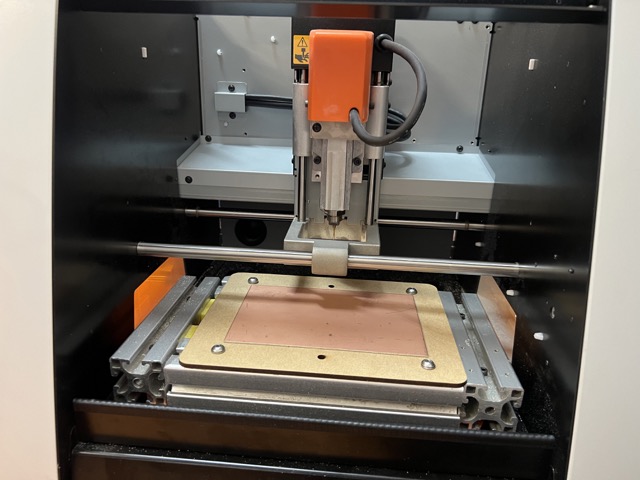
- Fix sacrifice board to the milling machine:
- Securely fix the sacrifice board, along with the copper board, to the milling machine using screws to prevent movement
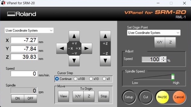
- Connect and set up:
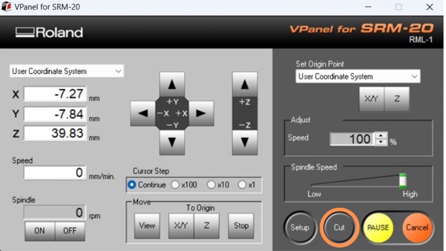
- Connect your computer to the milling machine and launch the Vpanel software
- Select drill and position:
- Choose the appropriate drill for engraving
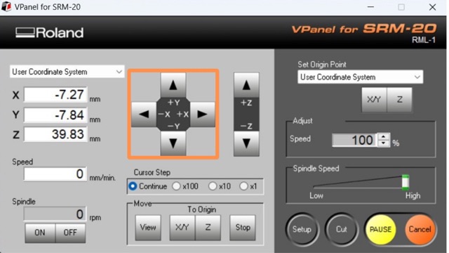
- Use the x and y buttons to position the drill at the lower left corner of the board
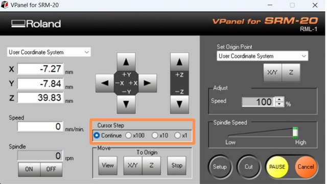
- Adjust the cursor step as needed. Continue = continuously move, x100 = 1 mm, x10 = 0.1 mm and x1 = 0.01 mm.
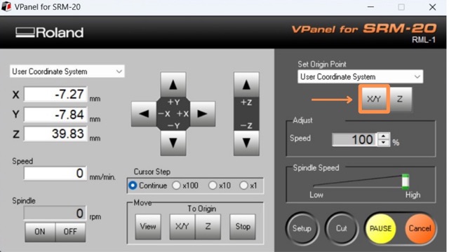
- Once you have reached the lower left corner click on the ‘set origin point’ button to set this position
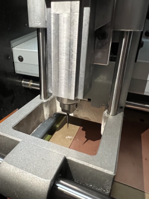
- Set Z origin:
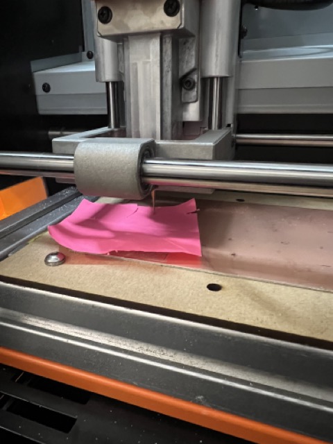
- Move the drill to the middle of the board and carefully lower it until it touches the paper
- Turn on the spindle and lower the drill by 0.1mm to ensure proper cutting depth. Set this position as the Z origin
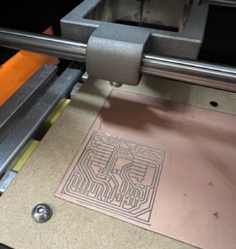
- Start milling:
- Click on the "move to x/y origin" button and stop the spindle
- Click on "cut," delete any existing files, and open the trace file created with mods, the spindle will begin automatically and start engraving your board
- Cut outline:
- Change the drill to the one used for cutting the outline of the board
- Repeat the same steps to set up the Z origin for cutting
- Click on "cut," delete any existing files, and open the cut outline file created with mods


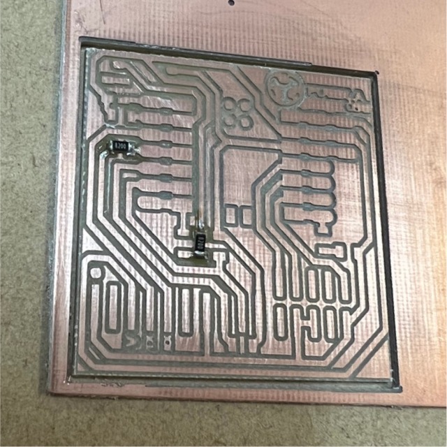
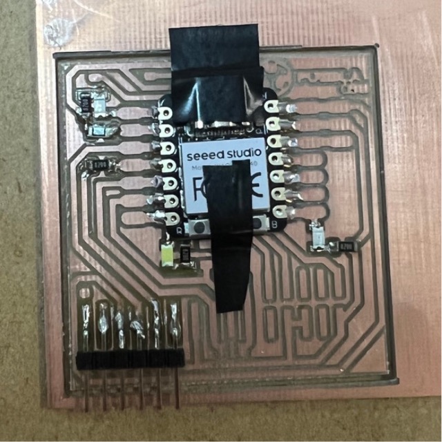
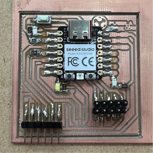
Here you can see the final result after engraving and cutting my PCB board!
Now let's start soldering!!
Components needed:
Quantity |
Component |
|---|---|
| 1 | Seeed Studio XIAO-RP2040 |
| 4 | 820 ohm resistor |
| 1 | 2.4 k ohm resistor |
| 3 | LEDS |
| 1 | Button |
| 1 | 6-pin Right-Angle SIL Headers |
| 2 | 5-pin Right-Angle SIL Headers |
| 1 | Roll of tin for soldering |
| 1 | Soldering iron |
| 1 | Tweezers |
Steps
What you should know:
- Before soldering a component, apply two small dots of solder to the soldering pads on the PCB where the component will be placed. Then hold the component in place using tweezers and melt the solder to fix the component in place.
- After soldering, inspect the solder joints to ensure good connections, if needed, reheat the solder joints and adjust the component's position to achieve a proper connection.
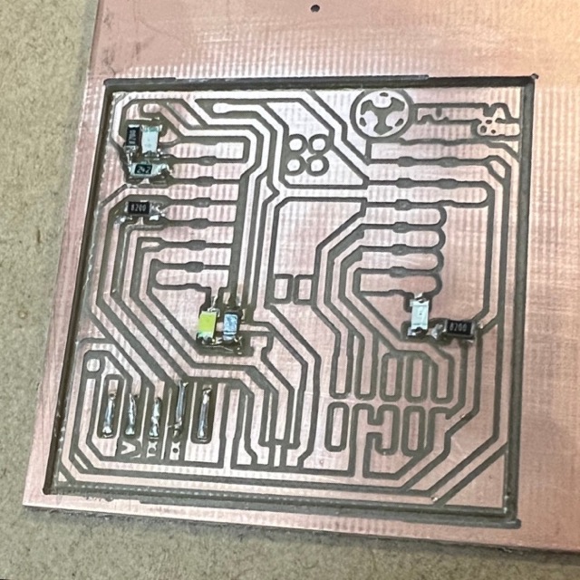
- For this process I started by soldering the resistors and LEDs first. These components are very small, and soldering them later might be challenging.
- I then proceeded to solder the pin beds and seeed studio board onto the PCB. These components are typically larger and easier to handle.
Tips
- Patience
- Use tweezers for precision
Board programming
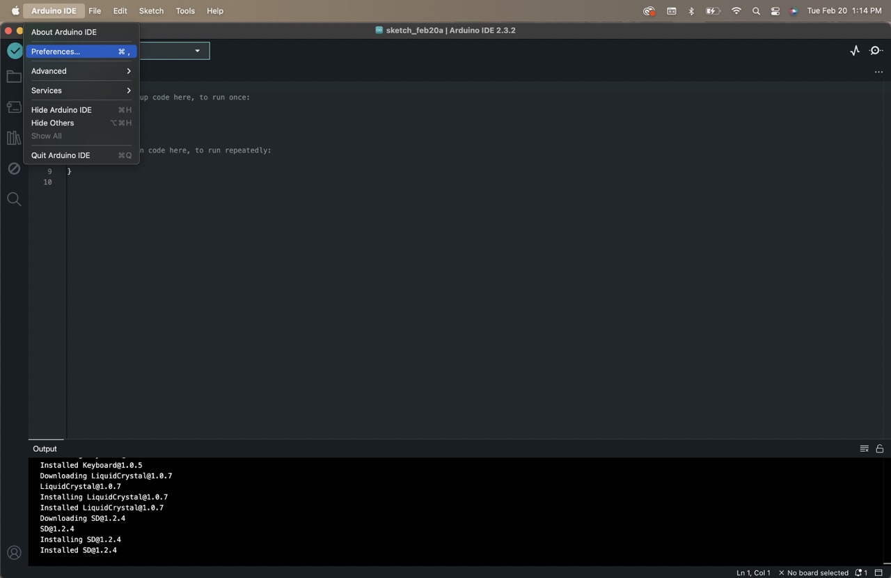
Now to test if the pcb board was working correctly I uploaded the following code given by our instructors to the seeed studio board. To do this I used the arduino IDE platform.
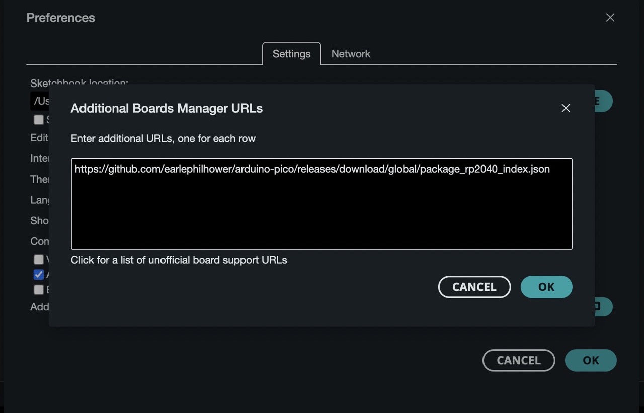
To begin, I added the Seeed Studio XIAO RP2040 board package to my Arduino IDE following this tutorial, here you can see the steps:
- Go to ‘Preferences’ and under ‘Aditional boards manager URLs’ copy and paste the following link: https://github.com/earlephilhower/arduino-pico/releases/download/global/package_rp2040_index.json
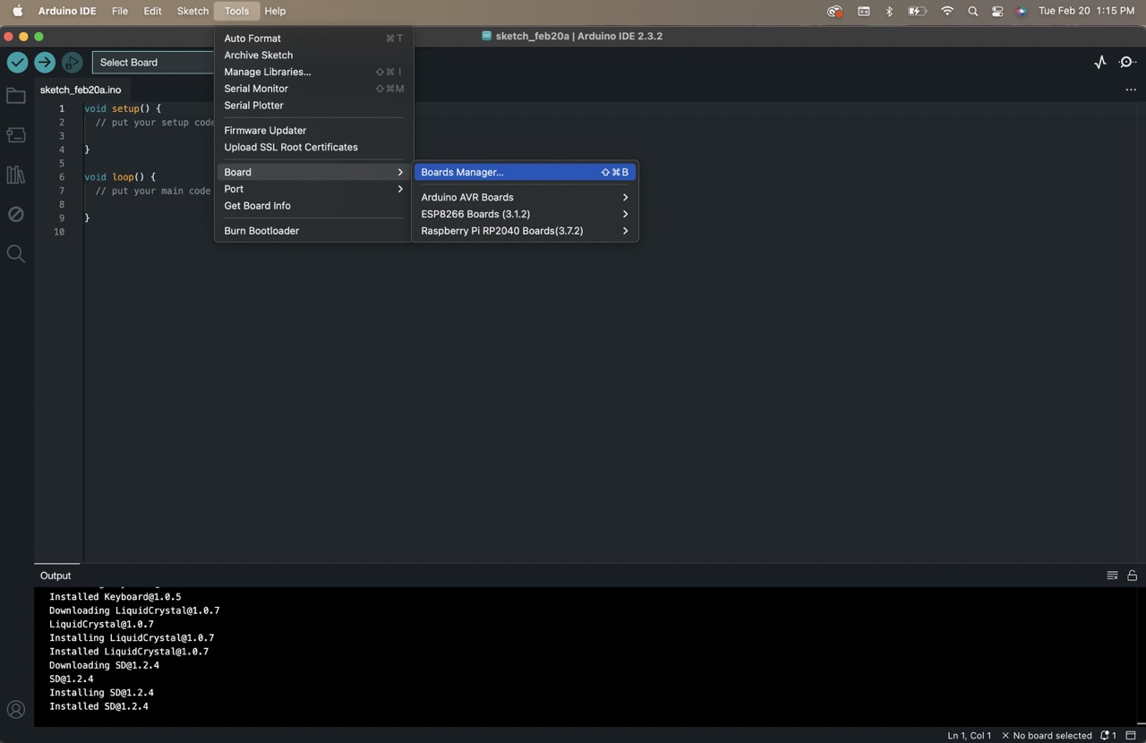
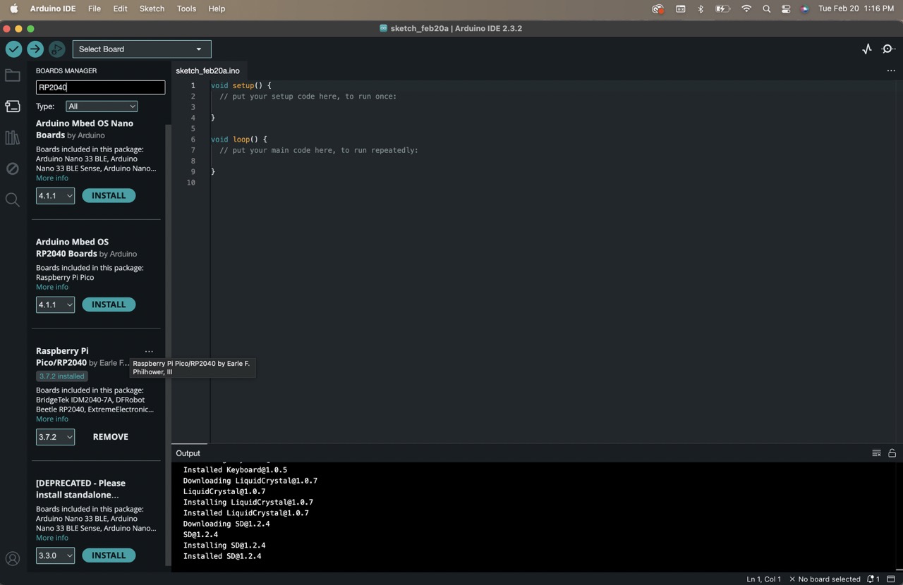
- Then under Tools > Boards > Board Manager type in ‘RP2040’ select ‘Raspberry Pi Pico/RP2040’ and install it
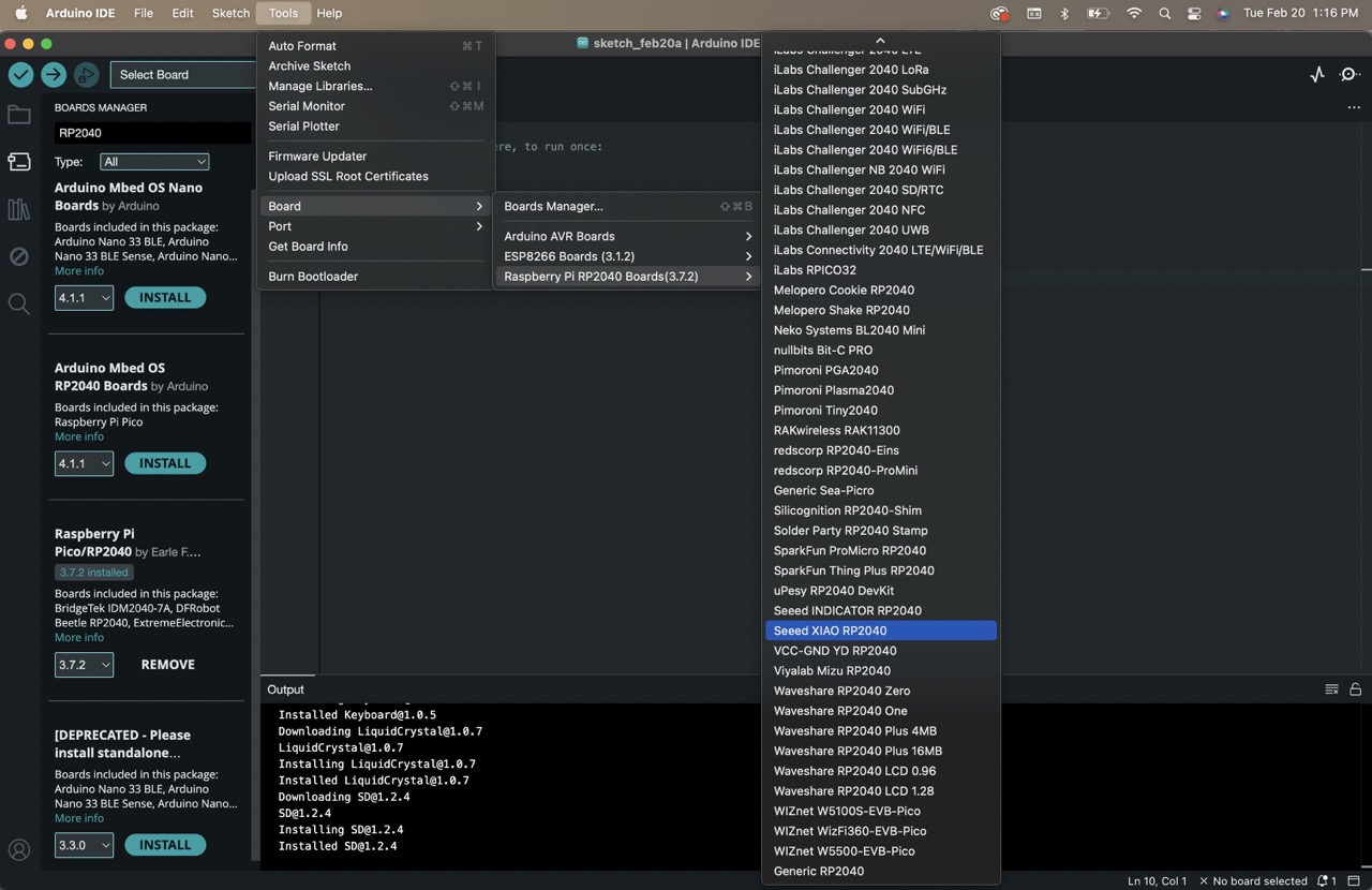
- Select your board
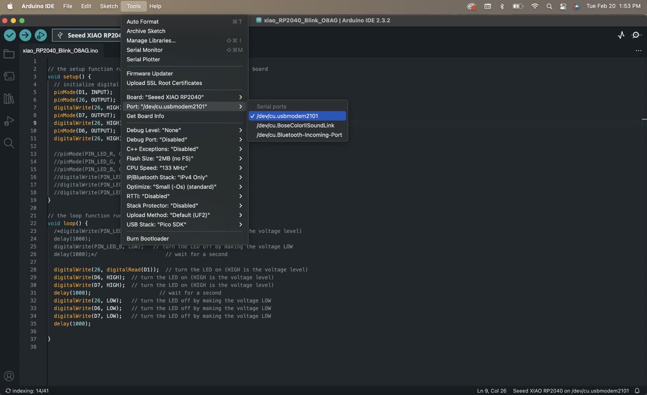
- Identify and select your port
- Upload the code to the and test it to see if it works correctly
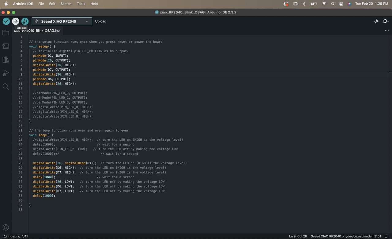
Here you can see how the board works with the uploaded code. The orange and white LEDs light up simultaneously and when the button is pressed, the green one lights up as well.