INPUT Devices
For this weeks assigment we probe an analog and digital input; the Sparkfun AD8232 Heart Rate Monitor as the anlog and the MAX30102Blood Oxygen Sensor Pulse for the digital. For a detailed explanation, go to the group's assigment
What are INPUTS?
nputs refer to signals or data received by a microcontroller or computer from external devices. These inputs can come from various sensors, buttons, switches, or other components that provide information about the external environment. Inputs allow the microcontroller to make decisions and perform actions based on the data it receives, such as reading the temperature from a sensor, detecting the state of a button press, or measuring light intensity with a photoresistor. Inputs are essential for creating interactive and responsive electronic projects.
PCB
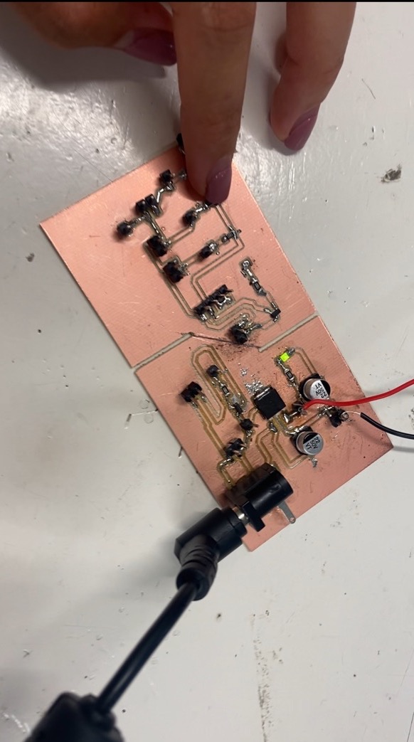
For this assignment, I used the PCB I had previously designed in week 9. You can find more information about its design and milling process on that week's page.

Photoresistor
I decided to program a photoresistor for this assignment since I find it very useful for various electronic projects.But first of all, What is a photoresistor and how does it work?
A photoresistor, also known as a light-dependent resistor (LDR), is a sensor that changes its resistance based on the amount of light it is exposed to. In bright light, its resistance decreases, allowing more current to pass through, while in darkness, its resistance increases, reducing the current flow. This characteristic makes it useful for detecting light levels and triggering actions in electronic circuits based on ambient light conditions.
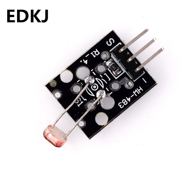
I used the photoresistor KY-018
It´s parameters are:
- comparator output, signal clean, good waveform, strong driving capacity, more than 15mA
- operating voltage 3.3V-5V
- output form: digital switch output (O_D) or analog switch output (O_A)
- small board PCB size: 2.6cm x 1.6cm
Coding
First, I tested the photoresistor using the following code to determine the values for low and high resistance. By turning the light on and off and documenting the values, I can later decide how to use them in my project.

From this test I determined that when the light was on the value was about 600-300 and when the light was off it was 1023. Based on this, I wrote a code that turns the NeoPixel ring green when the light is on and red when the light is off.
Result
Measuring the photoresistor with an oscilloscope
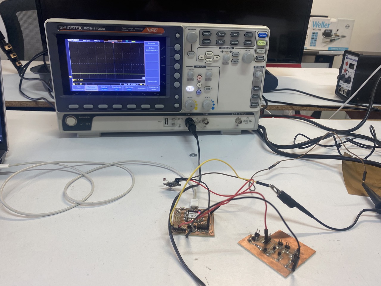
To use the oscilloscope, I first ensured that the photoresistor was properly connected to my PCB. Then, I connected the oscilloscope tip to the data pin of the photoresistor. Finally, I adjusted the oscilloscope to the correct scale and voltage. For this part of the assignment, my teacher Oliver helped me out since I had never used an oscilloscope before.
INPUT vs. OUTPUT values
To gain a better understanding of how the photoresistor measures light, I decided to create a graph that plots the light intensity (in lux) against the resistance measured by the photoresistor.
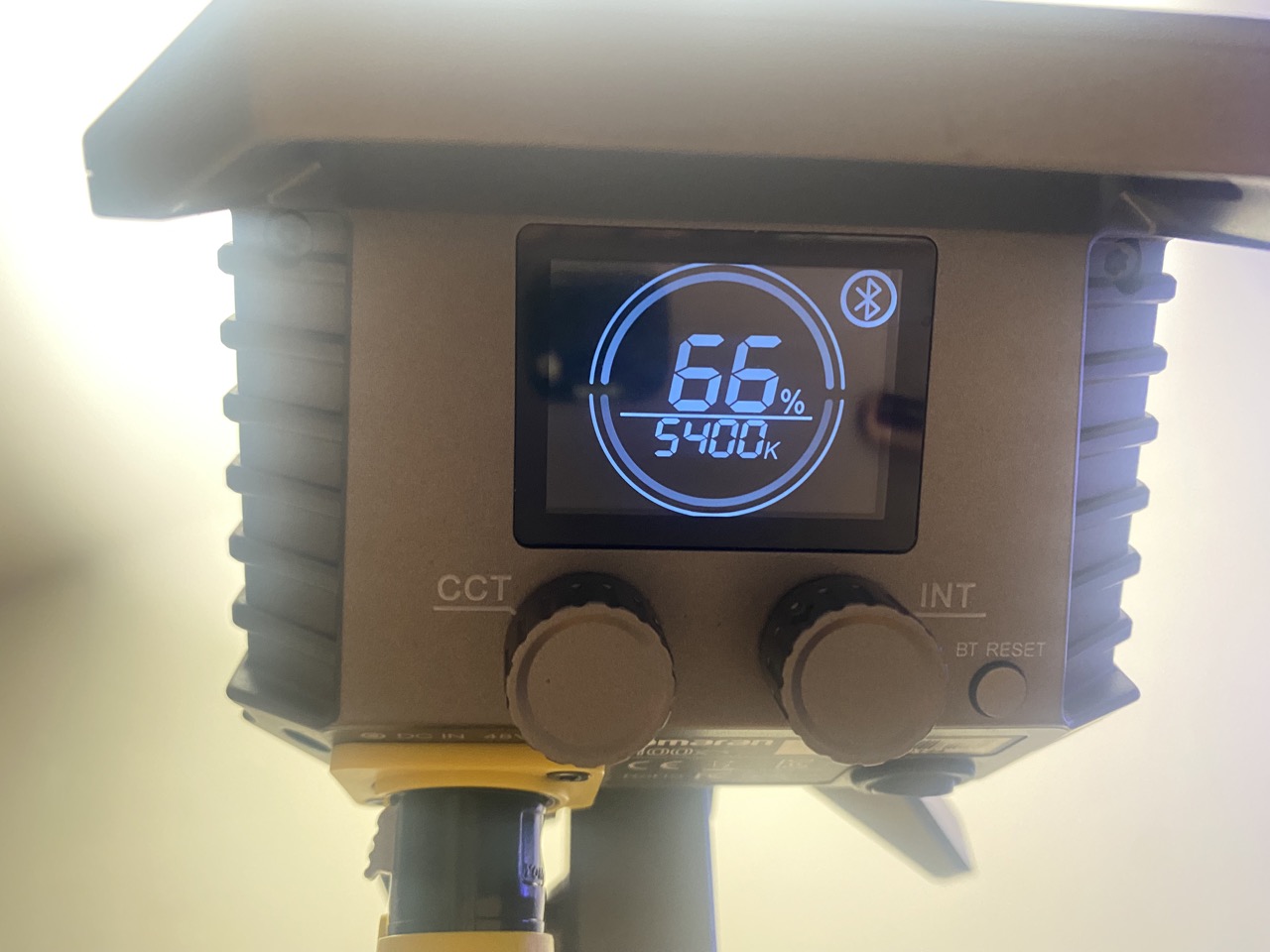
For this, I used a photography light (the Aputure Amaran 100k), which allows for adjusting both the intensity and temperature of the light. Using this light was really useful for achieving different light intensities that a regular bulb wouldn't be able to provide.

To measure the intensity of the light, I used my phone by downloading an app called Light Meterlink to the app I decided to use an app since we didn't have a lux meter at the university. I used this app by changing the intensity of the light by 10% increments each time and measuring the light intensity. I recorded these values for further analysis.
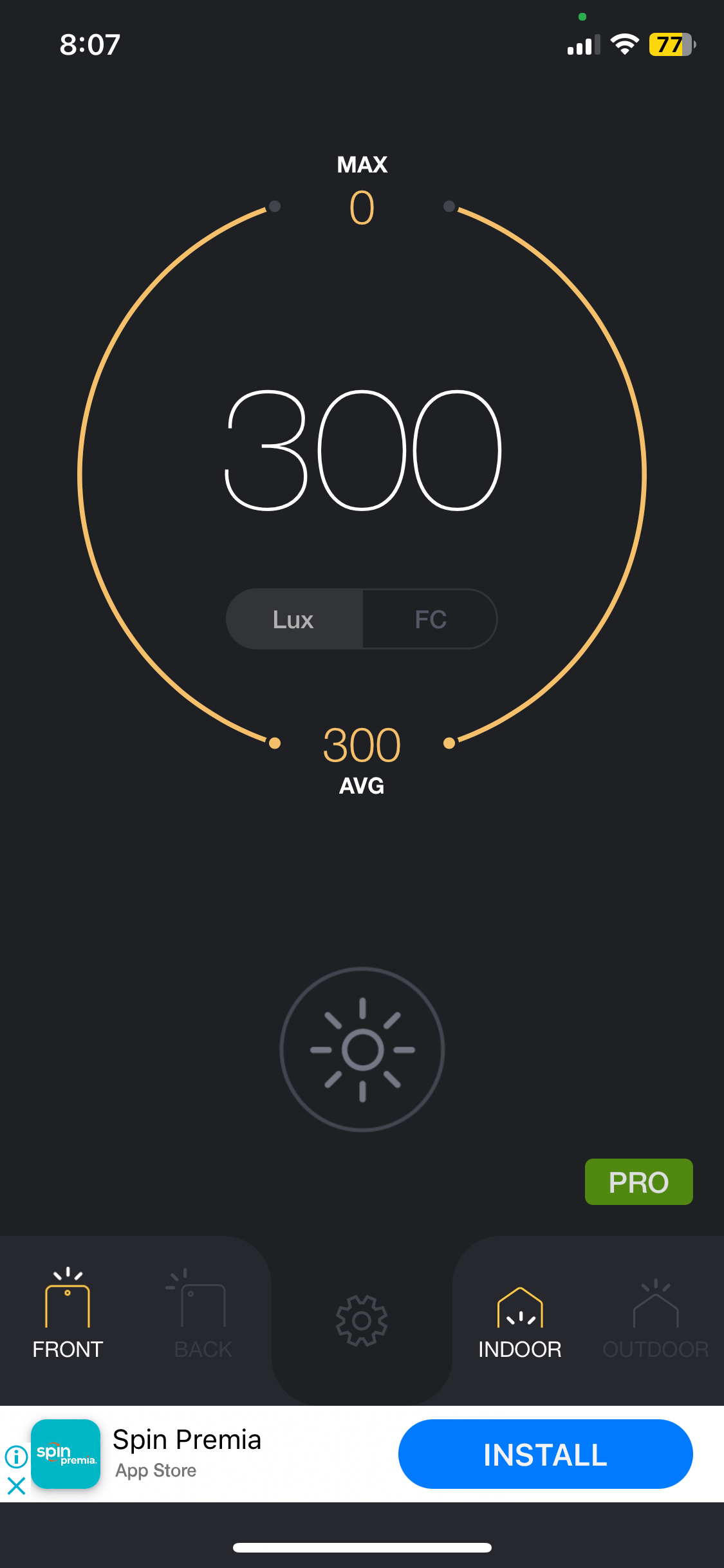
Arduino I used a simple code in Arduino so that the photoresistor would print the value of the light's resistance. I then recorded these values to use for the graph.

In Excel I created a chart with three columns: the first indicating the percentage of light intensity set on the light for reference, the second for the lux measurement taken by the app, and the third for the resistance value measured by the Arduino IDE. From this chart, I created an XY graph using just the two columns for lux and resistance.


From this graph, I observed that as the intensity of the light increases, the resistance of the photoresistor decreases.
A brief reflection of the week
It sounds like you navigated through some common challenges when working with photoresistors and analog inputs. Understanding how the sensor values correspond to light levels is crucial. If you need any more assistance or have further questions as you continue your project, feel free to ask!
WHAT I LEARNED FROM THIS ASSIGMENT
I learned that a photoresistor is considered an analog sensor because it produces a continuous range of resistance values depending on the light intensity it detects. I also learned that unlike digital sensors, which provide binary outputs (on/off), an analog sensor like a photoresistor varies its resistance proportionally with the light levels, resulting in a variable voltage when used in a circuit.
