OUTPUT Devices
For this week's assignment, I decided to try programming an OLED display. I was initially worried because it seemed difficult, but it turned out to be quite fun. To learn more about OUTPUT devices I'll leave the group's assigment.
What are OUTPUTS?
In electronics and programming, outputs refer to the signals or data sent from a microcontroller or computer to control external devices. These can include digital outputs, which are either HIGH (on) or LOW (off) signals used to control LEDs, relays, or motors, and analog outputs, which vary within a range to control things like servo motors or LED brightness. Additionally, outputs can involve sending information to displays like OLEDs or LCDs to show text or graphics. Pulse Width Modulation (PWM) outputs are also common, simulating analog control by rapidly switching between HIGH and LOW states to adjust motor speed or LED brightness. Outputs are crucial for creating interactive projects, providing feedback, controlling components, and displaying information to the user.
Designing a new board
So I took advantage of this assignment and decided to start designing my final project's PCB. This way, I have enough time to test it and correct any mistakes if needed.
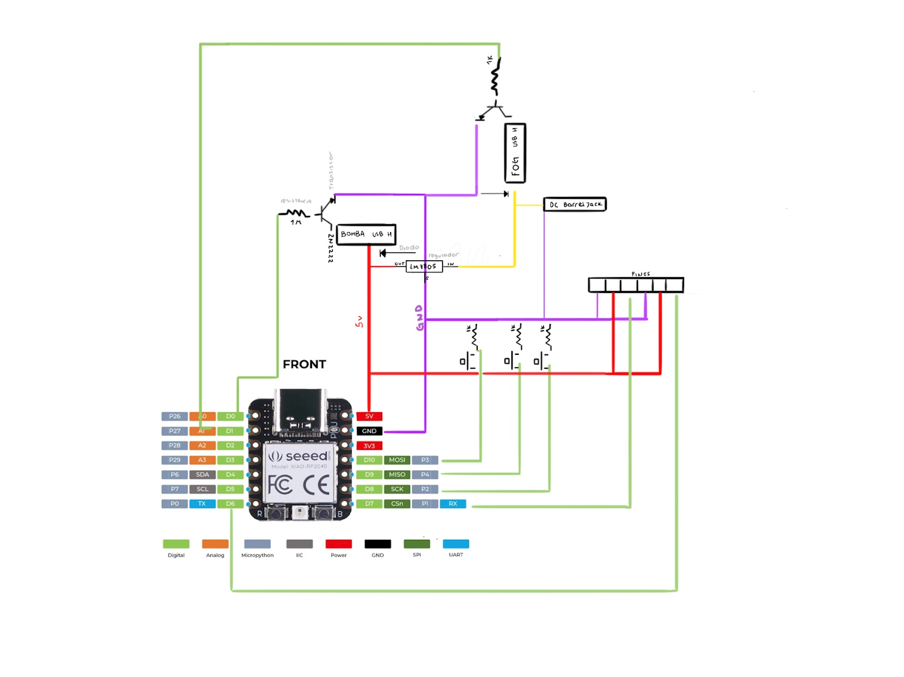
For my final project, I want the PCB to be able to control a ring of NeoPixels, a water pump, and an ultrasonic mist maker. To achieve this, I need to manage two different voltages: 5V for the microcontroller, NeoPixels, and water pump; and 24V for the ultrasonic mist maker.
For the PCB I used the following electrical components:
- Water pump: 4.5 V, 0.18 A
- Ultrasonic mist maker: 24 V, 700 mA
- Neopixel ring: 16 neopixels, 18 mA pear neopixel
- Resistors: 1m and 1K
- Diode Schottky 20V 1A SMD MBR120LSF
- Transistor:NPN 1.5A 25V SS8050
- Microcontroller Xiao rp2040
- Button:
- Regulator:Lm7805
- Pins
- 24 V ppower source
Before using a software to design the board I sketched it first in Procreate.
EASY EDA
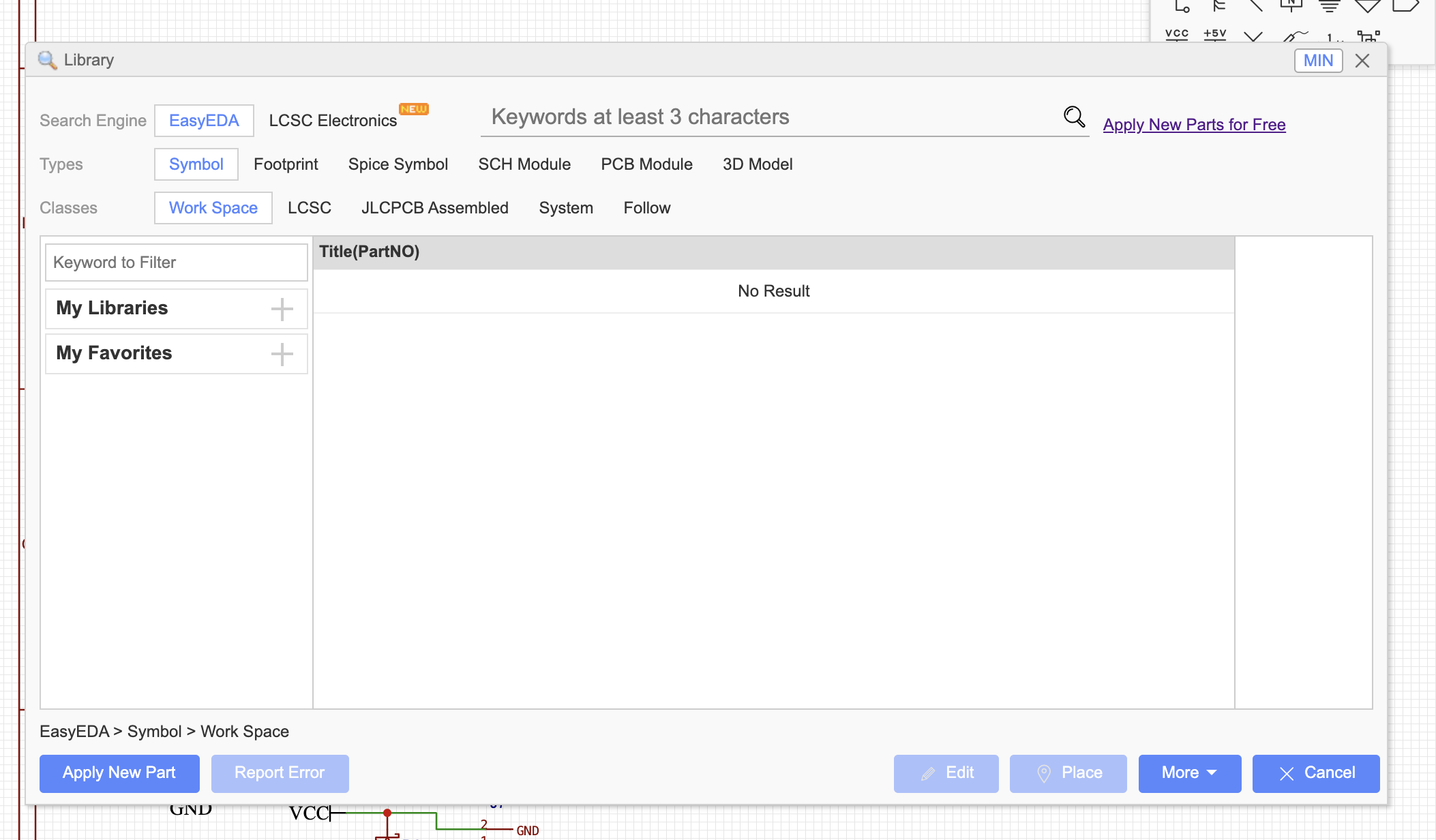
To learn how to use different software, I decided to design the PCB in EasyEDA.I started by creating a new schematic sketch and used the online library to find the right components.
Then I used the "wiring tools" to connect all the components to voltage and ground and to each other
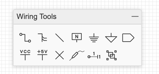
I decided to divide the 24v components and the 5v ones to prevent anything from happening.
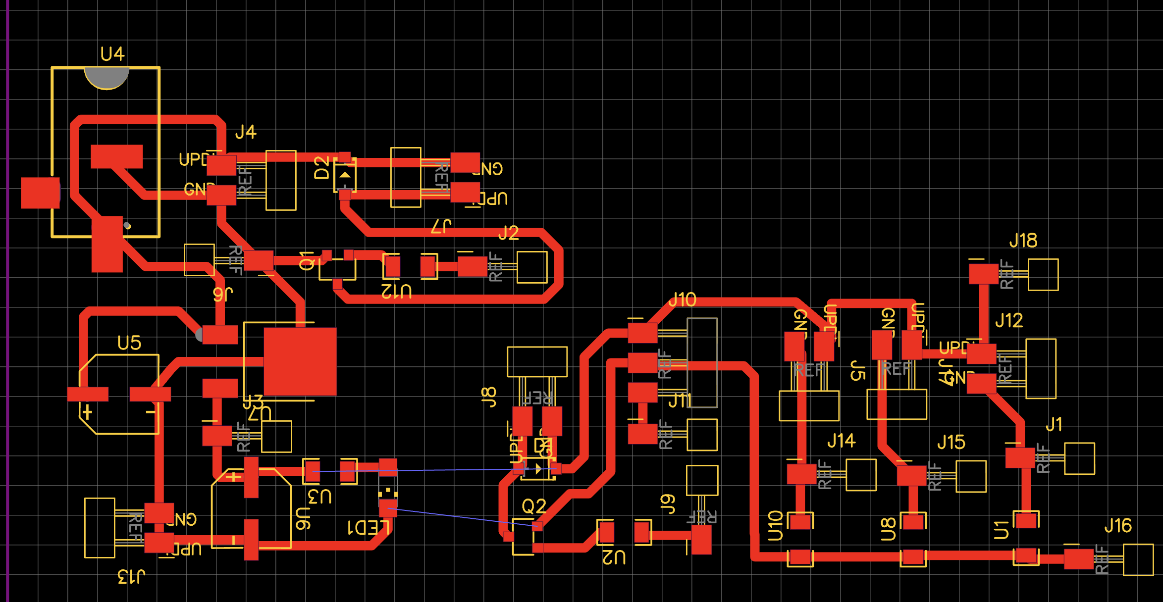
PCB design
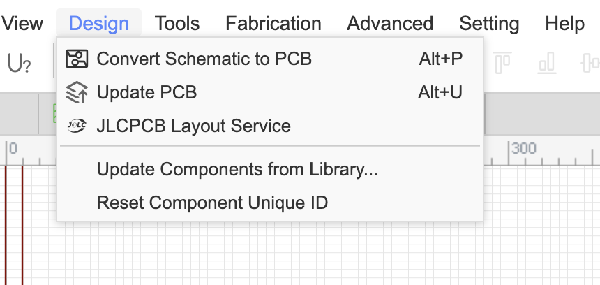
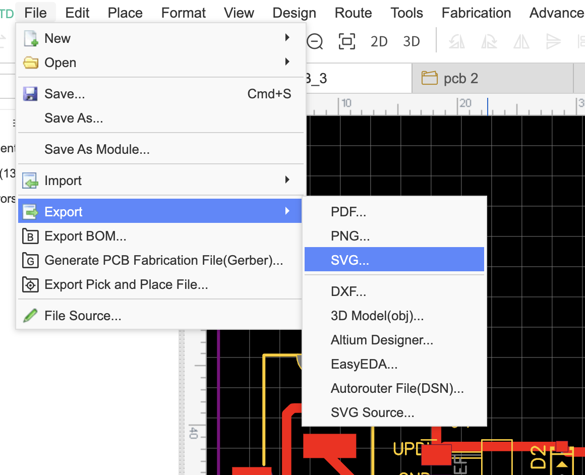
Once I finished the schematic, I clicked on "Design" and then "Convert Schematic to PCB" to start laying out the physical design and finally exported it as an SVG.
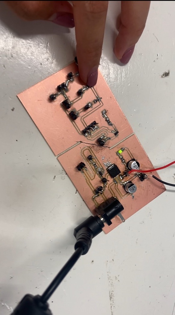
Milling and soldering the board
For explanation on how to prepare the PCB file for cutting pleaso go back to my week's 8 assigment
Experimenting with the Oled
Setting up Arduino IDE
| Step | Photo | Description |
|---|---|---|
| 1. | 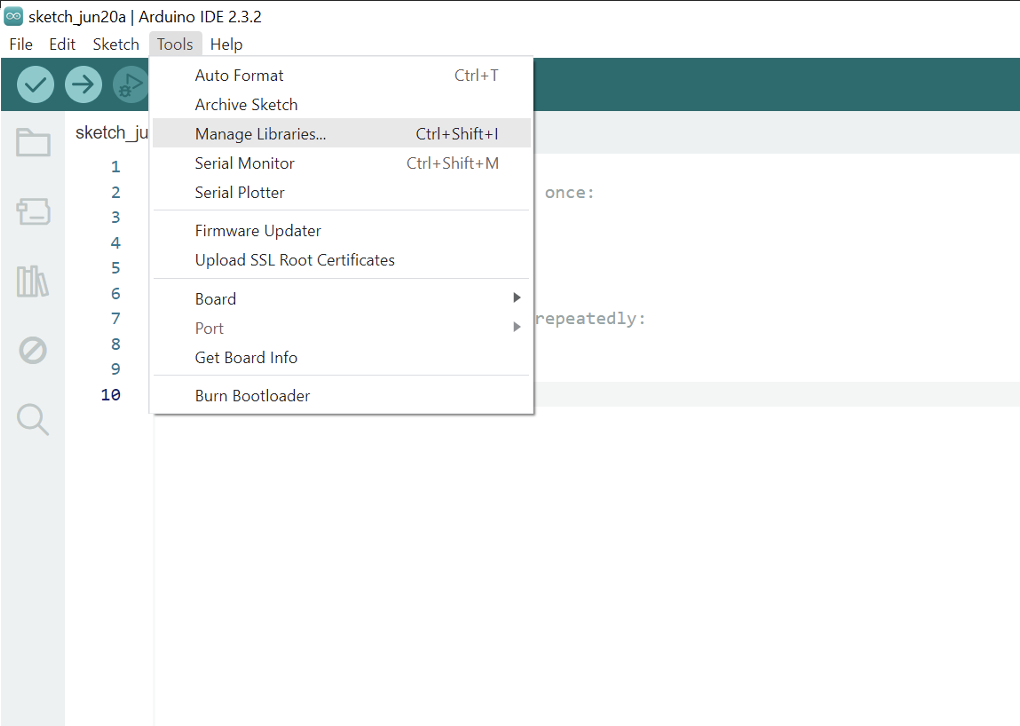
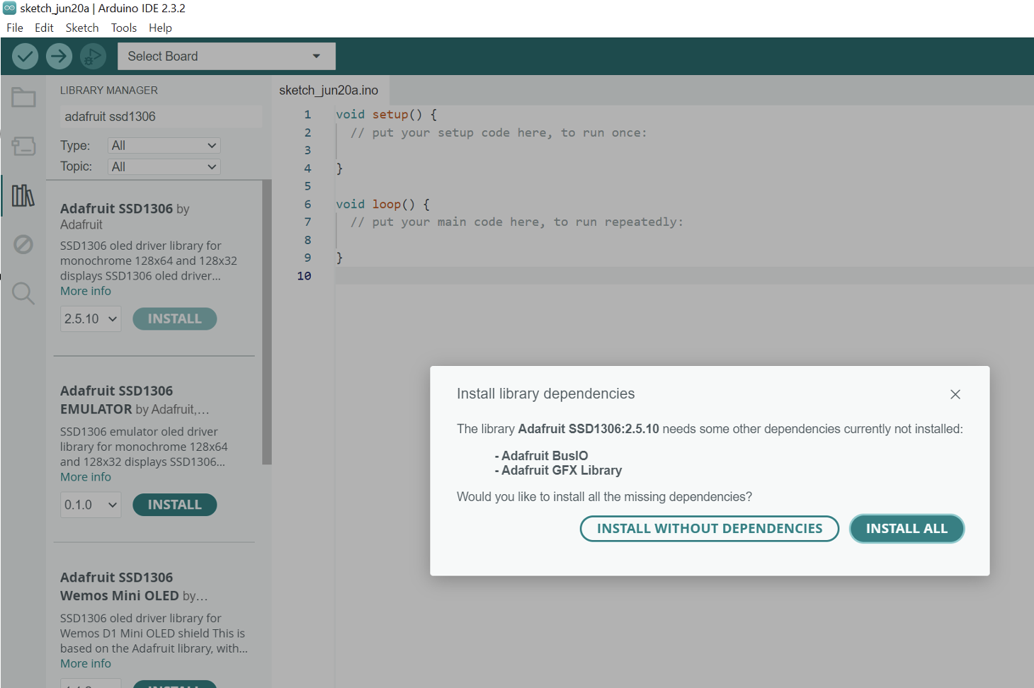 |
Selected 'Tools'. Clicked on 'Manage Libraries' and downloaded 'Adafruit SSD1306' and 'Adafruit GFX'. |
| 2. | 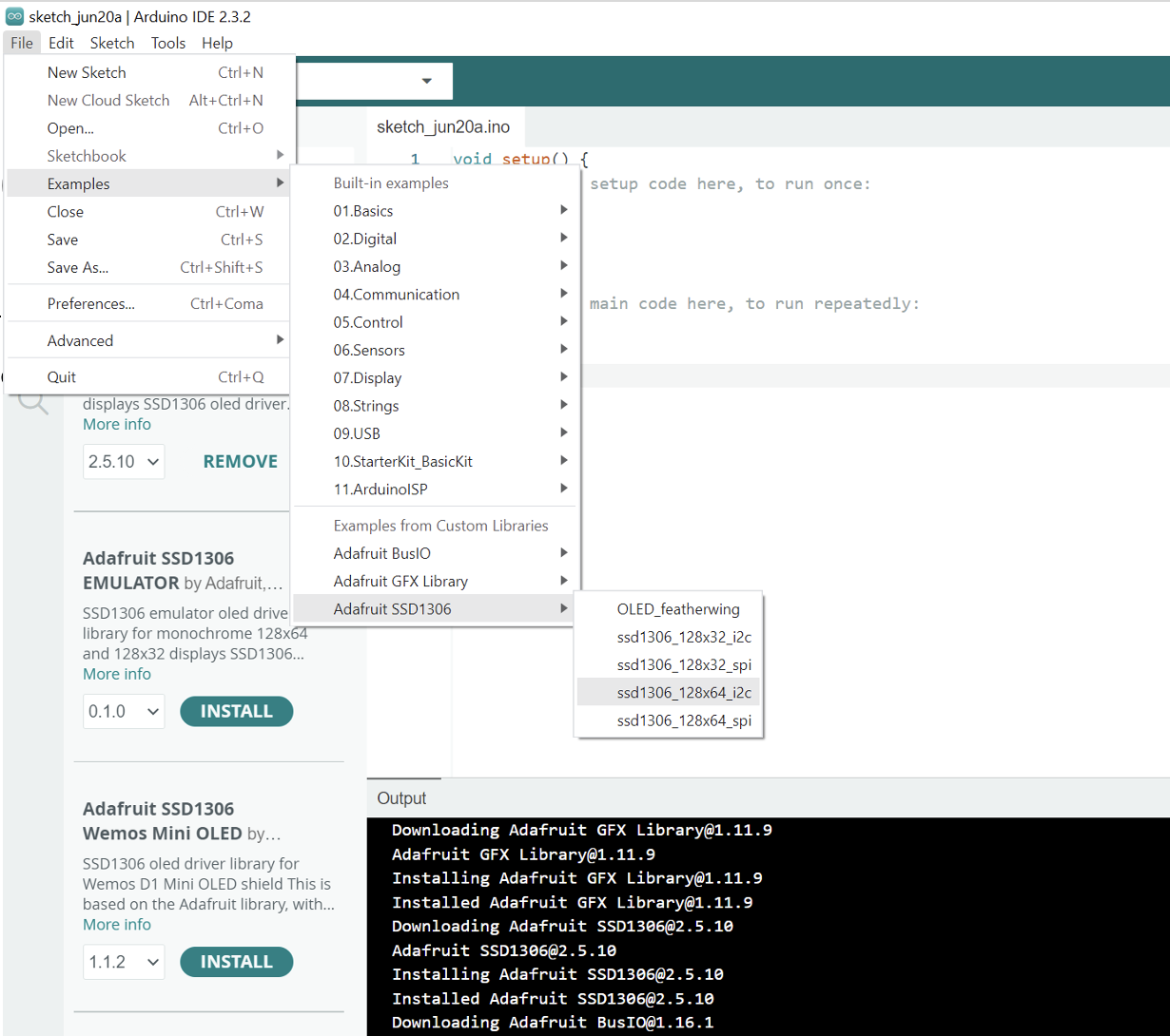 |
In examples, scroll down to 'Adafruit SSD1306' and select 'ssd1306_128x64_i2c'. |
| 3. | 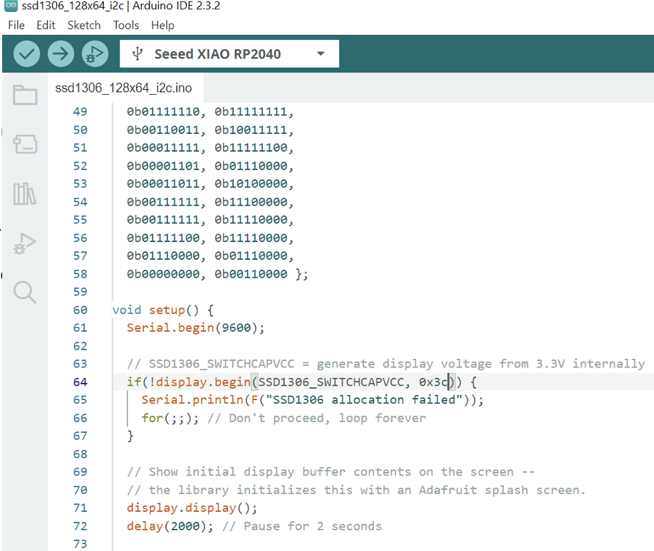 |
If it didn't work you have to change the ‘SCREEN_ADDRESS’ to ‘0x3C’ and it worked! |
Result
TEXT
To experiment I decided to test with text in the Oled. For that I used the following code.
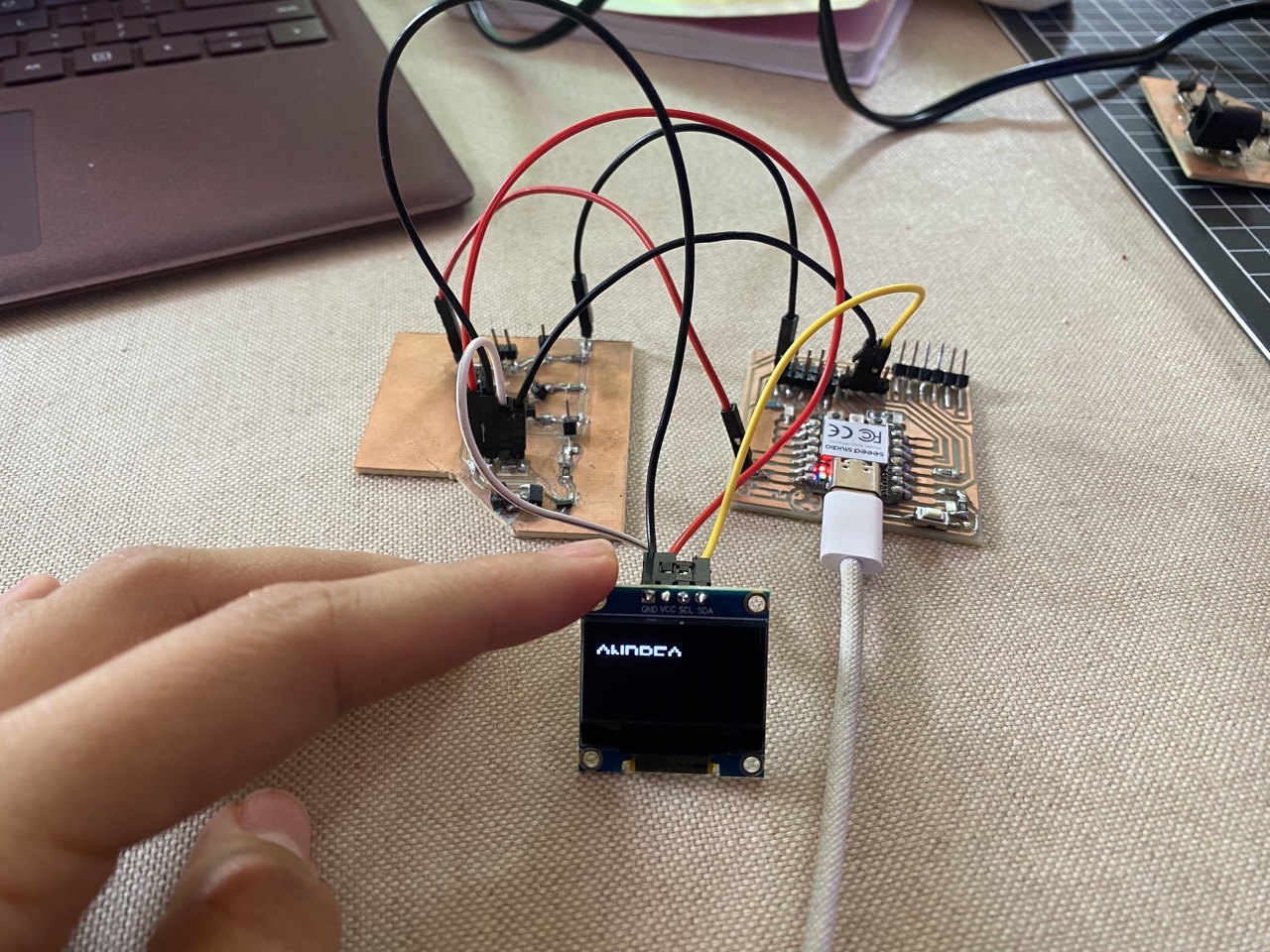
Animation
I tried to create my own animation for this assignment. To do that, I started by drawing the animation in Procreate, adjusting the document size to 128 x 64 pixels to match the OLEDs size.


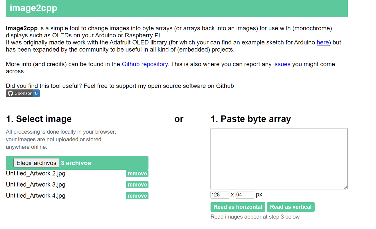
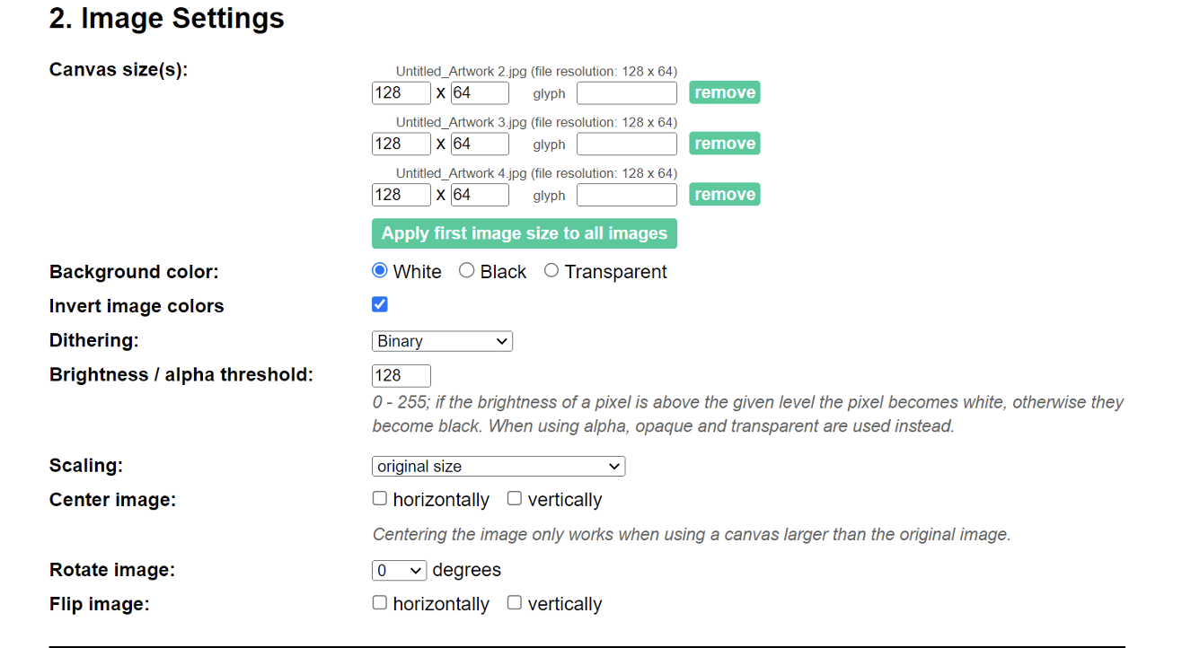
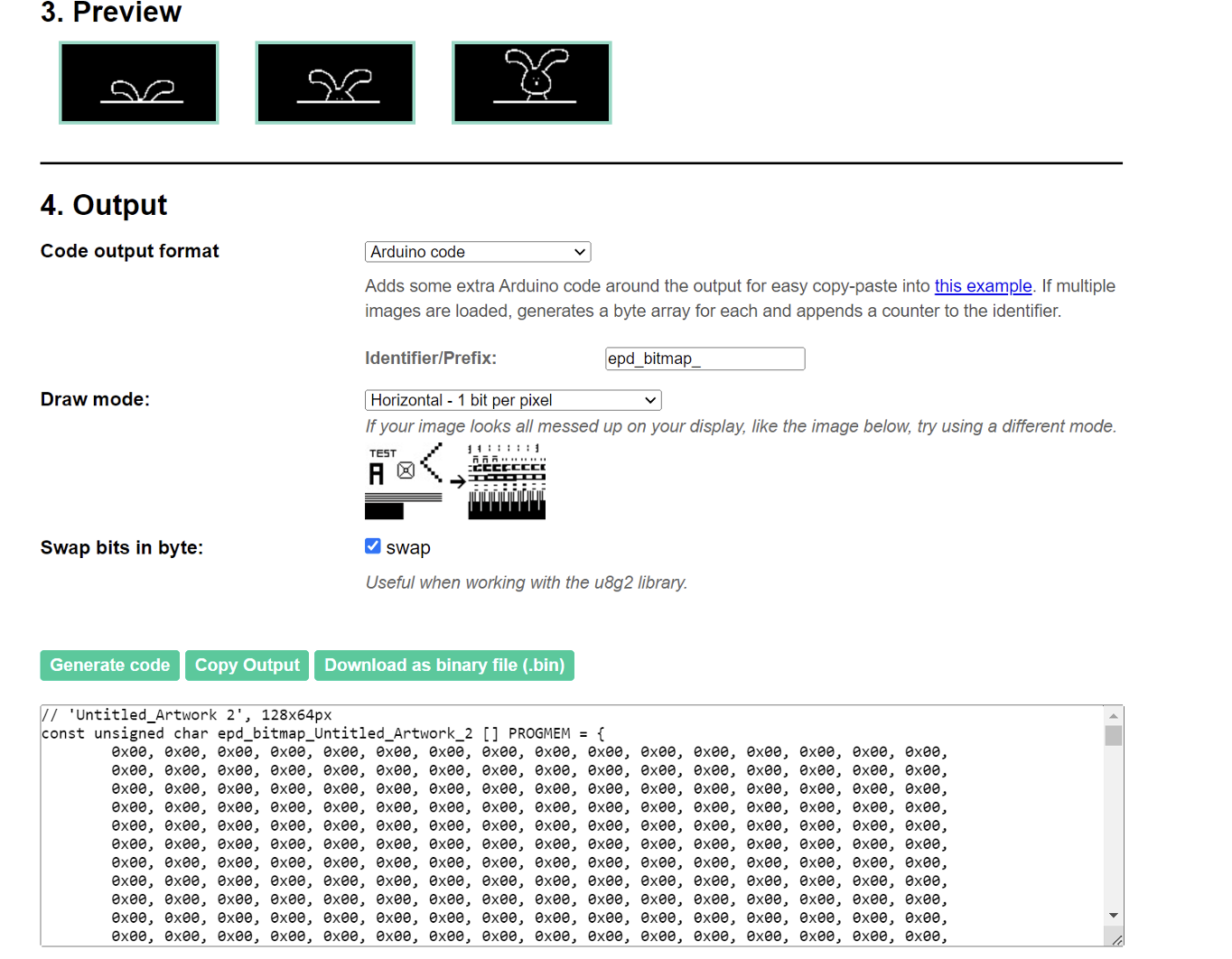
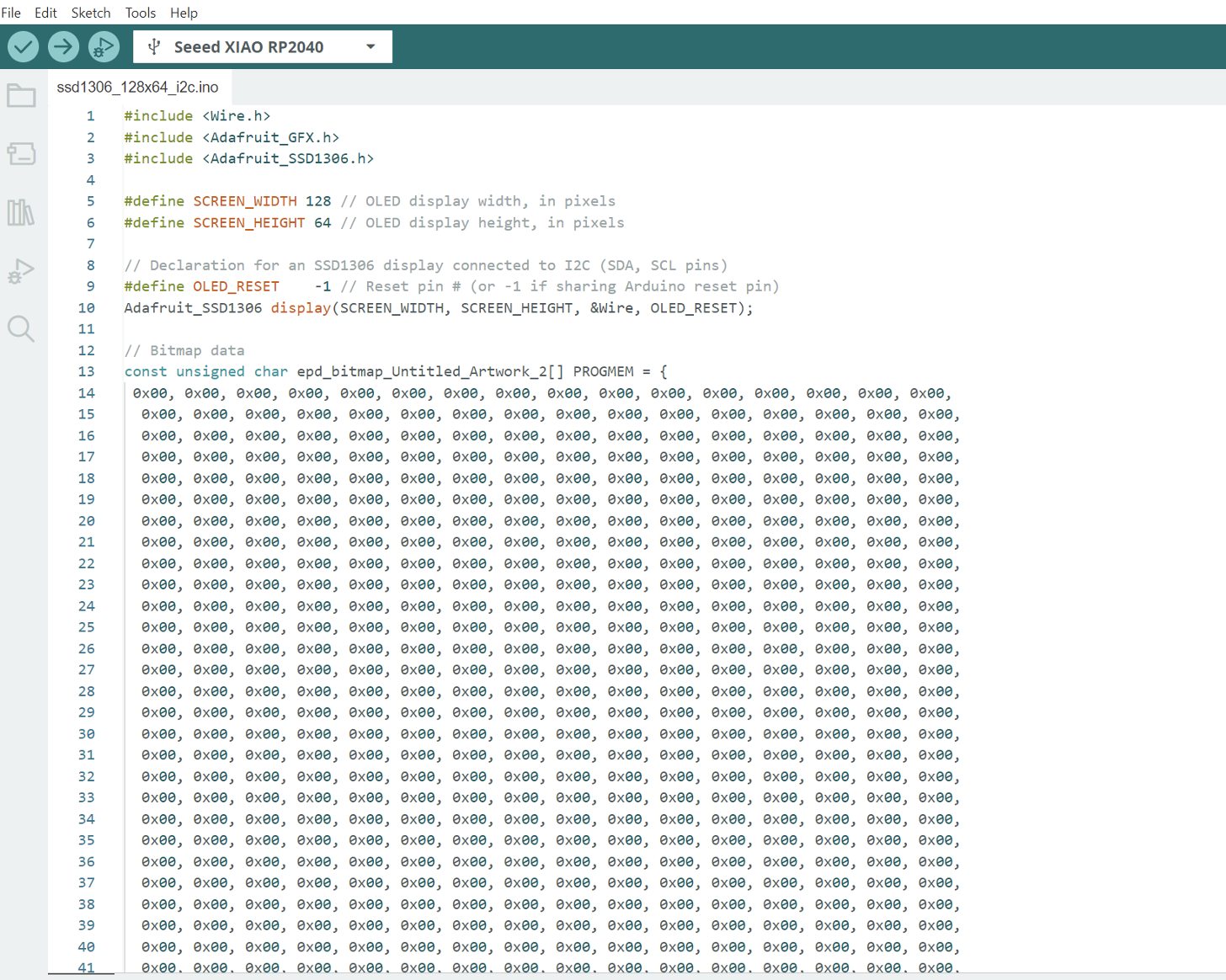
Then to convert the image to bytes I used the following online site, where I uploaded the 3 images. I made sure the size was correct, that it was in binary and that Arduino code was selected. Then I selected generate code and copied it and pasted it in Arduino IDE.
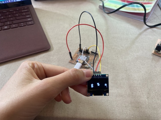
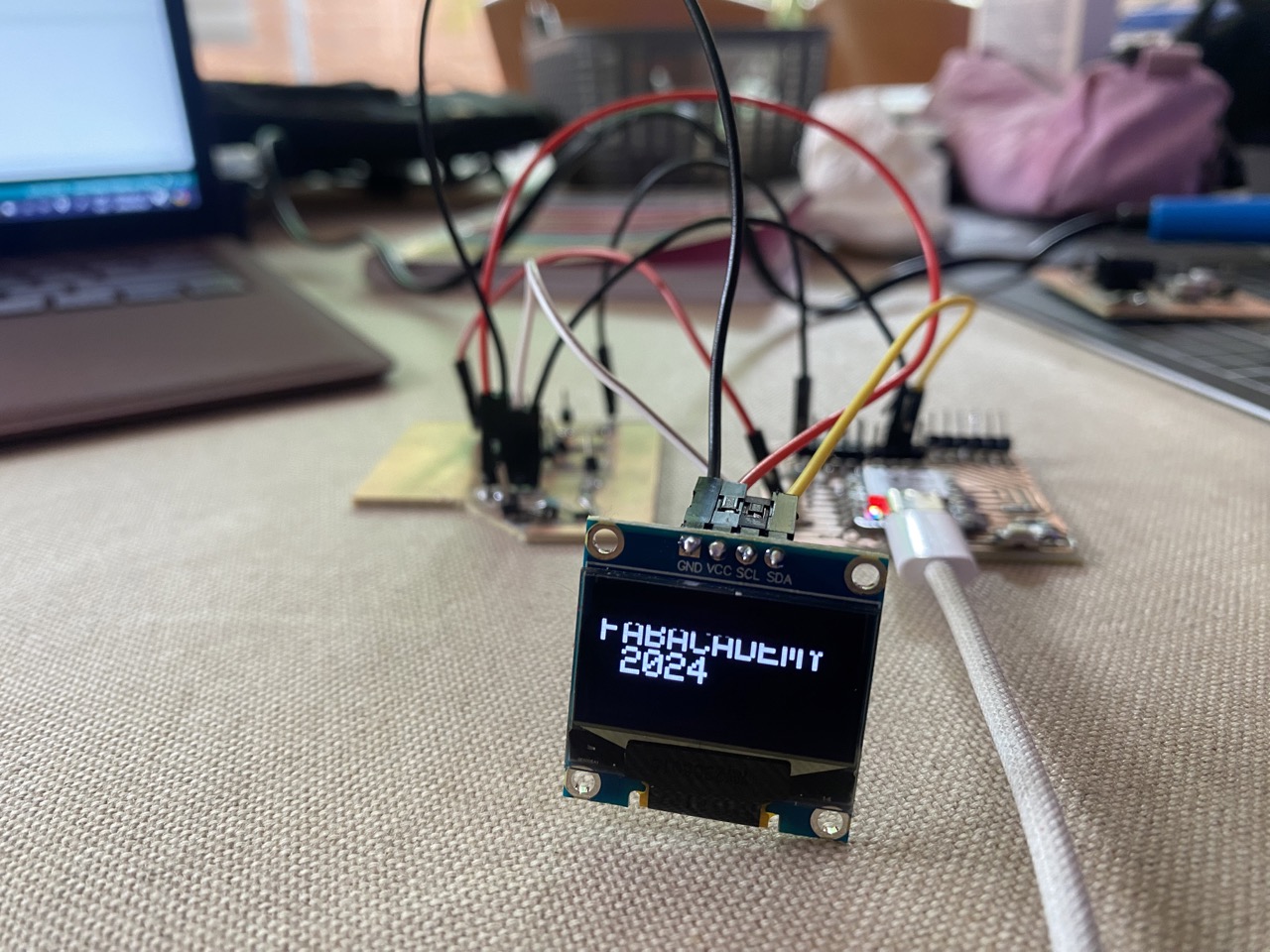
Result
A brief reflection of the week
Learning how to program outputs is really important since most electronic projects include them. Using an OLED for the first time was actually not that hard, thanks to the many tutorials and information available online. Initially, my code wasn't working because I had connected the OLED to a digital pin instead of an analog one. Once I corrected that, it worked fine. I enjoyed creating my own animation, and drawing it in Procreate was a fun experience. The hardest part was designing the board, as it took a long time to get it right. However, this was mainly because I wanted it to be perfect for my final project.
WHAT I LEARNED FROM THIS ASSIGMENT
I discovered that programming an OLED is not as hard as it looks, although I only did basic programming. I learned that it's best to use the example codes in Arduino first to ensure everything is working correctly and that the output is connected to the right pin. This approach helps because it ensures that the problem isn't in the code. If you don't do this first, it will be harder to pinpoint where the issue lies. I had some setbacks while coding, such as making mistakes with the semicolons, but thanks to Arduino's error corrections, I was able to figure it out. It was nice to finally understand the difference between inputs and outputs, and I think it wasn't until I programmed the OLED that I fully grasped it.