WHICH IS WHAT I WILL DO
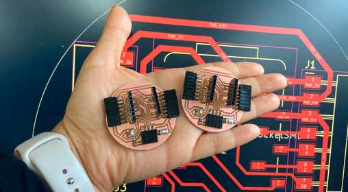
I will create two boards
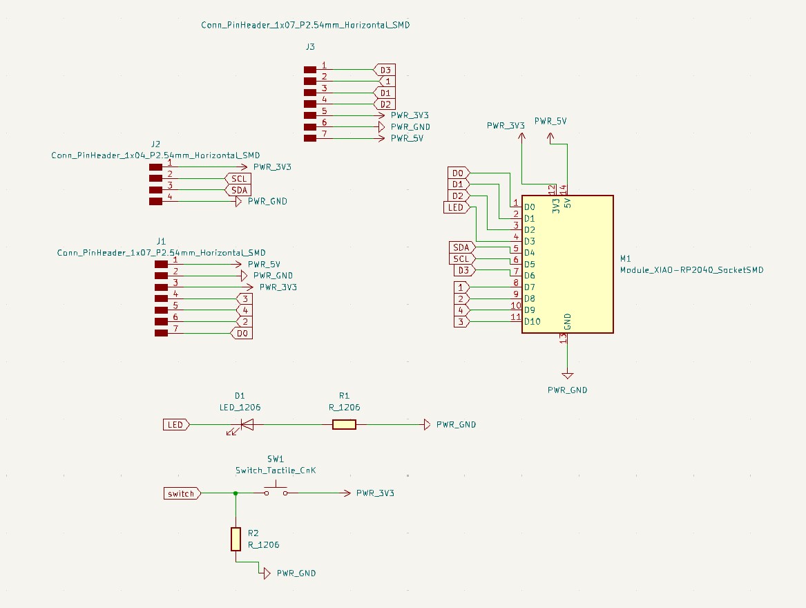
The design of my two boards is based on the development and improvement of my two previous boards.
The two boards created have generic connections at 3 points, I have added an LED and a switch to better complement the design of the same, so that they can be controlled by that means.
The initial design
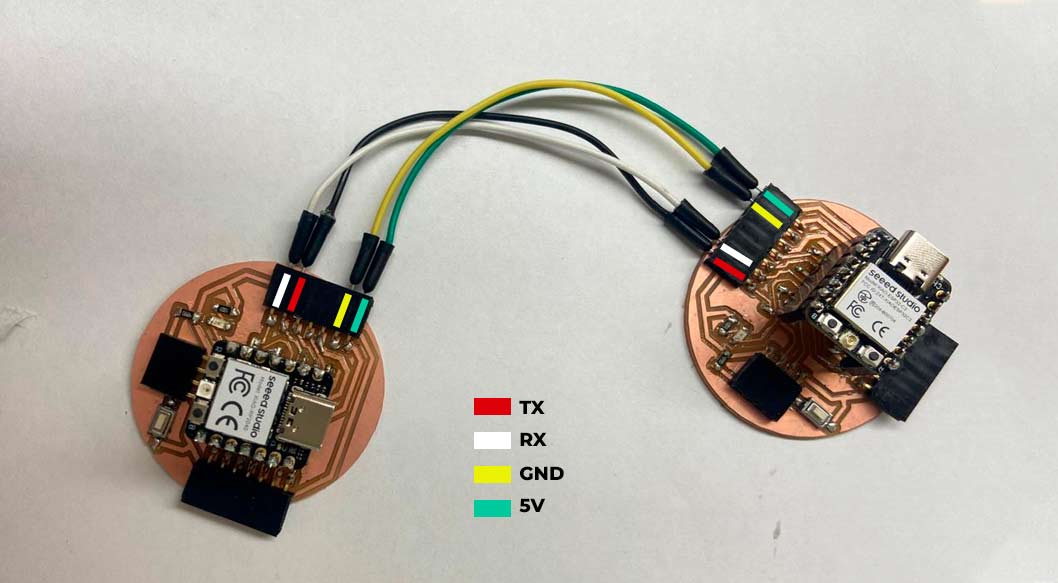
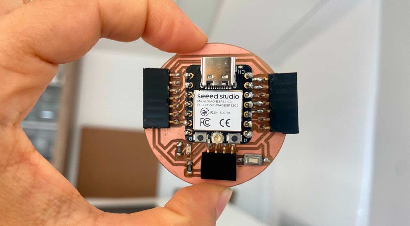
To develop the design, I based one of the boards on the Xiao ESP32-C3 and the other on the RP2040, so that both have UART communication through the TX and RX pins, but with a wired Jumper connection.
For this, I added to my previous work, a switch with its 4990ohm resistor and the connection of this to one of the pins, leaving the others free to be used with different Outputs.
BOM and Schematic for Maryo-Esp
Maryo-Esp |
Where to buy? | Amount |
| Seeed Studio XIAO RP2040 | Seeed Studio | 1 |
| 1kΩ resistor | Digikey | 4 |
| LED | Digikey | 4 |
| Male 4 row vertical header | Digikey | 1 |
Maryo-RP |
Where to buy? | Amount |
| Seeed Studio XIAO RP2040 | Seeed Studio | 1 |
| 1kΩ resistor | Digikey | 4 |
| LED | Digikey | 4 |
| Male 4 row vertical header | Digikey | 1 |
Soldering and programming tests with Output
For this case, I first arranged all my components to start soldering, such as: soldering iron, resistors, LEDs, Header connectors, Xiao and Flux.
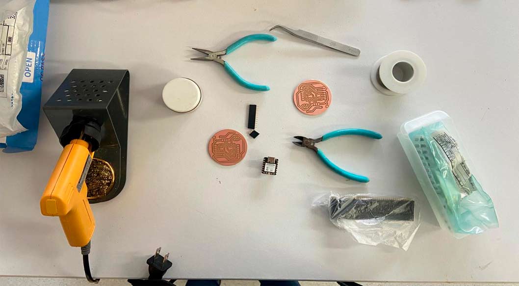
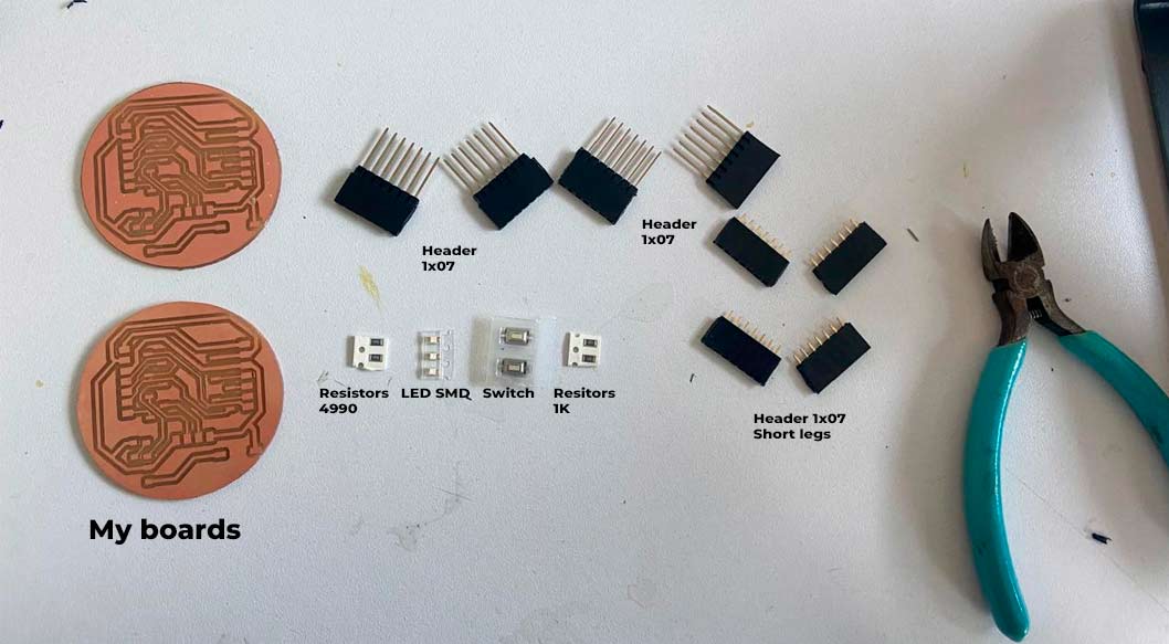
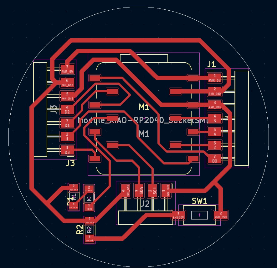
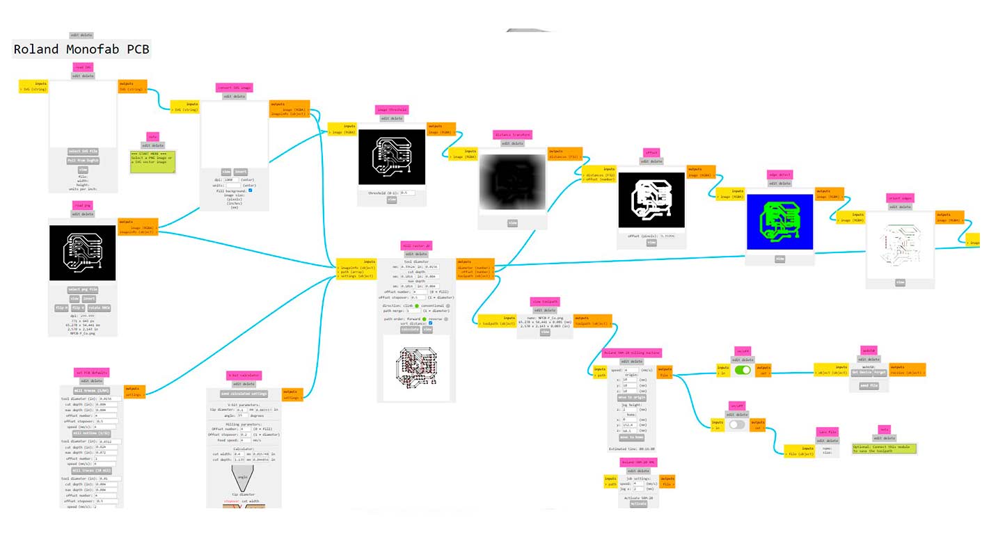
Plate milling
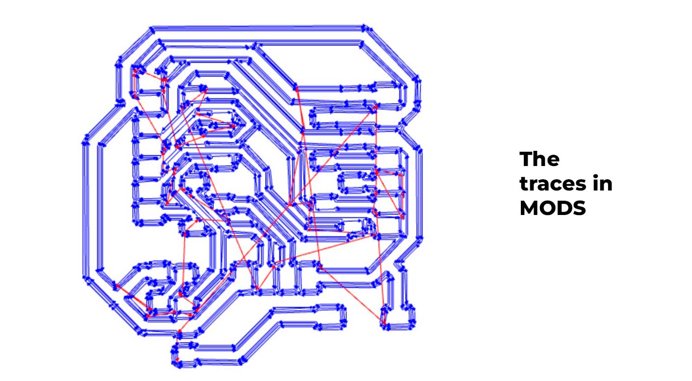
To get here, I passed my PNGs to the MODS program, I attach a photo of my traces to export and send to milling.
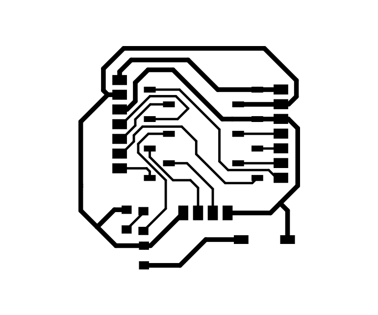

From here I transferred the PNGs to MODS to get the traces, SML files and some background settings to achieve the cut of my board.
Here is the SML file and some videos of the process! everything went correctly, remember that there are two plates that we milled and soldered.
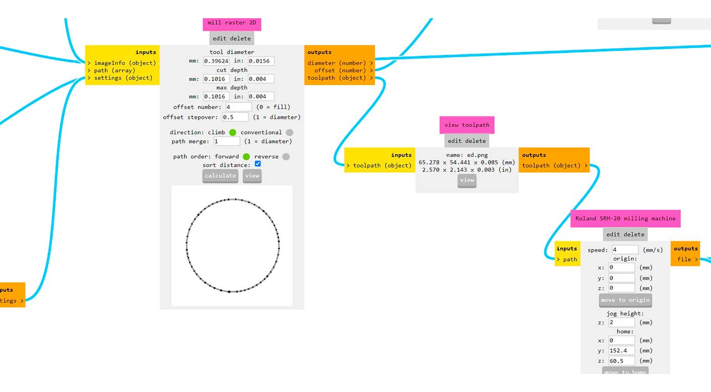
Here is the root of the total configuration
I leave you the download link of my SML files so you can mill it if you wish!
From here the milling process:
Here is the result of the milling of my boards
Component soldering
To make the soldering of the board, I used the soldering iron and tin, little by little I was accommodating the components
- I used the soldering iron at 310°C and Flux on the board and the component.
Something that helped me to solder faster my two boards was to prepare the components and solder at the same time, the first resistor of board 1 and the same on board 2, so that I was advancing in an accelerated way and finishing on time.
Codification
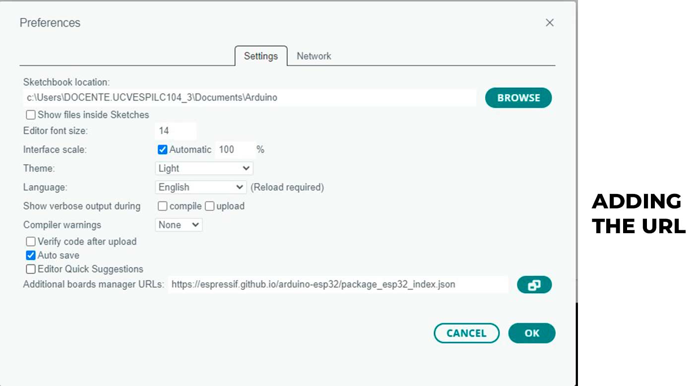
Something important to consider is the installation of the Xiao ESP32-C3 library from the ARDUINO.IDE library, consider that it is also important to add in preferences the link of the RAW:
https://raw.githubusercontent.com/espressif/arduino-esp32/gh-pages/package_esp32_dev_index.json
Before I started, I had some doubts about the Xiao ESP32-C3, as I had not programmed one of these before, so to start with I used my NODO board and connected a Servo motor to make it work with its programming, I leave you my test here:
Servo Motor
For this other case I made the coding of a Servo motor with my board with the ESPC3-C3.
           const int servoPin = D2;  // Pin D3 en la Xiao ESP32C3
   unsigned long tiempoInicio;  // Variable para guardar el tiempo de inicio del pulso
   int angulo = 0;  // Ángulo inicial del servo

   void setup() {
     pinMode(servoPin, OUTPUT);  // Configurar el pin del servo como salida
   }

   void loop() {
     // Mover el servo de 0 grados a 180 grados y viceversa
     for (angulo = 0; angulo <= 180; angulo++) {
       moverServo(angulo);  // Llamar a la función para mover el servo al ángulo deseado
       delay(15);  // Pequeña pausa para dar tiempo al servo a alcanzar la posición
     }

     delay(1000);  // Esperar un segundo en la posición final

     for (angulo = 180; angulo >= 0; angulo--) {
       moverServo(angulo);  // Llamar a la función para mover el servo al ángulo deseado
       delay(15);  // Pequeña pausa para dar tiempo al servo a alcanzar la posición
     }

     delay(1000);  // Esperar un segundo en la posición inicial
   }

   void moverServo(int angulo) {
     // Calcular el ancho del pulso PWM necesario para el ángulo dado (entre 0 y 180 grados)
     int anchoPulso = map(angulo, 0, 180, 500, 2400);  // Mapear ángulo a duración del pulso en microsegundos

     // Generar el pulso de control PWM durante el tiempo requerido para alcanzar el ángulo deseado
     digitalWrite(servoPin, HIGH);  // Establecer el pin en alto
     delayMicroseconds(anchoPulso);  // Mantener el pin en alto durante el ancho del pulso
     digitalWrite(servoPin, LOW);  // Establecer el pin en bajo
   }
Here is how it works!
I also continued testing with my NODO board to light up a LED, here is my test
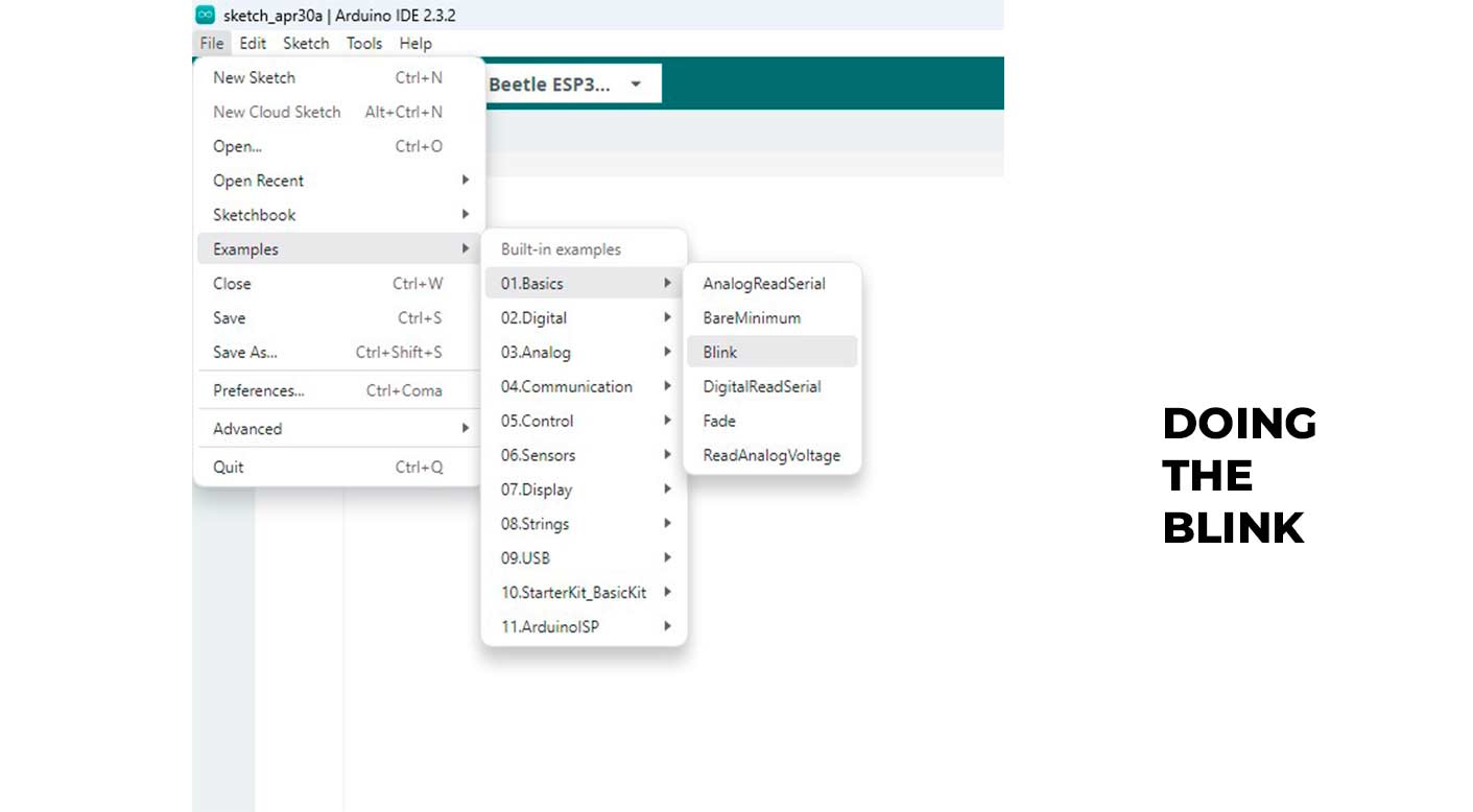
Blink
Starting with the code now, to verify that my board works, I used the basic ARDUINO.IDE code to get my LED on PIN D3 of the Xiao ESP32-C3 to light up, here the code and the result.
        /*
  Blink

  Turns an LED on for one second, then off for one second, repeatedly.

  Most Arduinos have an on-board LED you can control. On the UNO, MEGA and ZERO
  it is attached to digital pin 13, on MKR1000 on pin 6. LED_BUILTIN is set to
  the correct LED pin independent of which board is used.
  If you want to know what pin the on-board LED is connected to on your Arduino
  model, check the Technical Specs of your board at:
  https://www.arduino.cc/en/Main/Products

  modified 8 May 2014
  by Scott Fitzgerald
  modified 2 Sep 2016
  by Arturo Guadalupi
  modified 8 Sep 2016
  by Colby Newman

  This example code is in the public domain.

  https://www.arduino.cc/en/Tutorial/BuiltInExamples/Blink
*/

// the setup function runs once when you press reset or power the board
void setup() {
  // initialize digital pin LED_BUILTIN as an output.
  pinMode(D3, OUTPUT);
}

// the loop function runs over and over again forever
void loop() {
  digitalWrite(D3, HIGH);  // turn the LED on (HIGH is the voltage level)
  delay(1000);                      // wait for a second
  digitalWrite(D3, LOW);   // turn the LED off by making the voltage LOW
  delay(1000);                      // wait for a second
}
/*
  Blink

  Turns an LED on for one second, then off for one second, repeatedly.

  Most Arduinos have an on-board LED you can control. On the UNO, MEGA and ZERO
  it is attached to digital pin 13, on MKR1000 on pin 6. LED_BUILTIN is set to
  the correct LED pin independent of which board is used.
  If you want to know what pin the on-board LED is connected to on your Arduino
  model, check the Technical Specs of your board at:
  https://www.arduino.cc/en/Main/Products

  modified 8 May 2014
  by Scott Fitzgerald
  modified 2 Sep 2016
  by Arturo Guadalupi
  modified 8 Sep 2016
  by Colby Newman

  This example code is in the public domain.

  https://www.arduino.cc/en/Tutorial/BuiltInExamples/Blink
*/

// the setup function runs once when you press reset or power the board
void setup() {
  // initialize digital pin LED_BUILTIN as an output.
  pinMode(D3, OUTPUT);
}

// the loop function runs over and over again forever
void loop() {
  digitalWrite(D3, HIGH);  // turn the LED on (HIGH is the voltage level)
  delay(1000);                      // wait for a second
  digitalWrite(D3, LOW);   // turn the LED off by making the voltage LOW
  delay(1000);                      // wait for a second
}
The test with the board and the ESP32
The same test but with the XIAO RP2040
THE FIRST TEST
Ultrasonic Sensor with Neopixel
To make the connection between the two boards, I called one of them MASTER (the one with the RP2040) and the other NODO (the one with the ESP32-C3), so that the Master takes the signal and sends it in response to the NODO to activate the OUTPUT.
For this step as first example I am using in the MASTER the ultrasonic sensor and in the NODE the Neopixel as response of the received signal.
Remember that my two boards are connected by RX and TX cable, so it will always appear in the programming code in the #include /Wire.h/ section.
I show you the code to make only the Sensor work in my MASTER, remember that here it is only to verify the operation, I don't relate it with the NODO board yet.
        #define TRIG_PIN 10  // Pin TRIG conectado al pin D10 en la Xiao ESP32-C3
#define ECHO_PIN 19  // Pin ECHO conectado al pin D19 en la Xiao ESP32-C3

void setup() {
  Serial.begin(9600);  // Iniciar comunicación serial para mostrar resultados en el monitor serial
  pinMode(TRIG_PIN, OUTPUT);  // Configurar el pin TRIG como salida
  pinMode(ECHO_PIN, INPUT);   // Configurar el pin ECHO como entrada
}

void loop() {
  long duration;
  float distance_cm;

  // Generar un pulso corto en el pin TRIG para activar el sensor ultrasónico
  digitalWrite(TRIG_PIN, LOW);
  delayMicroseconds(2);
  digitalWrite(TRIG_PIN, HIGH);
  delayMicroseconds(10);
  digitalWrite(TRIG_PIN, LOW);

  // Medir el tiempo que tarda en llegar el eco (en microsegundos)
  duration = pulseIn(ECHO_PIN, HIGH);

  // Calcular la distancia en centímetros utilizando la fórmula de conversión
  distance_cm = duration * 0.034 / 2;  // La velocidad del sonido es 340 m/s (0.034 cm/microsegundo)

  // Mostrar la distancia medida en el monitor serial
  Serial.print("Distancia: ");
  Serial.print(distance_cm);
  Serial.println(" cm");

  delay(1000);  // Esperar un segundo antes de realizar la próxima lectura
}
ONLY SENSOR MASTER.INO
Here is a video showing how it works!
Neopixel
Here with the Neopixel the intention was to test the code, first time that I made the coding and it worked, I helped myself with the documentation of Adrian Torres.
        #include /Adafruit_NeoPixel.h/

            #define PIN_NEOPIXEL 3  // Pin D3 en la Xiao ESP32-C3
            #define NUM_PIXELS 8    // Número de LEDs en tu tira Neopixel

            Adafruit_NeoPixel strip = Adafruit_NeoPixel(NUM_PIXELS, PIN_NEOPIXEL, NEO_GRB + NEO_KHZ800);

            void setup() {
              strip.begin();  // Inicializar la tira Neopixel
              strip.show();   // Apagar todos los LEDs al inicio
            }

            void loop() {
              // Cambiar el color de los LEDs gradualmente
              for (int i = 0; i < NUM_PIXELS; i++) {
                // Establecer el color de cada LED (rojo, verde, azul)
                strip.setPixelColor(i, 255, 0, 0);  // Rojo
                strip.show();  // Mostrar el color en el LED
                delay(50);     // Pequeña pausa
              }

              delay(1000);  // Esperar un segundo

              for (int i = 0; i < NUM_PIXELS; i++) {
                strip.setPixelColor(i, 0, 255, 0);  // Verde
                strip.show();
                delay(50);
              }

              delay(1000);  // Esperar un segundo

              for (int i = 0; i < NUM_PIXELS; i++) {
                strip.setPixelColor(i, 0, 0, 255);  // Azul
                strip.show();
                delay(50);
              }

              delay(1000);  // Esperar un segundo
            }
ONLY NEOPIXEL NODO.INO
Here we link the two codes and their connection to each other for the operation of the complete circuit using RX and TX.
Code to operate the MASTER and the sensor:
      #include

        #define TRIGGER_PIN 9    // Pin del trigger del sensor ultrasónico
        #define ECHO_PIN 10      // Pin del echo del sensor ultrasónico
        #define SERIAL_BAUD_RATE 9600  // Velocidad de comunicación serial

        long duration;
        int distance;

        void setup() {
          Serial.begin(SERIAL_BAUD_RATE);  // Inicia la comunicación serial
          pinMode(TRIGGER_PIN, OUTPUT);    // Configura el pin del trigger como salida
          pinMode(ECHO_PIN, INPUT);        // Configura el pin del echo como entrada
        }

        void loop() {
          // Enviar pulso ultrasónico
          digitalWrite(TRIGGER_PIN, LOW);
          delayMicroseconds(2);
          digitalWrite(TRIGGER_PIN, HIGH);
          delayMicroseconds(10);
          digitalWrite(TRIGGER_PIN, LOW);

          // Leer el tiempo de duración del pulso
          duration = pulseIn(ECHO_PIN, HIGH);

          // Calcular la distancia
          distance = duration * 0.034 / 2;

          // Enviar comandos al nodo basado en la distancia
          if (distance < 20) {  // Si la distancia es menor a 20 cm
            Serial.write(1);    // Enviar señal para encender el NeoPixel
          } else {
            Serial.write(0);    // Enviar señal para apagar el NeoPixel
          }

          delay(500);  // Espera 500 ms antes de la próxima lectura
        }
MASTER SENSOR CODE.INO
I'll explain a bit of the code:
Ultrasonic sensor configuration: The ultrasonic sensor pins are configured.
Distance reading: The code sends a pulse and measures the return time to calculate the distance.
Sending commands: Depending on the measured distance, a serial command is sent (1 to turn the NeoPixel on, 0 to turn it off).
Including Libraries and Defining Pins:
      #include Arduino.h>

        #define TRIGGER_PIN 9    // Pin del trigger del sensor ultrasónico
        #define ECHO_PIN 10      // Pin del echo del sensor ultrasónico
        #define SERIAL_BAUD_RATE 9600  // Velocidad de comunicación serial
• Arduino.h: Includes the basic Arduino functions.
• Defines the pin to which the trigger pin of the ultrasonic sensor is connected.
• ECHO_PIN: Defines the pin to which the echo pin of the ultrasonic sensor is connected.
• SERIAL_BAUD_RATE: Defines the serial communication speed (9600 bits per second).
Initial Configuration
      void setup() {
        Serial.begin(SERIAL_BAUD_RATE);  // Inicia la comunicación serial
        pinMode(TRIGGER_PIN, OUTPUT);    // Configura el pin del trigger como salida
        pinMode(ECHO_PIN, INPUT);        // Configura el pin del echo como entrada
      }
• Serial.begin(SERIAL_BAUD_RATE): Initialises serial communication at 9600 bps.
• pinMode(TRIGGER_PIN, OUTPUT): Configures the trigger pin as output.
• pinMode(ECHO_PIN, INPUT): Configures the echo pin as input.
Main Loop
      void loop() {
        // Enviar pulso ultrasónico
        digitalWrite(TRIGGER_PIN, LOW);
        delayMicroseconds(2);
        digitalWrite(TRIGGER_PIN, HIGH);
        delayMicroseconds(10);
        digitalWrite(TRIGGER_PIN, LOW);

        // Leer el tiempo de duración del pulso
        long duration = pulseIn(ECHO_PIN, HIGH);

        // Calcular la distancia
        int distance = duration * 0.034 / 2;

        // Enviar comandos al nodo basado en la distancia
        if (distance < 20) {  // Si la distancia es menor a 20 cm
          Serial.write(1);    // Enviar señal para encender el NeoPixel
        } else {
          Serial.write(0);    // Enviar señal para apagar el NeoPixel
        }

        delay(500);  // Espera 500 ms antes de la próxima lectura
      }
Send ultrasonic pulse:
• DigitalWrite(TRIGGER_PIN, LOW): Sets the trigger pin low.
• delayMicroseconds(2): Wait 2 microseconds.
• digitalWrite(TRIGGER_PIN, HIGH): Set trigger pin high.
• delayMicroseconds(10): Waits 10 microseconds.
• digitalWrite(TRIGGER_PIN, LOW): Sets the trigger pin low.
Read the pulse duration time:
• pulseIn(ECHO_PIN, HIGH): measure the time the echo pin stays high.
Calculate the distance:
• distance = duration * 0.034 / 2: Calculate the distance in centimetres.
Send commands to the node:
• Serial.write(1): If the distance is less than 20 cm, send a command 1 to turn on the NeoPixel.
• Serial.write(0): If the distance is greater than or equal to 20 cm, send a 0 command to turn off the NeoPixel.
• delay(500): Wait 500 ms before the next reading.
Code to operate the NODE and the NEOPIXEL:
      #include
        #include

        #define NEOPIXEL_PIN 6    // Pin al que está conectado el NeoPixel
        #define NUM_PIXELS 1      // Número de píxeles NeoPixel
        #define SERIAL_BAUD_RATE 9600  // Velocidad de comunicación serial

        Adafruit_NeoPixel strip = Adafruit_NeoPixel(NUM_PIXELS, NEOPIXEL_PIN, NEO_GRB + NEO_KHZ800);

        void setup() {
          Serial.begin(SERIAL_BAUD_RATE);  // Inicia la comunicación serial
          strip.begin();                   // Inicializa la librería NeoPixel
          strip.show();                    // Inicializa todos los píxeles apagados
        }

        void loop() {
          if (Serial.available() > 0) {
            int command = Serial.read();  // Lee el comando de la placa maestra

            if (command == 1) {
              // Enciende el NeoPixel
              strip.setPixelColor(0, strip.Color(255, 0, 0));  // Rojo, por ejemplo
              strip.show();
            } else if (command == 0) {
              // Apaga el NeoPixel
              strip.setPixelColor(0, strip.Color(0, 0, 0));  // Apaga el píxel
              strip.show();
            }
          }
        }
NODE NEOPIXEL CODE.INO
Including Libraries and Defining Pins :
      #include Arduino.h
        #include Adafruit_NeoPixel.h

        #define NEOPIXEL_PIN 6    // Pin al que está conectado el NeoPixel
        #define NUM_PIXELS 1      // Número de píxeles NeoPixel
        #define SERIAL_BAUD_RATE 9600  // Velocidad de comunicación serial

        Adafruit_NeoPixel strip = Adafruit_NeoPixel(NUM_PIXELS, NEOPIXEL_PIN, NEO_GRB + NEO_KHZ800);
• Arduino.h: Includes the basic Arduino functions.
• Adafruit_NeoPixel.h: Includes the functions to control NeoPixels.
• NEOPIXEL_PIN: Defines the pin to which the NeoPixel is connected.
• NUM_PIXELS: Defines the number of NeoPixel pixels.
• SERIAL_BAUD_RATE: Defines the serial communication speed (9600 bits per second).
• strip: Creates an Adafruit_NeoPixel object to control the pixels.
Initial Configuration:
      void setup() {
        Serial.begin(SERIAL_BAUD_RATE);  // Inicia la comunicación serial
        strip.begin();                   // Inicializa la librería NeoPixel
        strip.show();                    // Inicializa todos los píxeles apagados
      }
• Serial.begin(SERIAL_BAUD_RATE): Initializes serial communication at 9600 bps.
• strip.begin(): Initializes the NeoPixel library.
• strip.show(): Turns off all pixels at startup.
Main Loop:
      void loop() {
        if (Serial.available() > 0) {
          int command = Serial.read();  // Lee el comando de la placa maestra

          if (command == 1) {
            // Enciende el NeoPixel
            strip.setPixelColor(0, strip.Color(255, 0, 0));  // Rojo, por ejemplo
            strip.show();
          } else if (command == 0) {
            // Apaga el NeoPixel
            strip.setPixelColor(0, strip.Color(0, 0, 0));  // Apaga el píxel
            strip.show();
          }
        }
      }
Check if data is available on the serial port:
• Serial.available() > 0: Check if data is available to read.
Read command from the master board:
• int command = Serial.read(): Reads the command sent by the master board.
Turn the NeoPixel on or off based on the command:
• command == 1: If command is 1, turn on the NeoPixel.
• strip.setPixelColor(0, strip.Color(255, 0, 0, 0)): Sets the colour of the first pixel to red.
• strip.show(): Updates the NeoPixel to show the configured colour.
• command == 0: If command is 0, turns off the NeoPixel.
• strip.setPixelColor(0, strip.Color(0, 0, 0, 0)): Sets the colour of the first pixel to black (off).
• strip.show(): Updates the NeoPixel to show the set colour (off).
With all this explanation, I will now load the programme and show how it works.
Here is the result!
PARTICULAR COMMUNICATION: Communication between my boards
For communication between the two boards using the TX and RX pins, I made sure that both codes are using the corresponding serial ports. In the case of the XIAO RP2040 and XIAO ESP32-C3, "Serial 1" is used for the additional TX and RX pins (not the USB port which is Serial).
Code for Master Board (XIAO RP2040)
Serial 1 is used here for serial communication on the TX and RX pins. The TX pin of the RP2040 must be connected to the RX pin of the ESP32-C3, and the RX pin of the RP2040 must be connected to the TX pin of the ESP32-C3.
What do I want to connect?
What I want to connect are my two boards using the UART connection through the TX and RX pins between an RP2040 and an ESP32-C3, so I leave again the image of the two boards and their more detailed connections.
Connections Summary
XIAO RP2040:
TX (Serial1) → RX of XIAO ESP32-C3
RX (Serial1) → TX of XIAO ESP32-C3
XIAO ESP32-C3:
TX (Serial1) → RX of XIAO RP2040
RX (Serial1) → TX of XIAO RP2040
Does it work?
I use the same ultrasonic sensor to turn on the Neopixel, in the same way at a distance less than 10cm.
Here I leave a video of its operation and the link to the ARDUINO.IDE file for programming.
Also I made another example, the intention is to use the ultrasonic sensor to run the motor, when the first one is less than 10cm away, it will automatically turn on the servo.
Here I leave a video of its operation and the links to the ARDUINO.IDE file for programming.
CONNECTION BY INDEPENDENT BOARD IDENTIFIER
To make the identification of each board as independent and they can communicate with each other by unique addresses, I pass you the modified codes with their identification addresses between the MASTER and the NODE and also the video of the operation of them with their respective outputs.
The MASTER board has an identifier with the number 1, while the NODO has an identifier with the number 2.
Code for the Master
        #define TRIGGER_PIN 3
#define ECHO_PIN 4
#define BAUD_RATE 9600  // Tasa de baudios para la comunicación serial
#define MASTER_ID 1     // Identificador de la placa master
#define NODE_ID 2       // Identificador del nodo

void setup() {
  Serial.begin(BAUD_RATE); // Inicia la comunicación serial a 9600 baudios
  pinMode(TRIGGER_PIN, OUTPUT);
  pinMode(ECHO_PIN, INPUT);
  Serial.println("Setup completo");
}

void loop() {
  // Enviar pulso ultrasónico
  digitalWrite(TRIGGER_PIN, LOW);
  delayMicroseconds(2);
  digitalWrite(TRIGGER_PIN, HIGH);
  delayMicroseconds(10);
  digitalWrite(TRIGGER_PIN, LOW);

  // Leer el tiempo de duración del pulso
  long duration = pulseIn(ECHO_PIN, HIGH);

  // Calcular la distancia en cm
  int distance = duration * 0.034 / 2;

  // Enviar la distancia al monitor serial
  Serial.print("Distancia: ");
  Serial.print(distance);
  Serial.println(" cm");

  // Enviar señal al nodo si la distancia es menor a 20 cm
  Serial.print(MASTER_ID); // Identificador del master
  Serial.print(",");
  Serial.print(NODE_ID);   // Identificador del nodo
  Serial.print(",");
  if (distance < 20) {
    Serial.print(1);      // Envía 1 si la distancia es menor a 20 cm
  } else {
    Serial.print(0);      // Envía 0 si la distancia es mayor o igual a 20 cm
  }
  Serial.println();       // Enviar un salto de línea para marcar el final del mensaje

  delay(500);
}
Definitions and Constants:
• #define TRIGGER_PIN 3 and #define ECHO_PIN 4: These define the pins used for the ultrasonic sensor's trigger and echo.
• #define BAUD_RATE 9600: Sets the baud rate for serial communication to 9600.
• #define MASTER_ID 1 and #define NODE_ID 2: These define unique identifiers for the master board and node.
Setup Function:
• Serial.begin(BAUD_RATE): Initializes serial communication at 9600 baud.
• pinMode(TRIGGER_PIN, OUTPUT): Sets the trigger pin as an output.
• pinMode(ECHO_PIN, INPUT): Sets the echo pin as an input.
• Serial.println("Setup complete"): Prints a message indicating the setup is complete.
Loop Function:
Sending Ultrasonic Pulse
• digitalWrite(TRIGGER_PIN, LOW): Sets the trigger pin low.
• delayMicroseconds(2): Waits for 2 microseconds.
• digitalWrite(TRIGGER_PIN, HIGH): Sets the trigger pin high.
• delayMicroseconds(10): Waits for 10 microseconds.
• digitalWrite(TRIGGER_PIN, LOW): Sets the trigger pin low.
Reading Pulse Duration
• long duration = pulseIn(ECHO_PIN, HIGH): Reads the duration of the echo pin being high.
Calculating Distance:
• int distance = duration * 0.034 / 2: Converts the duration to distance in centimeters.
Sending Distance to Serial Monitor:
• Serial.print("Distance: "): Prints "Distance: ".
• Serial.print(distance): Prints the calculated distance.
• Serial.println(" cm"): Prints " cm".
Sending Signal to Node:
• Serial.print(MASTER_ID): Prints the master ID.
• Serial.print(","): Prints a comma.
• Serial.print(NODE_ID): Prints the node ID.
• Serial.print(","): Prints a comma.
• if (distance < 20) { Serial.print(1); } else { Serial.print(0); }: Sends 1 if the distance is less than 20 cm, otherwise sends 0.
• Serial.println(): Prints a newline.
Delay:
• delay(500): Waits for 500 milliseconds before repeating the loop.
Code for the Nodo
#include#define NEOPIXEL_PIN 6 #define NUMPIXELS 1 #define BAUD_RATE 9600 // Tasa de baudios para la comunicación serial #define NODE_ID 2 // Identificador del nodo Adafruit_NeoPixel pixels(NUMPIXELS, NEOPIXEL_PIN, NEO_GRB + NEO_KHZ800); void setup() { Serial.begin(BAUD_RATE); // Inicia la comunicación serial a 9600 baudios pixels.begin(); Serial.println("Setup completo"); } void loop() { if (Serial.available()) { // Leer el identificador del master, del nodo y la señal int masterID = Serial.parseInt(); char comma = Serial.read(); // Leer la coma int nodeID = Serial.parseInt(); comma = Serial.read(); // Leer la coma int signal = Serial.parseInt(); Serial.print("ID del master recibido: "); Serial.println(masterID); // Imprime el ID del master para depuración Serial.print("ID del nodo recibido: "); Serial.println(nodeID); // Imprime el ID del nodo para depuración Serial.print("Señal recibida: "); Serial.println(signal); // Imprime la señal recibida para depuración if (nodeID == NODE_ID) { // Verifica que el identificador del nodo sea correcto if (signal == 1) { pixels.setPixelColor(0, pixels.Color(255, 0, 0)); // Enciende el neopixel en rojo } else { pixels.setPixelColor(0, pixels.Color(0, 0, 0)); // Apaga el neopixel } pixels.show(); } } }
Explanation
Libraries and Definitions:
• #include : Includes the Adafruit NeoPixel library.
• #define NEOPIXEL_PIN 6: Sets the pin connected to the NeoPixel.
• #define NUMPIXELS 1: Sets the number of NeoPixels.
• #define BAUD_RATE 9600: Sets the baud rate for serial communication.
• #define NODE_ID 2: Sets the node ID.
Setup Function:
• Serial.begin(BAUD_RATE): Initializes serial communication at 9600 baud.
• pixels.begin(): Initializes the NeoPixel.
• Serial.println("Setup complete"): Prints a setup complete message.
Loop Function:
• Checks if there is data available in the serial buffer.
• Reads the master ID, node ID, and signal from the serial input.
• Prints the received IDs and signal for debugging.
• Verifies if the received node ID matches the predefined NODE_ID.
• If the signal is 1, it turns the NeoPixel red; otherwise, it turns it off.
• pixels.show(): Updates the NeoPixel with the new color.
Here is a video of the operation of the boards, connected together, with their respective sensors in the case of the Master and the Neopixel for the Node.
What I learned:
About RX and TX connections:
TX (Transmit) is used to send data, RX (Receive) is used to receive data. The TX pin of one device is connected to the RX pin of another device, and vice versa. This allows for serial communication between the two devices.
Purpose: Board identifiers distinguish different devices on a shared communication network
Importance: Ensuring that messages are correctly routed and processed by the intended device.
About The ID:
In the Code: The MASTER_ID and NODE_ID are used to verify and direct messages to the correct node, avoiding conflicts and ensuring precise communication.
In summary, RX and TX are essential for serial communication, and board identifiers are crucial for managing and routing messages in a network of multiple devices.
HERE THE FILES .INO: