2D & 3D model
Computer Aided Design
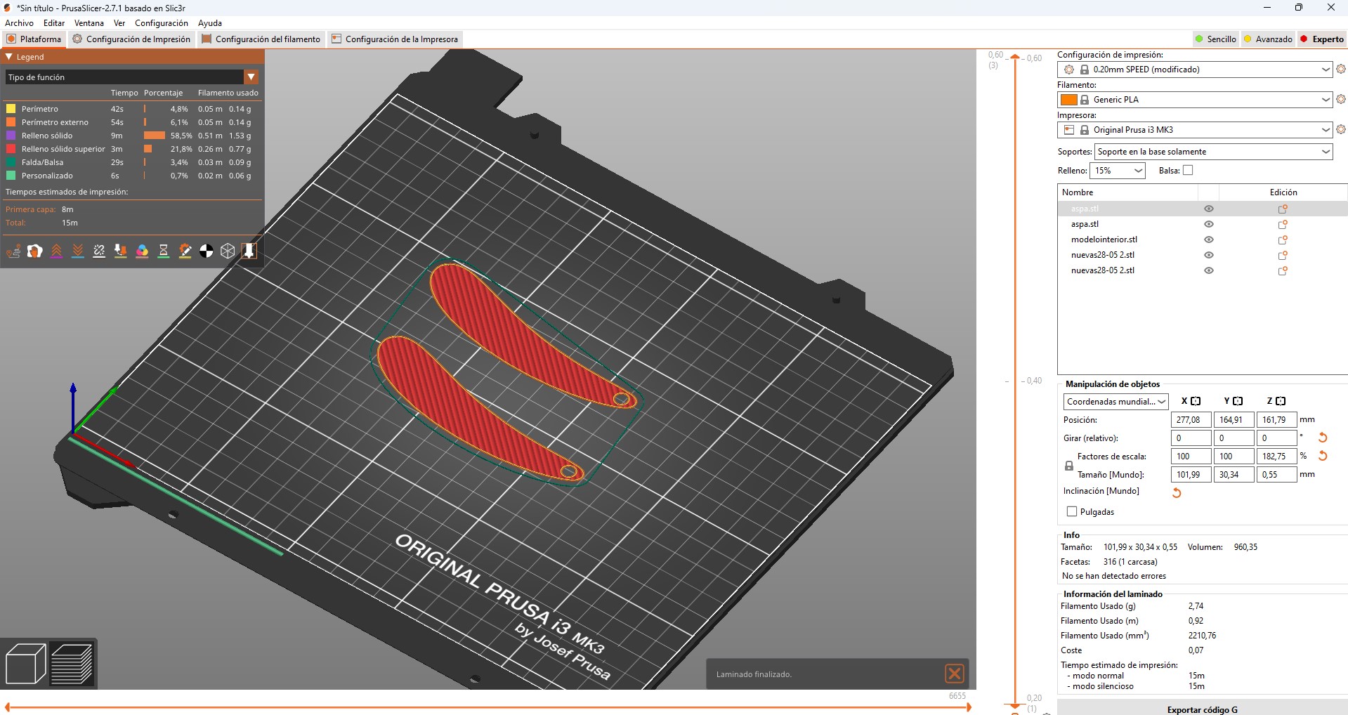
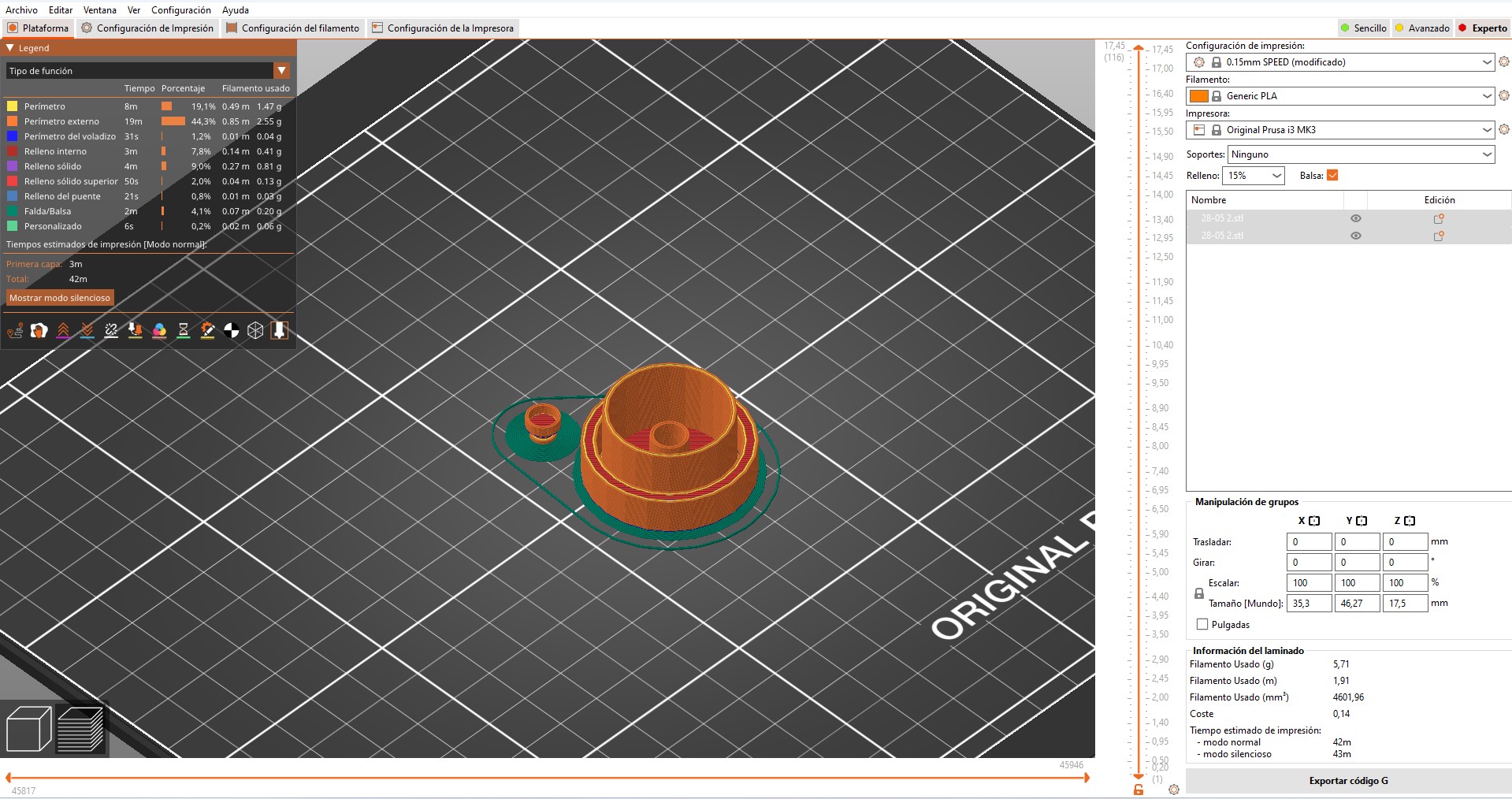
3D printing, laser cutting, mold?
Thanks to the change of my final project, I learned how to use fusion 360, it was hard work but finally I got a result quite close to what I didn't expect.
To explain a little about Fusion 360, we should consider that:
- It is very similar to Autocad with the 3D modeling function similar to Revit, to begin with, I leave you the download link of Fusion student version.
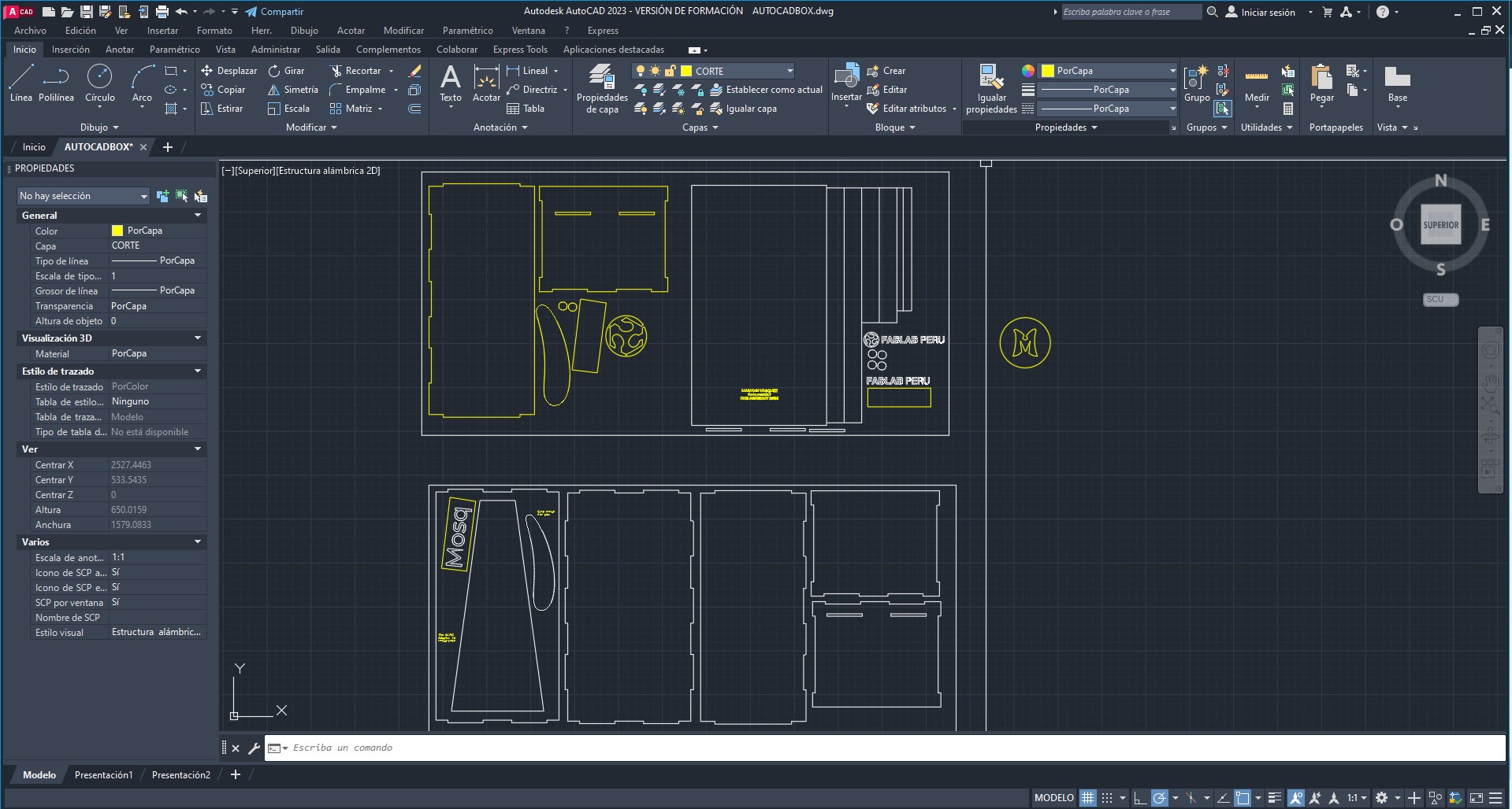
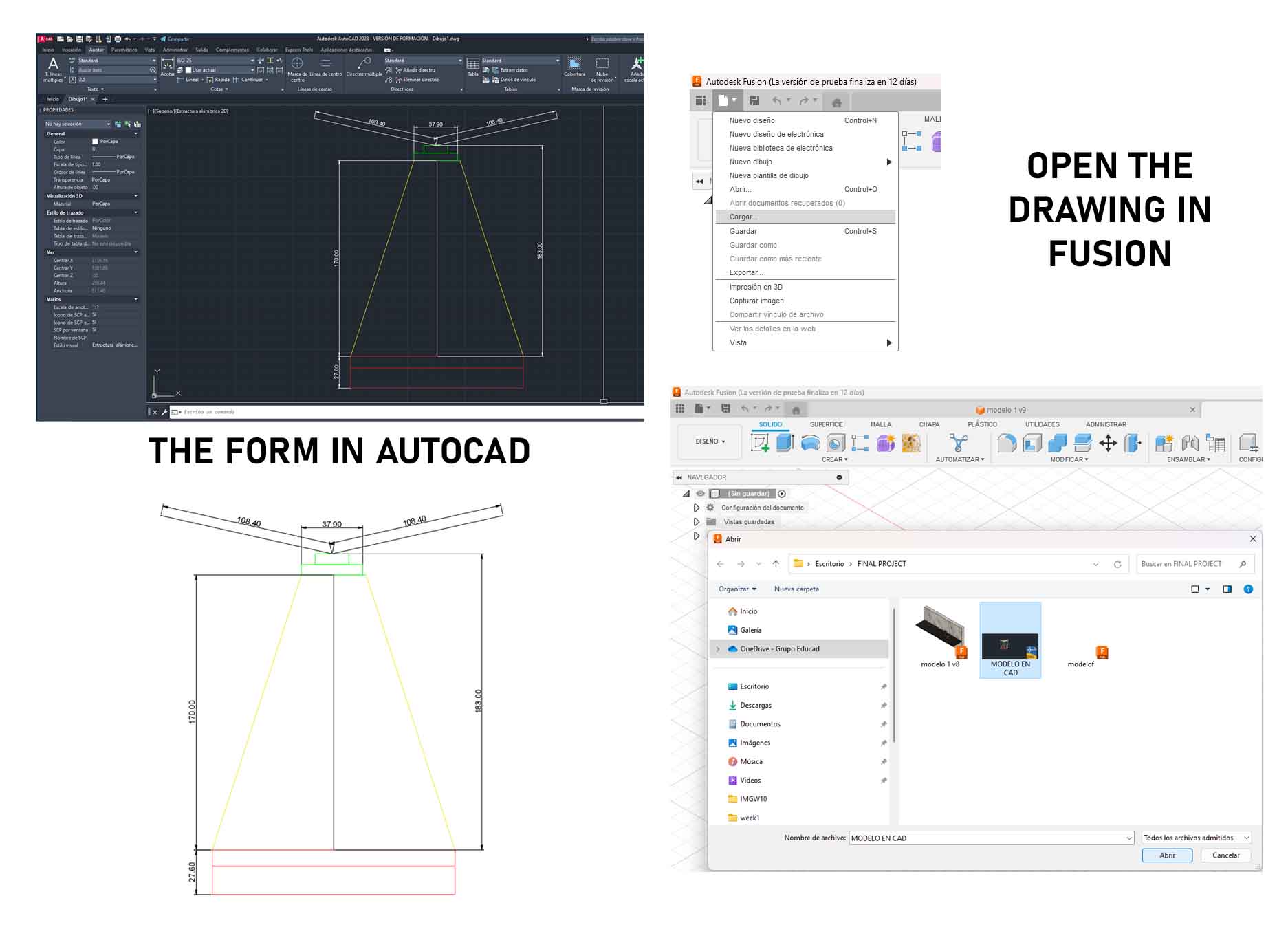
Link- I started by defining the measurements of my object using a sketch in Autocad 2D, and then taking into account the measures
The problem with voids and extrusions in modeling
Starting to discover modeling tools, I realized that I needed to make empty solid shapes for the main shape of my project.
I needed to leave the thickness at least 2mm, so I was trying to make a hole in the shape but it didn't work, I needed to make a copy of my main shape and scale it and then cut it, but how do I do it?
I started by making a copy of my shape, with the design of the two circles, the base of (15cm) and the top of (4cm) in copy and revolution, then I made the copy to the side and scaled it with the PUSH tool to be able to give it a distance less than what I have, considering its proportion to achieve the 2cm thickness of the walls of my object.
It was achieved, I select both and apply transform to give the CUT option, so that both shapes are subtracted, thus having my final shape
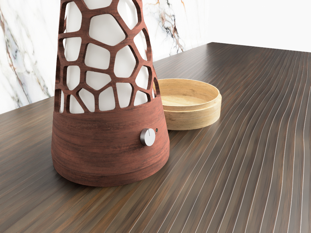
Voronoi and applications Part 1
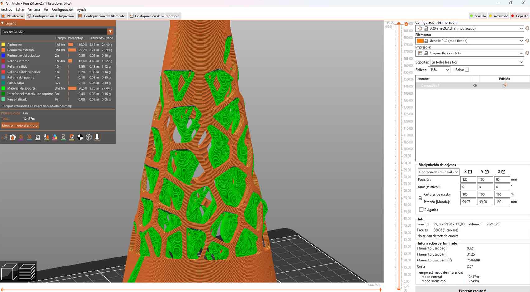
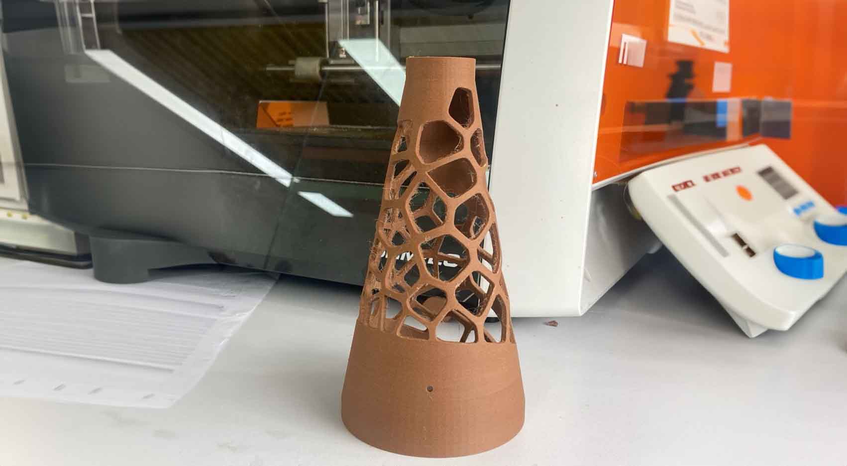
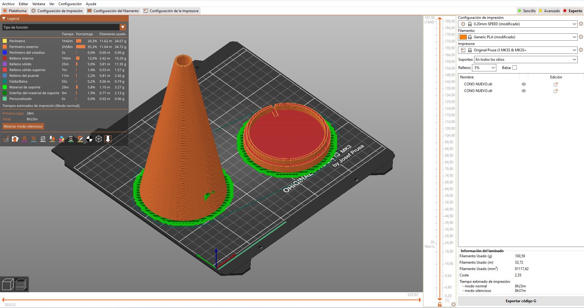
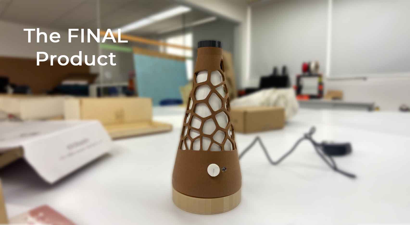
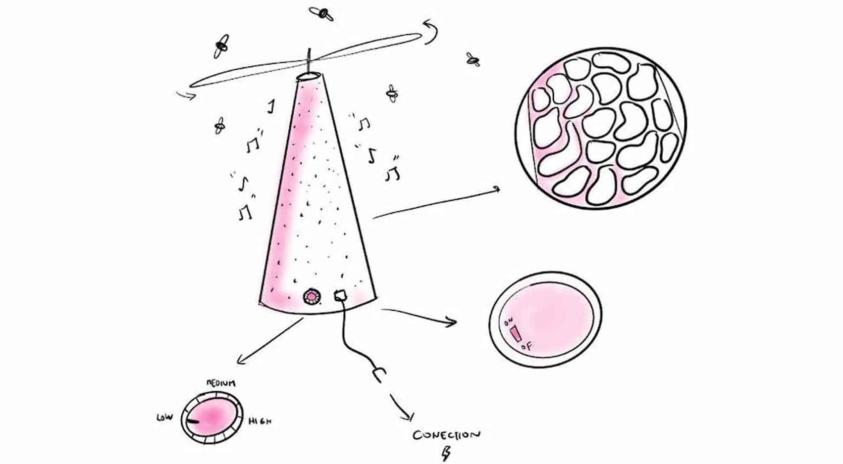
The design that I want to implement for the faces of my project is a pattern of organic shapes that are dispersed with fairly small separation margins, the intention is not to completely fill the model with the texture, nor to overload it visually.
To do this, I apply and download the Voronoi Sketch plugin, leave the LINK for the download and a TUTORIAL to see the installation and use procedure.
Link 1 Link 2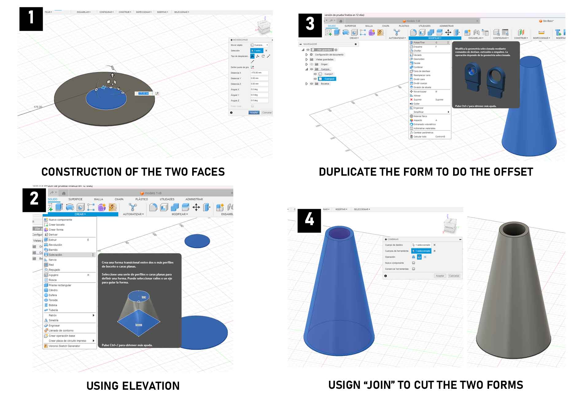
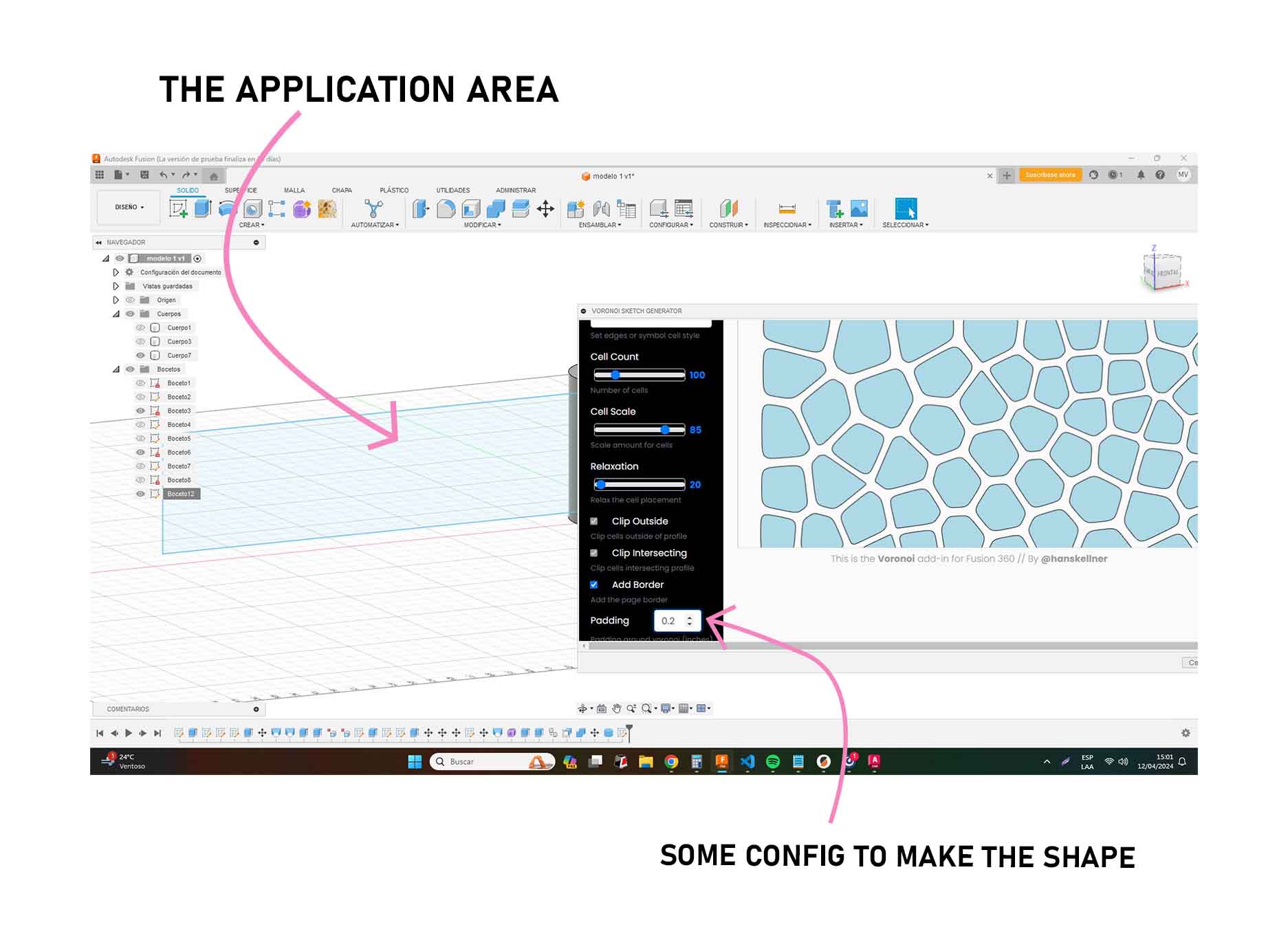
To begin, I make a rectangle or specific shape where the texture will be applied, always considering the exact area or perimeter for the plugin to read.
Voronoi and applications Part 2
After that, I select the plugin and click on the leaves icon, so that the application of the texture on the determined area is identified.
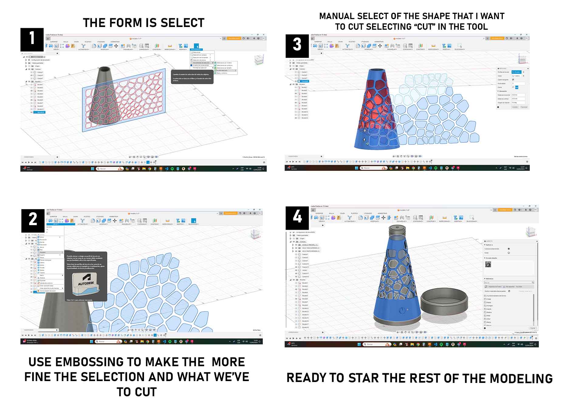
By doing this and accepting, another window will open to determine the shape of the pattern, the separation and the margin to be applied, I clicked "load to fusion 360" and that's it!
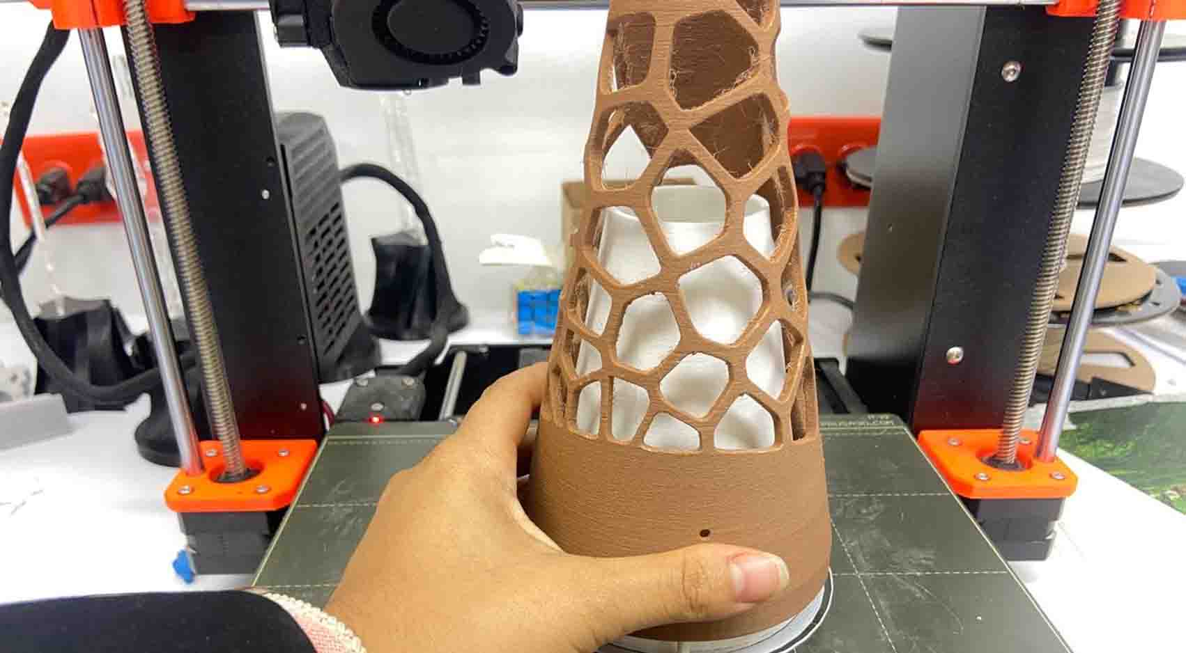
Once I have the texture, I must verify that it is in front of the cone, right in front, so that I can read the application, once I have the texture selected I will go to the "EMBOSSING" tool to apply the texture on the face that select precisely with my cursor, I can modify the application depth and the mode and then accept.
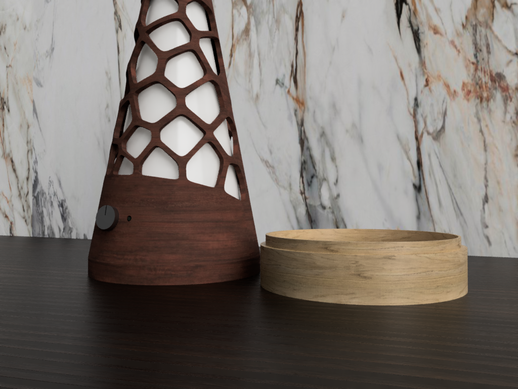
Continue with the modeling of more parts
We continue with the modeling of the base, the propellers, the cord, the threads and, above all, the most fun part, the application of the material.
From here follow the steps below:
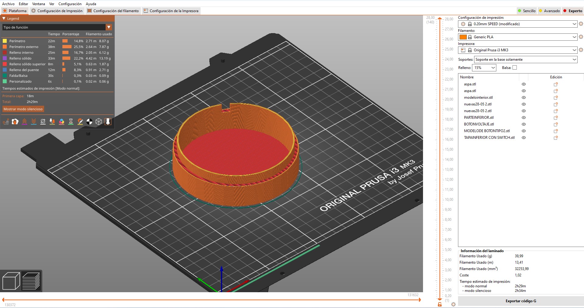
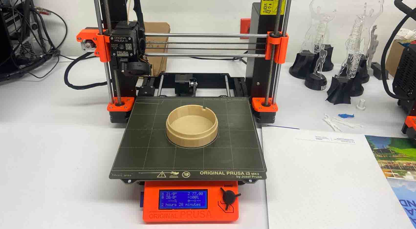
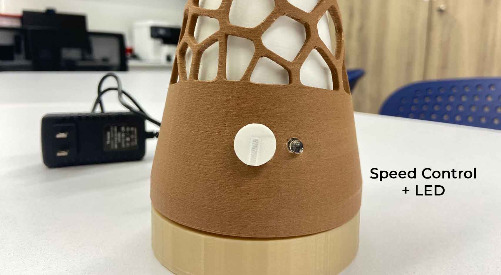
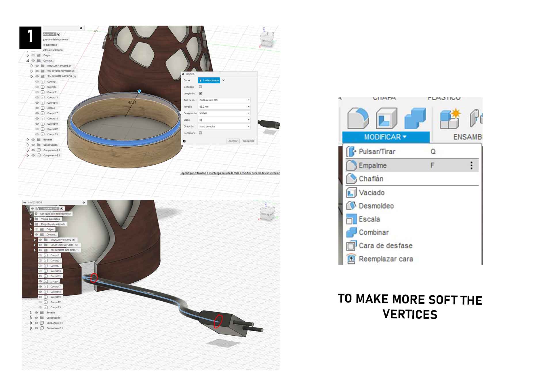
1. To make the modeling of the buttons, base I made it from the sketch of raised circles, relying on the SOLEVATION tool.
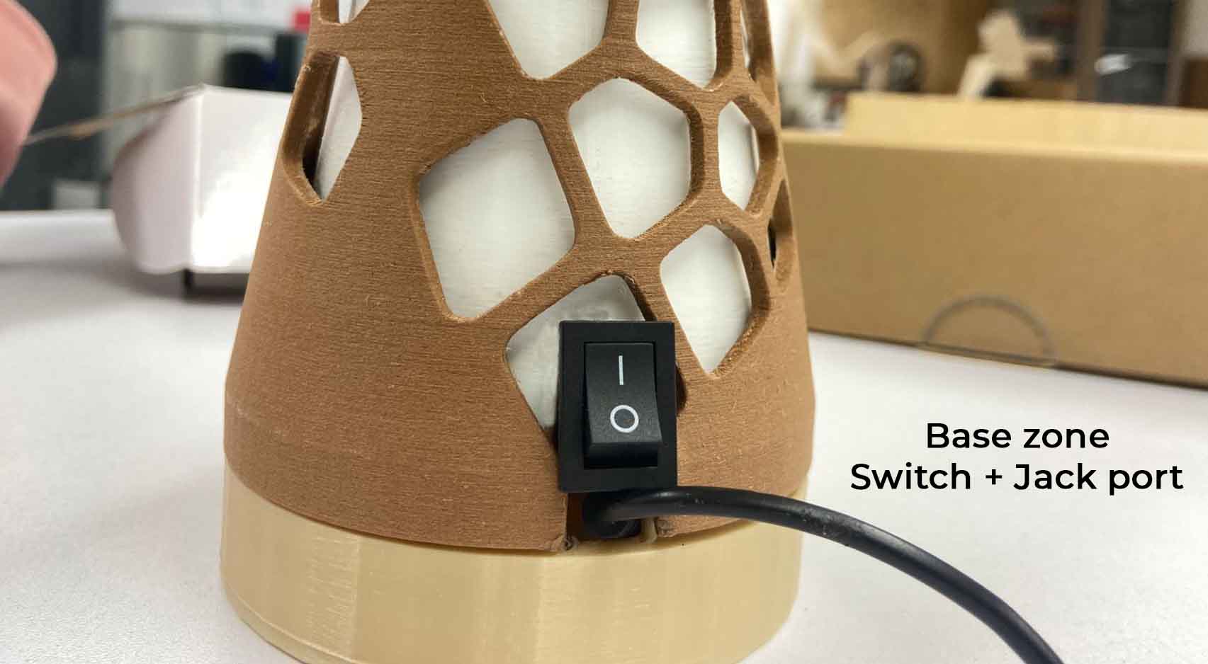
2. Starting with the sketch for the base, I made the circle in extrusion and applied the thread in the upper part, considering to make it with a metric ISO profile type, size 95mm with M95x6 thread designation and right hand opening, having the following result.
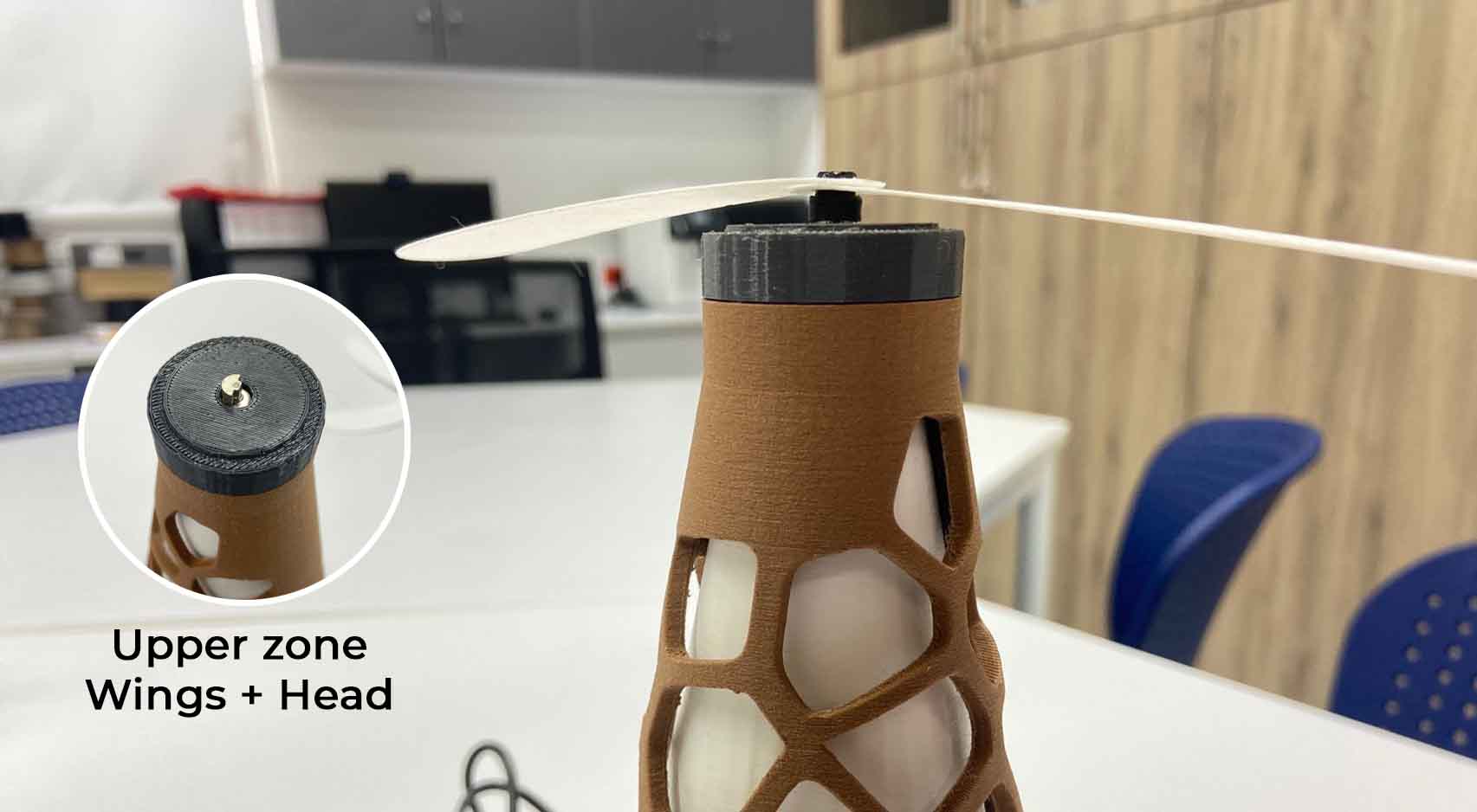
3.For the bead and the head I made it through the PIPE tool, defining the diameter of the bead and through extrusions the shape of the head, to give it a curvature I used EMPALME, to give more smoothness to the shape.
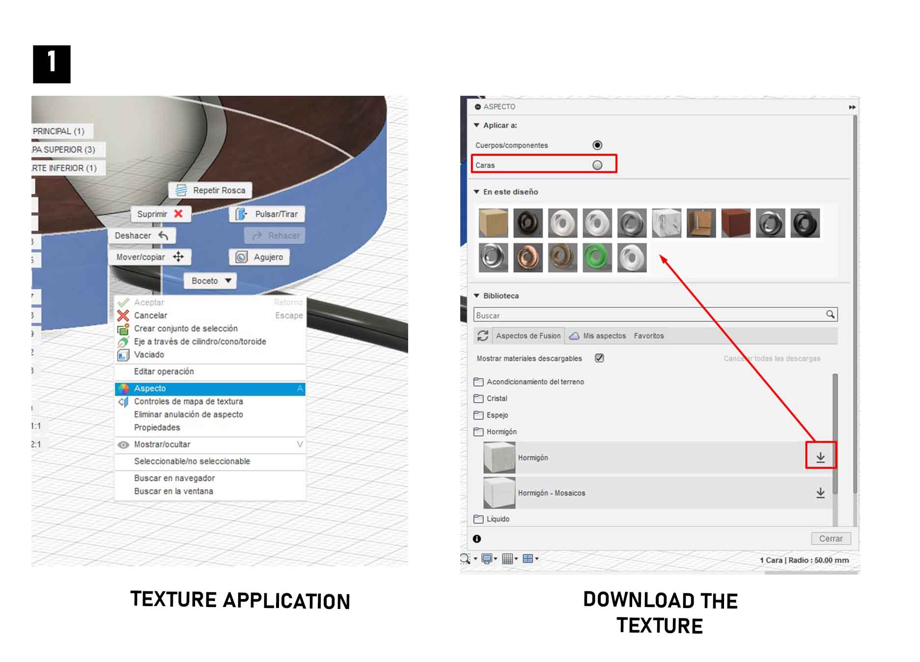
Now with all this I can start to place materials.
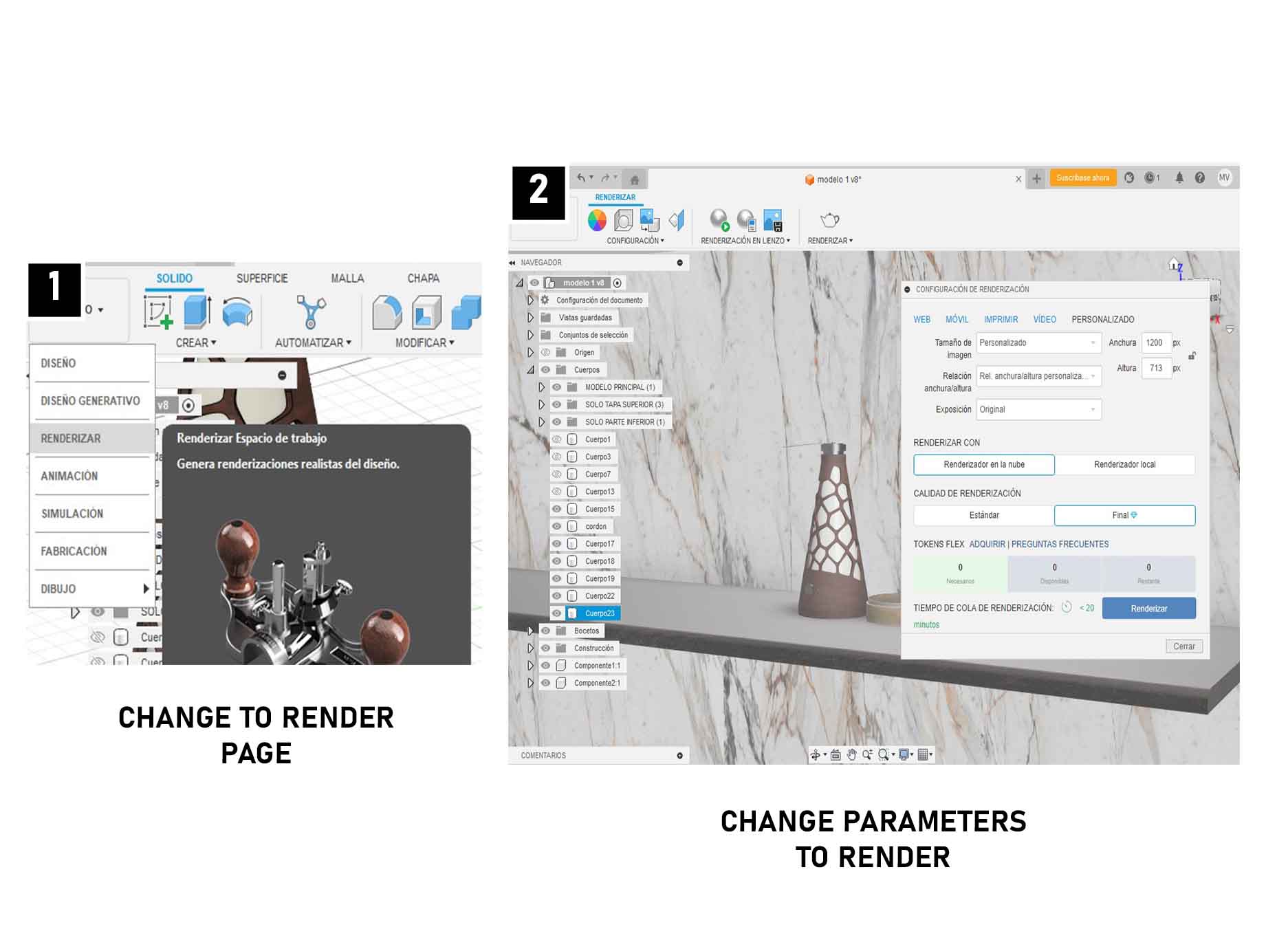
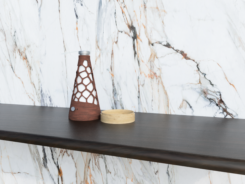
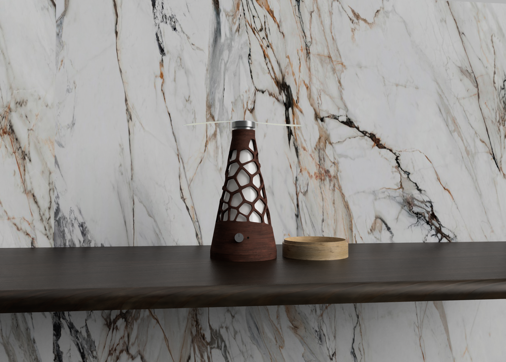
Rendering and starting animation
To make the render, I start defining a surface and an interesting background for my proposal, I change the program style to RENDER and from here I set my camera (zoom and framing) to start with the rendering configuration:
1. Select the CUSTOM style, so I can determine the image size, light exposure, quality and determine the time.
2. I give it accept to then wait in render on local for the total time.
3. I will be able to download the render in optimal quality and in png or jpg.
From here I am ready to continue with the animation.
Rendering and starting animation
To make the render, I start defining a surface and an interesting background for my proposal, I change the program style to RENDER and from here I set my camera (zoom and framing) to start with the rendering configuration:
1. select the CUSTOM style, so I can determine the image size, light exposure, quality and determine the time.
2. I give it accept to then wait in render on local for the total time.
3. I will be able to download the render in optimal quality and in png or jpg.
From here I am ready to continue with the animation.
Animation and post-production
To start with the animation, I change the program style and start defining, what I want to move, how the movement will be, how long it will last.
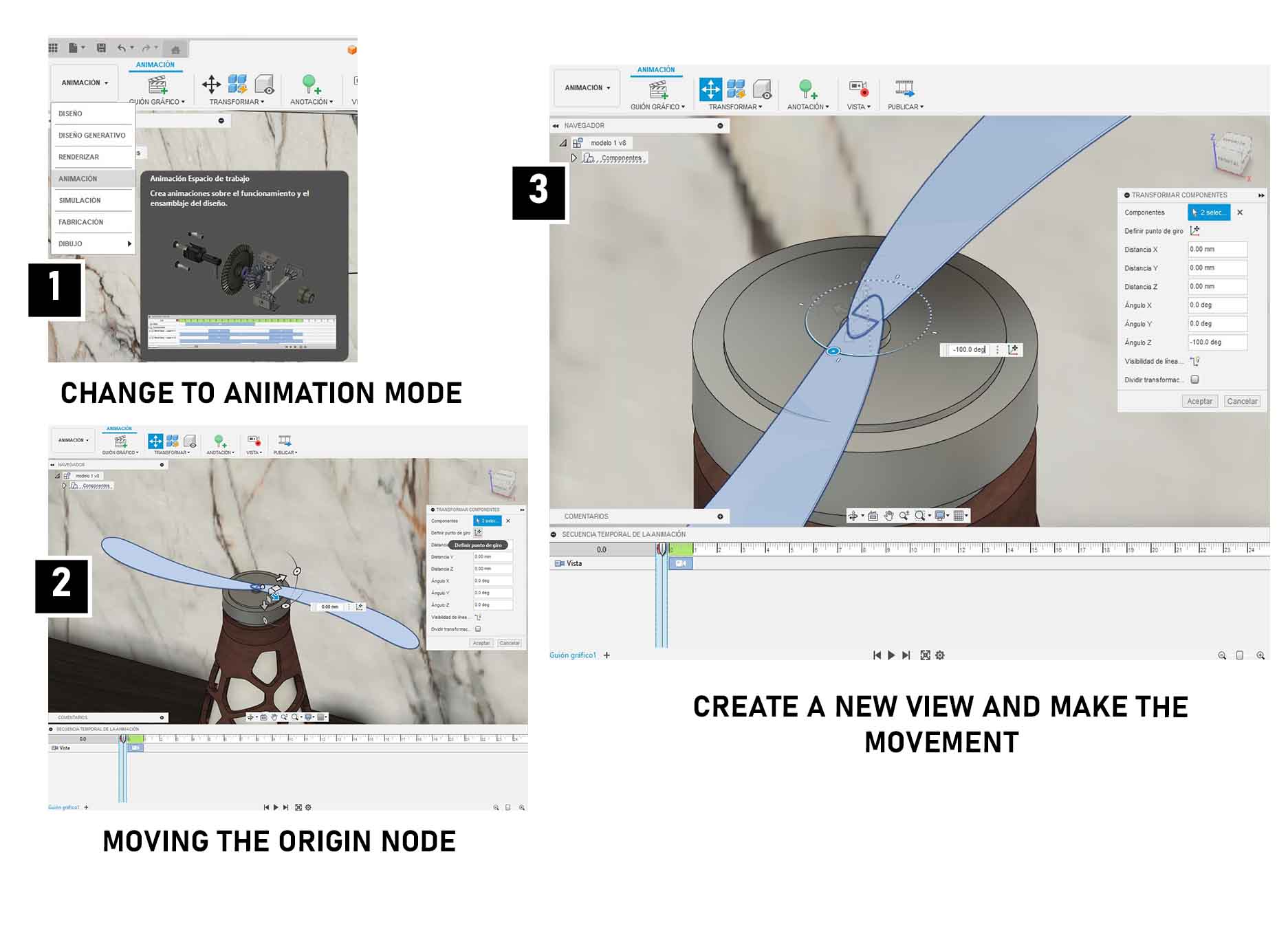
1. I select the two propellers and I give the tool TRANSFORM, then I select the DEFINE ROTATION POINT and select the center so that the rotation starts from there.
2. Once the rotation is defined and saved, with a click on the lower wheel, I start to rotate the two propellers from their base to achieve the rotation of -360°, it is worth mentioning that this is done from the definition of a frame in the timeline.
3. To define a frame I must do it with the command CT5RL + R, so that the movement is recorded and from that point the PLAY begins.
4. Once defined the movement I can export it to video to initiate the rendering and later postproduction, here the result, I helped myself with CLIMPCHAMP (I leave link of tutorial here)
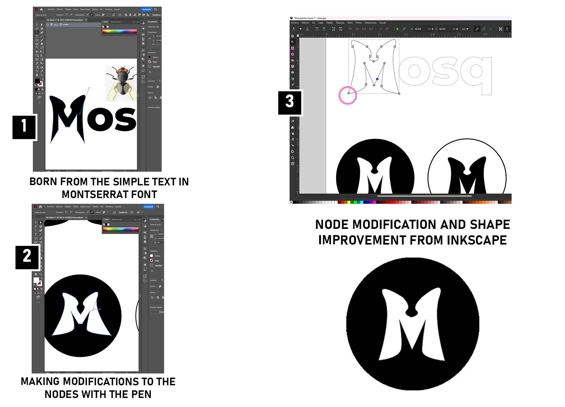
Logo design and visual identity
To make the logo, I used Illustrator, I also developed the logo in Inkscape, but against these two programs I am more comfortable working with Illustrator, here are some differences.
1. Inskcape is very easy to use, intuitive, very similar to Corel Draw.
2. Inskcape allows me to easily determine the vertices but not to modify them, maybe I need a little practice to be able to use it.
3. With Illustrator I define better what I want to do, in terms of colors, shapes, editing, I have more experience.
4. I like to draw a lot with PEN, it is a very simple tool to use and it is also complete to do many things at the same time.
5. To start with my drawing, I previously worked on the silhouette of my typography and from it I develop the 2D model, I think in the future I will do vinyl cutting tests to look for the best way to get the best results.
Final Video