This week's assignment was:
- Browse through the data sheet for your microcontroller
- Compare the performance and development workflows for other architectures
- Write a program for a microcontroller development board that you made to interact (with local input &/or output devices) and communicate (with remote wired or wireless devices)
- EXTRA CREDIT: Use different languages &/or development environments
- EXTRA CREDIT: Connect external components to the board
ORGANIZATION
Here I show how I organized myself for this week.
| Wednesday 28th: | Fab Academy classes |
|---|---|
| Thursday 29th: | Meeting and feedback with instructors. Progress of research group work |
| Friday 1th: | Meeting with colleagues from the FAB ACADEMY to finish the group assignment and learn about their research. Make documentation No. 1 |
| Saturday 2th: | Enter OPEN GLOBAL TIME. Move forward with the individual programming assignment with quentorres. |
| Sunday: 3th: | Documentation and commit of everything done until Saturday. |
| Monday 4th: | Advance and finish the individual assignment with all the inputs and outputs that we have in the FAB LAB. Documentation No. 3 |
| Tuesday 5th: | Documentation review, add some small changes and final commit. |
GROUP ASSIGNMENT
Here I leave the link to go to the group assignments page.
Clic here to visit the WEEK 6 GROUP ASSIGNMENT PAGE
To carry out the group work, on Thursday 02/29/2024 all the students met with our instructors to talk about the group and individual work and clarify some doubts we had for the week. They helped us a lot by giving us a short introduction to programming and explaining the assignments.
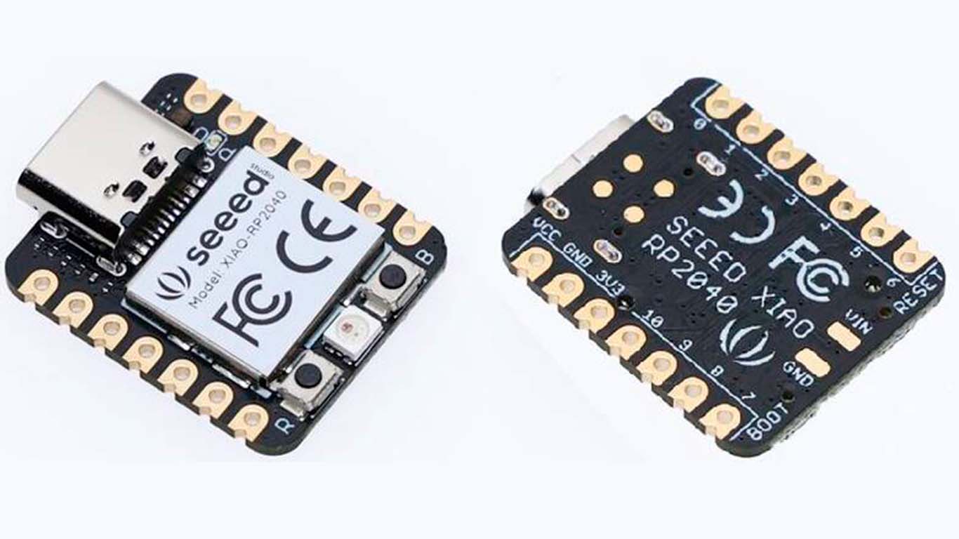
SEEED STUDIO XIAO RP2040 MICROCONTROLLER
INTRODUCTION
For the FAB ACADEMY 2024, they recommended that we use the SEEED STUDIO XIAO RP2040, which will help us carry out all our assignment programming and also our final work. It is a very powerful microcontroller that, due to its characteristics, allows us to program due to its versatility.
FEATURES
1. Raspberry Pi RP2040 Microcontroller: The RP2040 is an ARM Cortex-M0+ dual-core microcontroller running at 133 MHz. It offers a wide range of peripherals and exceptional performance for low-power applications.
2. USB-C Connectivity: The XIAO RP2040 board uses a USB-C port for power and programming, making it easy to connect and program the board to a variety of systems.
3. Arduino Compatibility: The XIAO RP2040 board is compatible with the Arduino development environment, allowing users to easily program it using the Arduino programming language and the wide range of libraries available.
4. Small form factor: The XIAO RP2040 board has a small form factor, making it ideal for applications where space is limited, such as wearables, wearable devices and sensors.
5. Support for multiple communication interfaces: The XIAO RP2040 board features a variety of communication interfaces, including UART, SPI, I2C and USB, making it suitable for a wide range of embedded electronics and IoT applications.
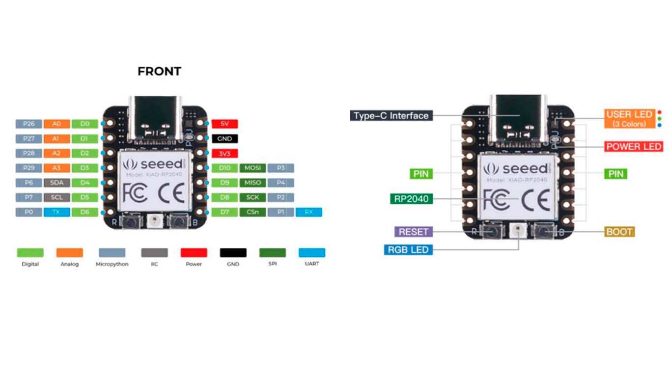
DATA SHEET SEEED STUDIO XIAO RP2040
Seed Studio XIAO RP2040 supports different programming languages such as C++, MicroPython, Python, Arduino IDE. It is also compatible with the Raspberry Pi RP2040 ecosystem and here I leave you some characteristics of the microcontroller:
- Microcontroller: RP2040 dual-core ARM Cortex-M0+ at 133 MHz.
- Memory: 264 KB of RAM and 2 MB of QSPI flash memory.
- Connectivity: USB-C for power and programming.
- Compatibility: Compatible with Arduino and CircuitPython development environment.
- Communication interfaces: UART, SPI, I2C, USB.
- Form factor: Small, ideal for limited space applications.
- Power: 3.3V.
- Peripherals: 30 GPIO pins, 2 status LEDs.
- Software Support: Support for multiple development environments, including Arduino, CircuitPython and MicroPython.
- Hardware Support:Support for a wide range of sensors and actuators.
- Applications: Ideal for IoT projects, embedded electronics, wearables and portable devices.
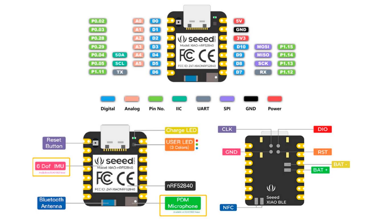
There are 14 GPIO PINs on Seeed Studio XIAO RP2040, which include 11 digital pins, 4 analog pins, 11 PWM Pins,1 I2C interface, 1 UART interface, 1 SPI interface, 1 SWD Bonding pad interface.
Here I leave the DATASHEET link of the microcontroller so that we can learn more features.
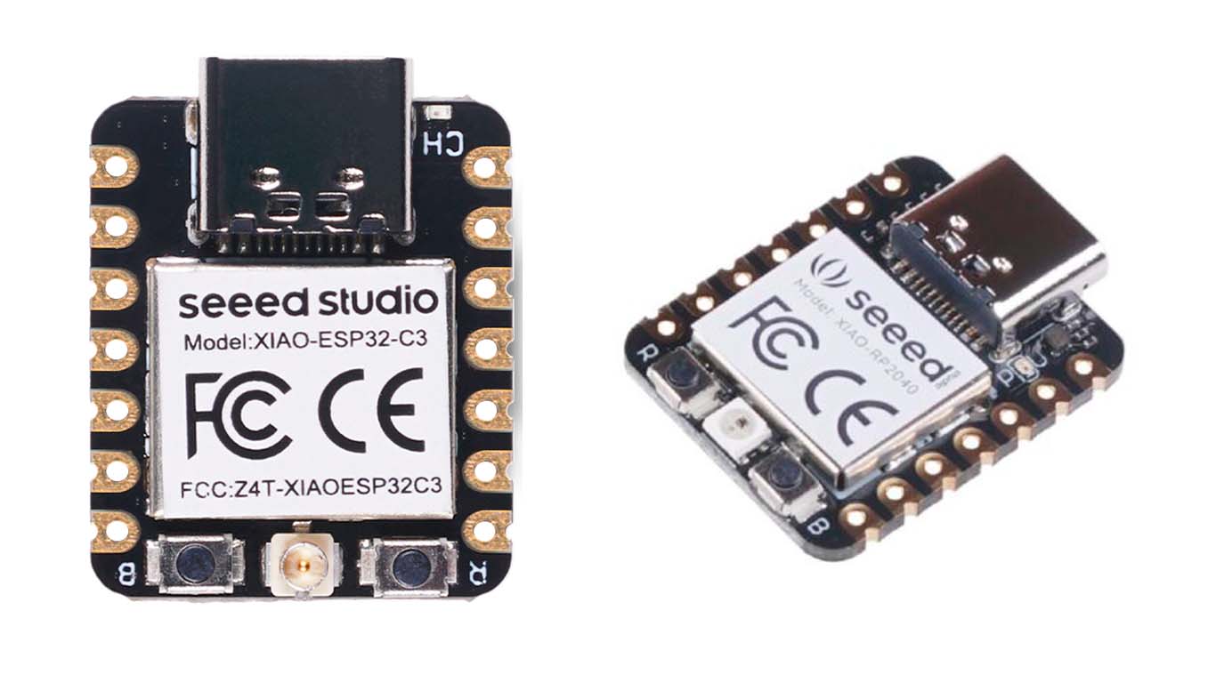
SEEED STUDIO XIAO ESP32-C3 MICROCONTROLLER
INTRODUCTION
Another microcontroller that they recommended to use is the SEEED STUDIO XIAO ESP32-C3 , which has very similar characteristics to the XIAO RP2040, however, it has some differences that will be explained later.
FEATURES
1. ESP32-C3 Microcontroller: The ESP32-C3 is a single-core RISC-V microcontroller running at 160 MHz. It offers a wide range of peripherals and exceptional performance for low-power applications.
2. USB-C Connectivity: The XIAO ESP32-C3 board uses a USB-C port for power and programming, making it easy to connect and program the board to a variety of systems.
3. Arduino Compatibility: The XIAO ESP32-C3 board is compatible with the Arduino development environment, allowing users to easily program it using the Arduino programming language and the wide range of libraries available.
4. CircuitPython and MicroPython Support: In addition to being compatible with the Arduino development environment, the XIAO ESP32-C3 board also supports CircuitPython and MicroPython, two popular programming languages for microcontrollers. This expands development options and allows users to choose the environment that best suits their needs and preferences.
5. Support for Bluetooth and Wi-Fi: The ESP32-C3 has wireless connectivity capabilities, allowing the XIAO ESP32-C3 board to communicate with other devices via Bluetooth and Wi-Fi. This is especially useful for IoT applications and creating network-connected devices.
DATA SHEET SEEED STUDIO XIAO ESP32-C3
Seed Studio XIAO RP2040 supports different programming languages such as C++, MicroPython, Python, Arduino IDE. It is also compatible with the Raspberry Pi RP2040 ecosystem and here I leave you some characteristics of the microcontroller:
- Microcontroller:ESP32-C3, a single-core RISC-V microcontroller running at 160 MHz.
- Memory: 400 KB de RAM y 384 KB de memoria flash.
- Connectivity: USB-C for power and programming, and support for Bluetooth and Wi-Fi.
- Compatibility: Compatible with Arduino, CircuitPython and MicroPython development environments.
- Communication interfaces: UART, SPI, I2C, USB and microSD card support.
- Form factor: Small, ideal for limited space applications.
- Power: 3.3V.
- Peripherals: Connector for external antenna, connector for lithium battery and 30 GPIO pins.
- Software Support: Support for multiple development environments, including Arduino, CircuitPython and MicroPython.
- Applications: Ideal for IoT projects, embedded electronics, wearables and portable devices.
There are 11 digital I/O that can be used as PWM pins and 6 analog I/O that can be used as ADC pins. It supports all three common serial interfaces such as UART, I2C, and SPI.
Here I leave the DATASHEET link of the microcontroller so that we can learn more features.
COMPARISON WITH OTHER ARCHITECTURES
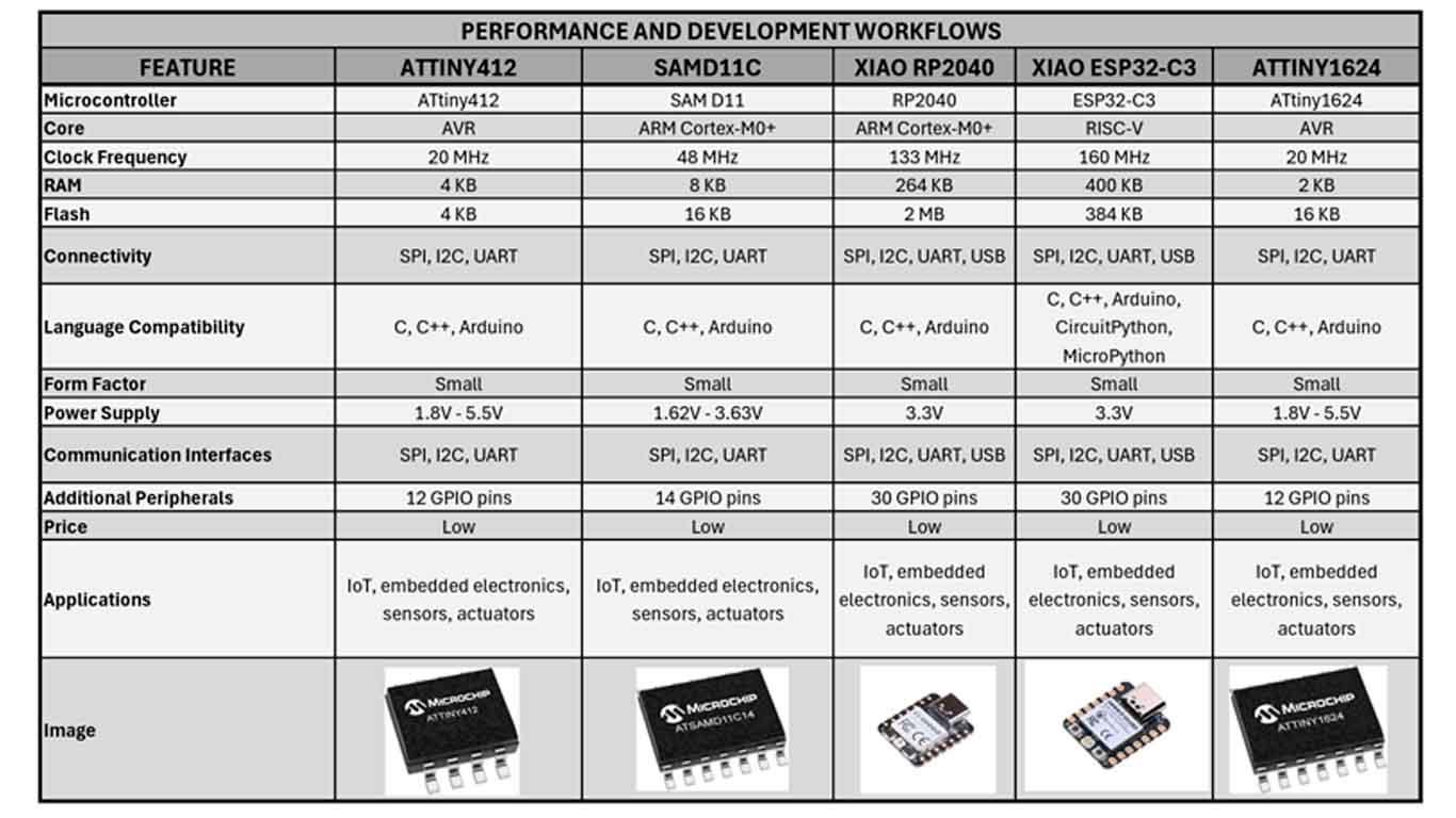
COMPARISON TABLE
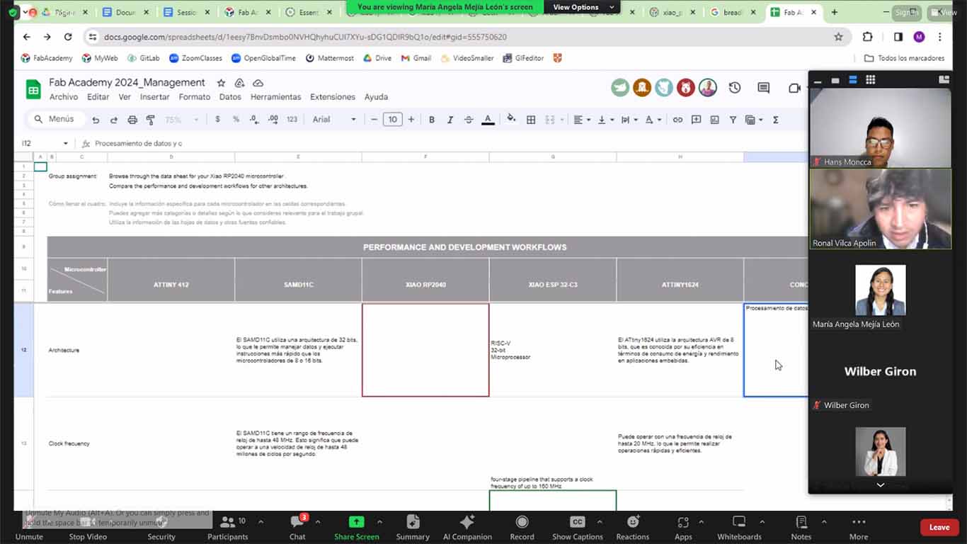
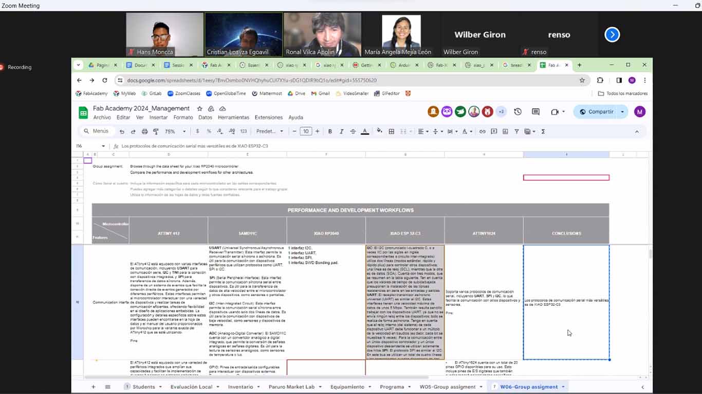
To make the comparison table of the different microcontrollers that the FAB ACADEMY recommended to us, we held a virtual meeting to talk, share information and we assigned ourselves by group for the research. Here I leave a screenshot of the summary table of everything done in the group. After that, I leave a final conclusion of what I learned and how important it is to know about other microcontrollers that we may use in our final project.
Here I leave the PDF FILE of the research carried out in summary.
CONCLUSION
All microcontrollers have unique features and can be suitable for different types of projects. For example, the ATTINY412 is ideal for low-power applications due to its low power consumption and wide range of peripherals. The SAMD11C is a great choice for projects that require high processing power and a wide range of communication interfaces. The XIAO RP2040 and XIAO ESP32-C3 are excellent options for IoT and embedded electronics projects due to their wireless connectivity and wide range of peripherals. The ATTINY1624 is ideal for budget-friendly projects due to its low cost and wide range of peripherals. Overall, choosing the right microcontroller will depend on the specific needs of your project, such as performance, connectivity, power consumption, and cost.
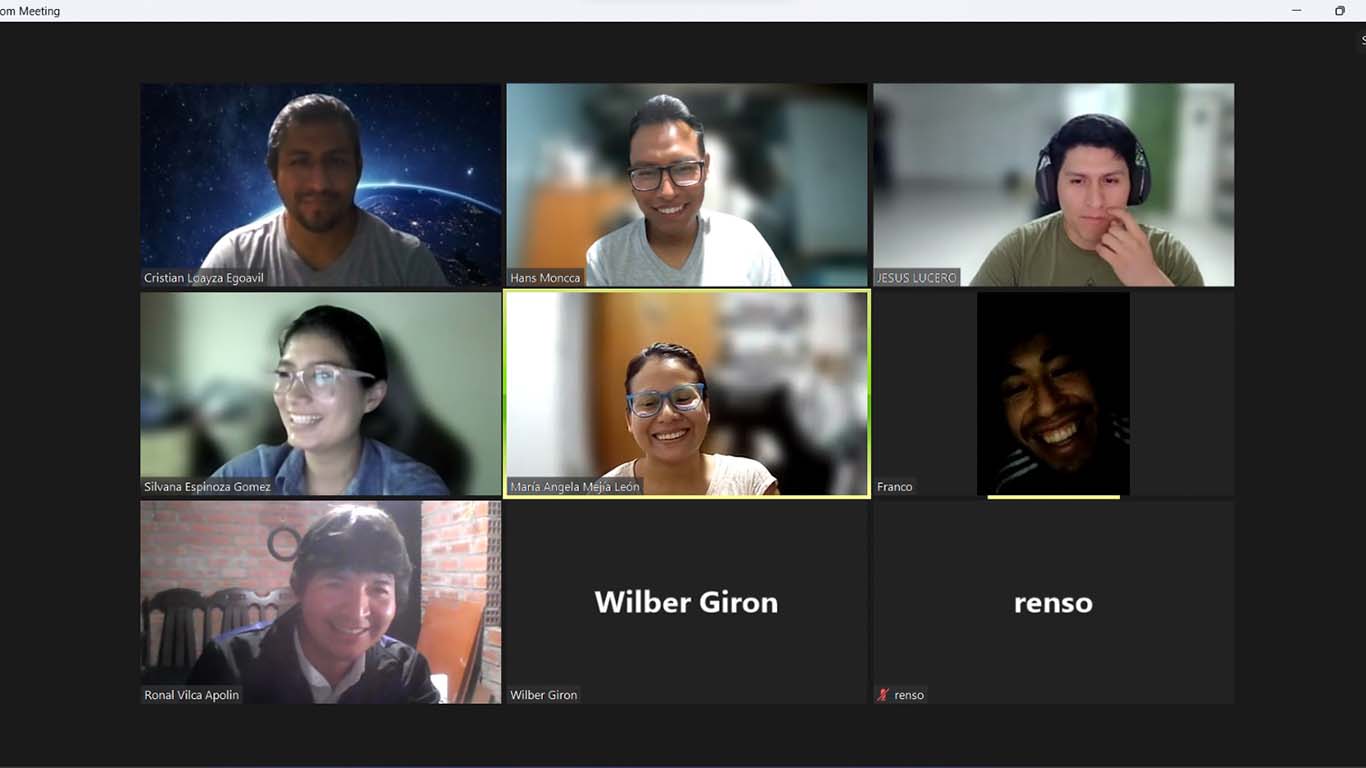
We carried out the comparison of microcontrollers virtually where we met until very late, but we learned a lot about their differences, we learned to know more programming and electronics terms. Finally, here is a photo of us when we finished the group work, all very tired but with the strength to continue with the FAB ACADEMY.
INDIVIDUAL ASSIGNMENT
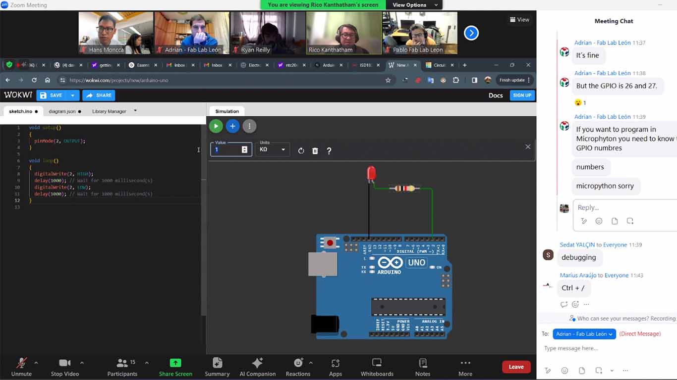
To develop the individual work it was difficult where to start since I have zero knowledge in programming. For this reason, I joined the OPEN GLOBAL TIME on Saturday 03/02/2024 where, especially the teacher Adrian and Rico, explained to us how we could work, what the objective of the assignments is and help us see if we accomplished something. On my part I had nothing because I didn't know where to start. The meeting helped me a lot and they recommended me to "PLAY" with the Quentorres and programming the LEDs they have.
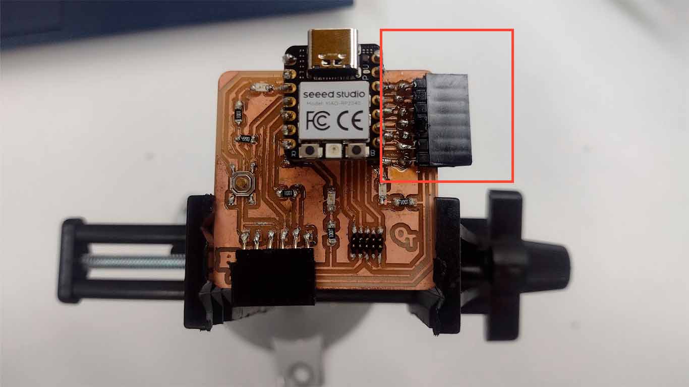
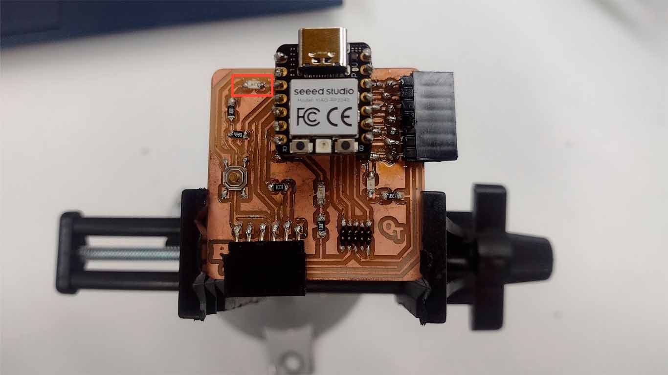
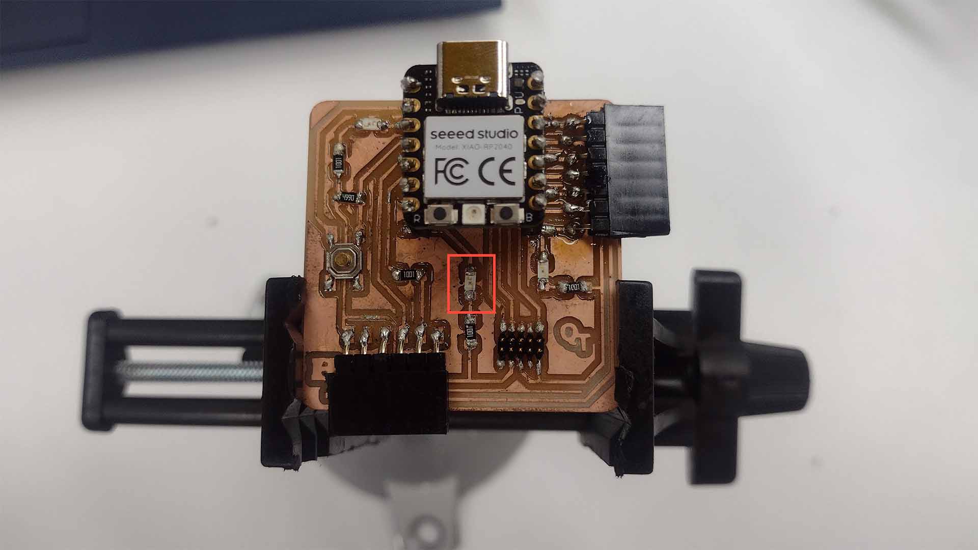
Here I have a photo of the QUENTORRES where they recommended soldering a component to be able to program different IMPUTS or OUTPUTS.
PROGRAMMING WITH ARDUINO IDE
INSTALL AND CONFIGURATION ARDUINO IDE
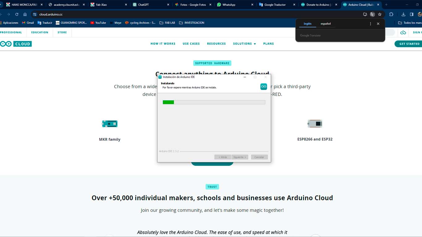
To start programming QUENTORRES components I will start using the ARDUINO IDC that we were recommended to use for beginners. From here I will show different programming that I did with the LEDs that the board has. First of all, we are going to install the ARDUINO.IDC program and from there start programming.
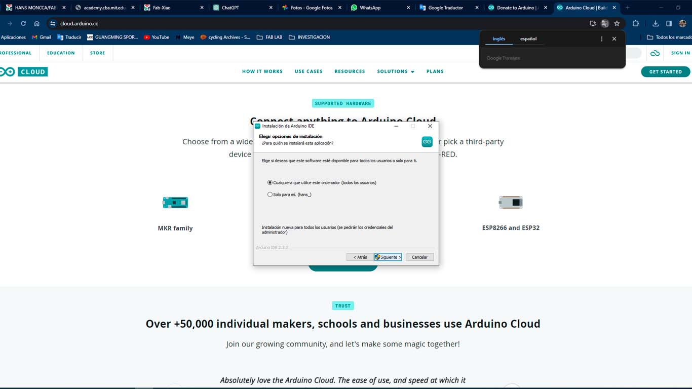
After installing the program, we need to configure to be able to program the XIAO RP2040, so we have to follow the following steps:
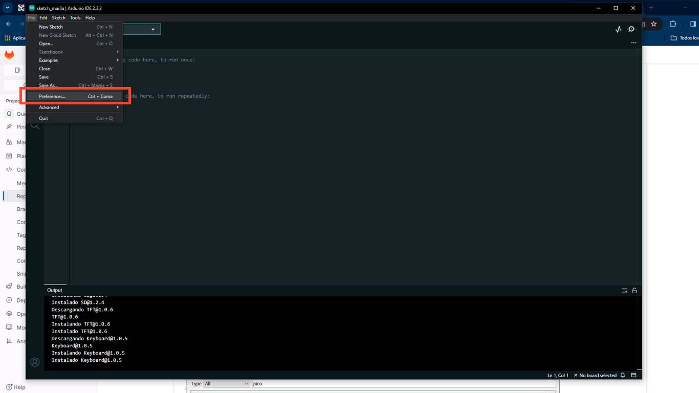
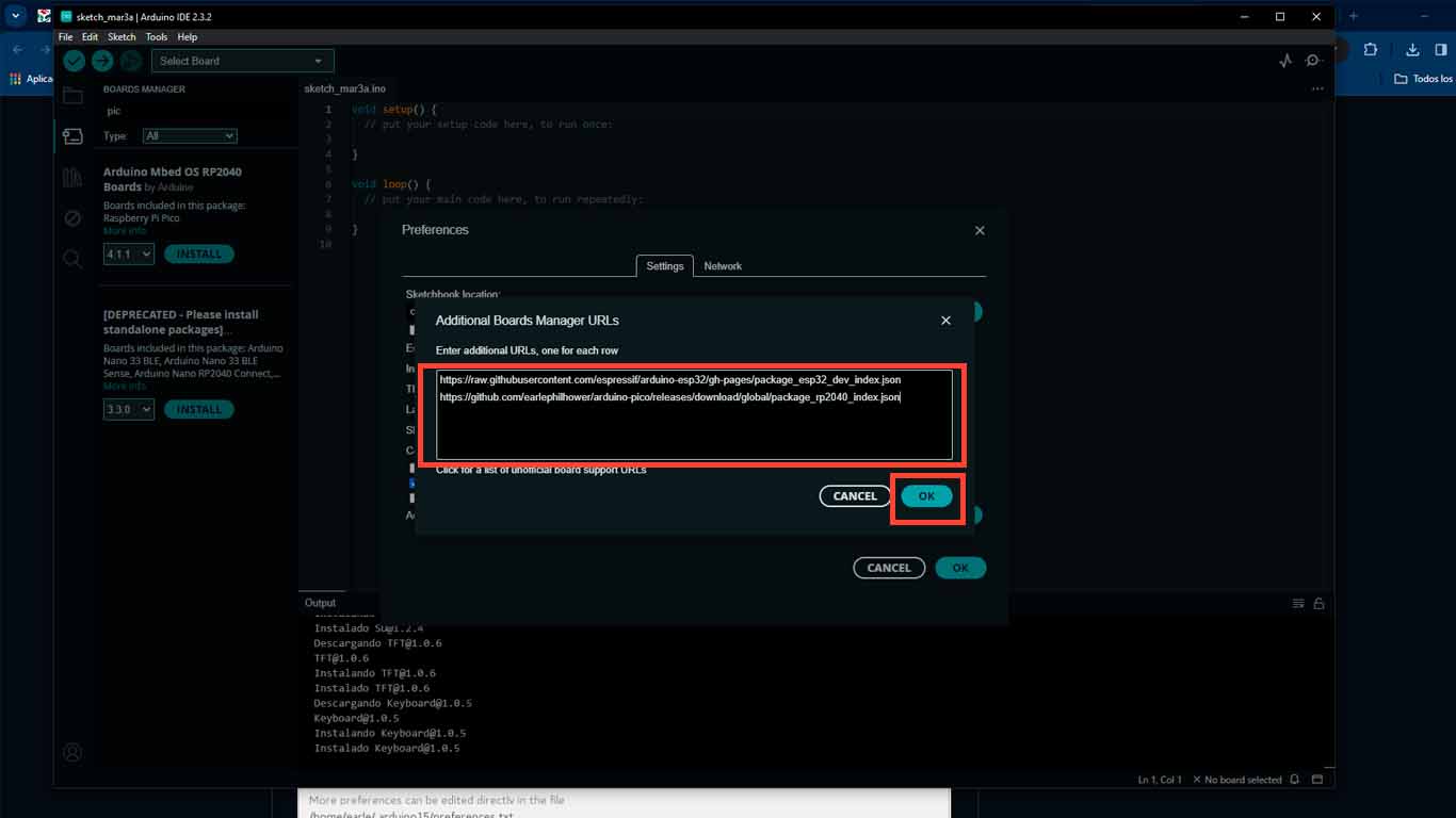
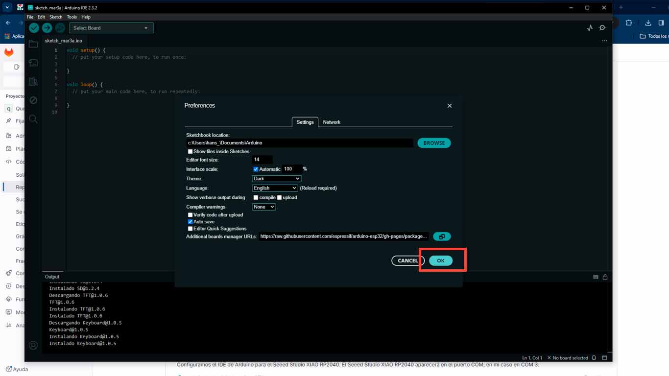
Being in the program we go to FILES/PREFERENCES , here we will add 2 links so that the program can download all the information about the XIAO RP2040. Here I leave the 2 links that you need to copy and paste in the ADDITIONAL BOARDS section.Finally we click OK and it will begin downloading all the necessary information.
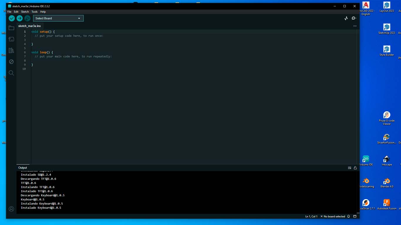
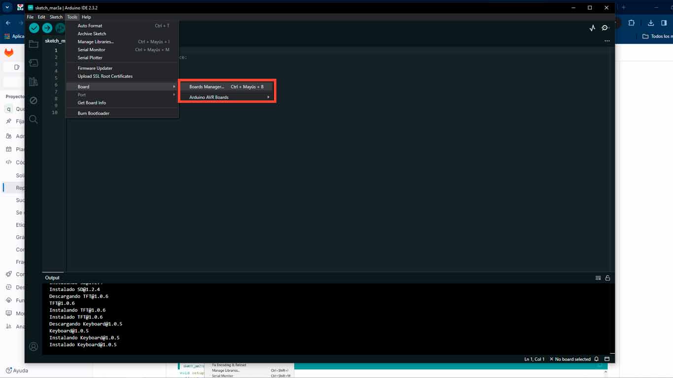
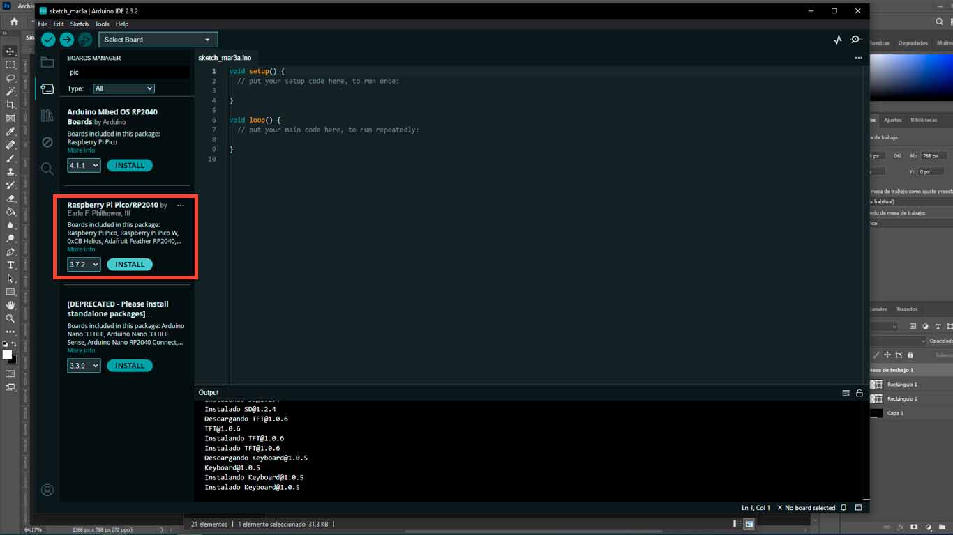
Then we go to TOOLS/BOARD/BOARDS MANAGER , a tab will appear where we will put the word PICO and we will install the document called RASPBERRY PI PICO / RP2040 .
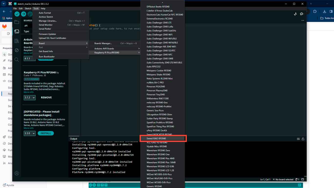
Finally, we look in TOOLS/BOARD/RASPBERRY PI PICO/RP2040 and look for our SEEED XIAO RP2040 processor. This confirms that the installation is correct and we can start programming.
BLINK A LED
We will start to BLINK the first LED that is connected to PIN 26 or D0 . This without activating something, just programming a simple blink and seeing if it works.
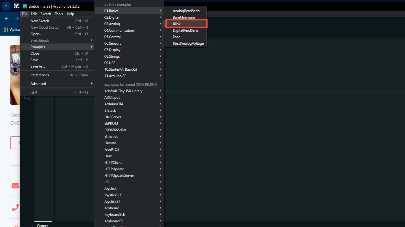
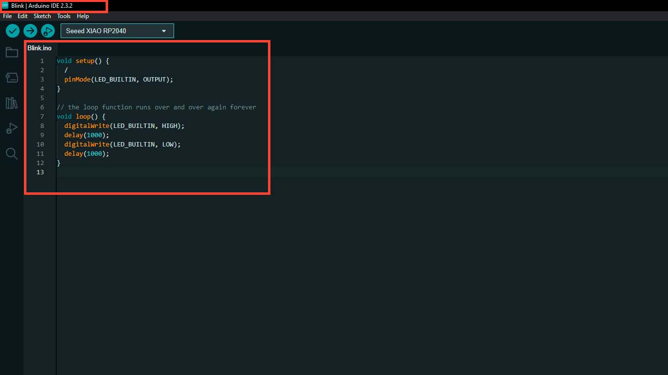
To perform the BLINK , we can start with an example that the ARDUINO IDE has. To do this, we can go to FILES/EXAMPLES/01.BASICS/BLINK. Here an ARDUINO IDE tab will open with the name BLINK. Here we can start programming the LED BLINK
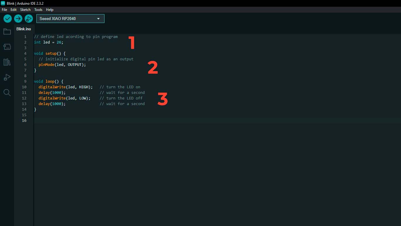
To program in ARDUINO IDE I understood that we have 3 important parts. The DEFINITION, VOID SETUP and VOID LOOP. Where in the first we have to define the PIN where the PIN is located; In VOID SETUP we set the LED as the output and in VOID LOOP we set the time and blink that the LED will have.
After checking that everything is fine, we click on VERIFY in the upper left and after that, we click on UPLOAD where we load the information into QUENTORRES and we will see the magic.
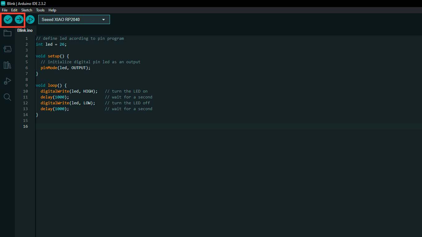
Here I leave the code for ARDUINO IDE
                                // define led acording to pin program
                                int led = 26;
                                void setup() {
                                // initialize digital pin led as an output
                                pinMode(led, OUTPUT);
                                }
                                void loop() {
                                digitalWrite(led, HIGH);   // turn the LED on
                                delay(1000);               // wait for a second
                                digitalWrite(led, LOW);    // turn the LED off
                                delay(1000);               // wait for a second
                                }
We can see that the LED on pin 26 or D0 does BLINK according to the data mentioned in the program.
INPUT
BUTTON PROGRAMMING
For the following programming we will make the button that we have in PIN 27 or D1 turn on the LED of PIN 26 or D0 that we have and when pressed it will have to blink for 3 times and then turn off. To do this, we will follow the same steps as the previous exercise, we will only add the button PIN and see if it is possible.
In the first part, we specify the LED and BUTTON pins, along with their state and intensity variables. In the second part we add the 2 BUTTON pins and specify which one is the OUTPUT and INPUT. In the third part, we add the number of blinks that the LED will make when pressing the button and finally, set a condition when not pressing the button, the LED will be off.
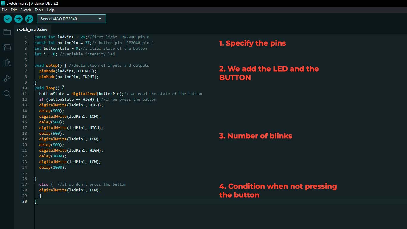
Here I leave the programming code for ARDUINO.IDE when pressing the button
                                const int ledPin1 = 26;//first light  RP2040 pin 0
                                const int buttonPin = 27;// button pin  RP2040 pin 1
                                int buttonState = 0;//initial state of the button
                                int i = 0; //variable intensity led

                                void setup() { //declaration of inputs and outputs
                                pinMode(ledPin1, OUTPUT);
                                pinMode(buttonPin, INPUT);
                                }
                                void loop() {
                                buttonState = digitalRead(buttonPin);// we read the state of the button
                                if (buttonState == HIGH) { //if we press the button
                                digitalWrite(ledPin1, HIGH);
                                delay(500);
                                digitalWrite(ledPin1, LOW);
                                delay(500);
                                digitalWrite(ledPin1, HIGH);
                                delay(500);
                                digitalWrite(ledPin1, LOW);
                                delay(500);
                                digitalWrite(ledPin1, HIGH);
                                delay(2000);
                                digitalWrite(ledPin1, LOW);
                                delay(1000);

                                }
                                else {  //if we don't press the button
                                digitalWrite(ledPin1, LOW);
                                }
                                }
We can see that the LED flashes 3 times when the button is pressed. Here I demonstrate the video.
SEQUENCE PROGRAMMING WITH BUTTON
For the next exercise we will do that, by pressing the button, we will have a series of turning on all the QUENTORRES LEDs, where the sequence will be repeated 4 times. The sequence will have this PIN LED D0; PIN LED D6 and PIN LED D7 and the shutdown will be carried out in reverse and all this will be repeated 4 times. In addition, we will add a message that, when we press the button, a “HELLO” message will appear in the SERIAL MONITOR of the Arduino IDE. Here the code and programming result
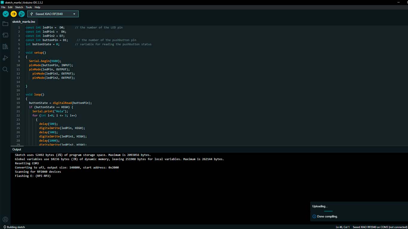
Here I leave the programming code made that works very well for me. You can see the video.
                                const int ledPin =  D0;      // the number of the LED pin
                                const int ledPin1 =  D6;
                                const int ledPin2 = D7;
                                const int buttonPin = D1;     // the number of the pushbutton pin
                                int buttonState = 0;         // variable for reading the pushbutton status

                                void setup()
                                {
                                Serial.begin(9600);
                                pinMode(buttonPin, INPUT);
                                pinMode(ledPin, OUTPUT);
                                    pinMode(ledPin1, OUTPUT);
                                    pinMode(ledPin2, OUTPUT);

                                }

                                void loop()
                                {
                                    buttonState = digitalRead(buttonPin);
                                    if (buttonState == HIGH) {
                                        Serial.print("Hola");
                                        for (int i=0; i <= 3; i++)
                                        {
                                            delay(500);
                                            digitalWrite(ledPin, HIGH);
                                            delay(500);
                                            digitalWrite(ledPin1, HIGH);
                                            delay(1000);
                                            digitalWrite(ledPin2, HIGH);
                                            delay(1000);
                                            digitalWrite(ledPin2, LOW);
                                            delay(1000);
                                            digitalWrite(ledPin1, LOW);
                                            delay(1000);
                                            digitalWrite(ledPin, LOW);

                                        }
                                } else {
                                        digitalWrite(ledPin, LOW);
                                        digitalWrite(ledPin1, LOW);
                                        digitalWrite(ledPin2, LOW);
                                    }
                                }
From the previous code, we can start playing and change the LED lighting sequence, now I will change the sequence and we will see that the lighting changes when the button is pressed. We only need to change the top part of the above file and we can see the changes.
                                const int ledPin =  D0;      // the number of the LED pin
                                const int ledPin1 =  D7;
                                const int ledPin2 = D6;
                                const int buttonPin = D1;     // the number of the pushbutton pin
                                int buttonState = 0;         // variable for reading the pushbutton status
OUTPUT
ULTRASOUND PROGRAMMING
For the next test we will do it with an output that is ULTRASOUND, in this case we will use it to measure the distance between the objects. The idea is to see how it works. Here I leave the programming code.
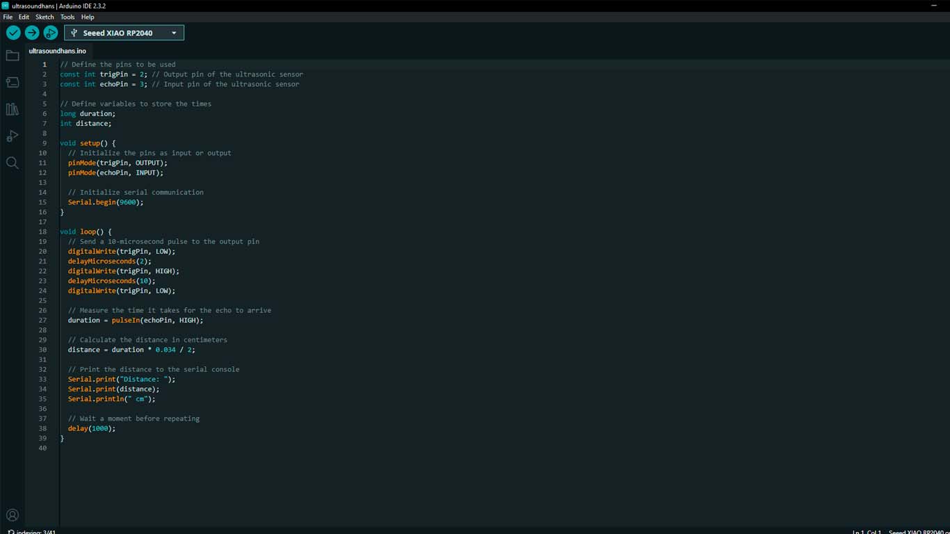
Here I leave a programming code where with the help of CHATGPT I was able to obtain and we can see the results.
                                // Define the pins to be used
                                    const int trigPin = 2; // Output pin of the ultrasonic sensor
                                    const int echoPin = 3; // Input pin of the ultrasonic sensor

                                    // Define variables to store the times
                                    long duration;
                                    int distance;

                                    void setup() {
                                    // Initialize the pins as input or output
                                    pinMode(trigPin, OUTPUT);
                                    pinMode(echoPin, INPUT);

                                    // Initialize serial communication
                                    Serial.begin(9600);
                                    }

                                    void loop() {
                                    // Send a 10-microsecond pulse to the output pin
                                    digitalWrite(trigPin, LOW);
                                    delayMicroseconds(2);
                                    digitalWrite(trigPin, HIGH);
                                    delayMicroseconds(10);
                                    digitalWrite(trigPin, LOW);

                                    // Measure the time it takes for the echo to arrive
                                    duration = pulseIn(echoPin, HIGH);

                                    // Calculate the distance in centimeters
                                    distance = duration * 0.034 / 2;

                                    // Print the distance to the serial console
                                    Serial.print("Distance: ");
                                    Serial.print(distance);
                                    Serial.println(" cm");

                                    // Wait a moment before repeating
                                    delay(1000);
                                    }
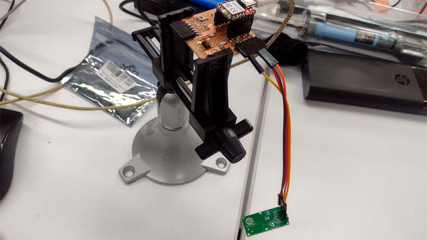
MOTION SENSOR TEST
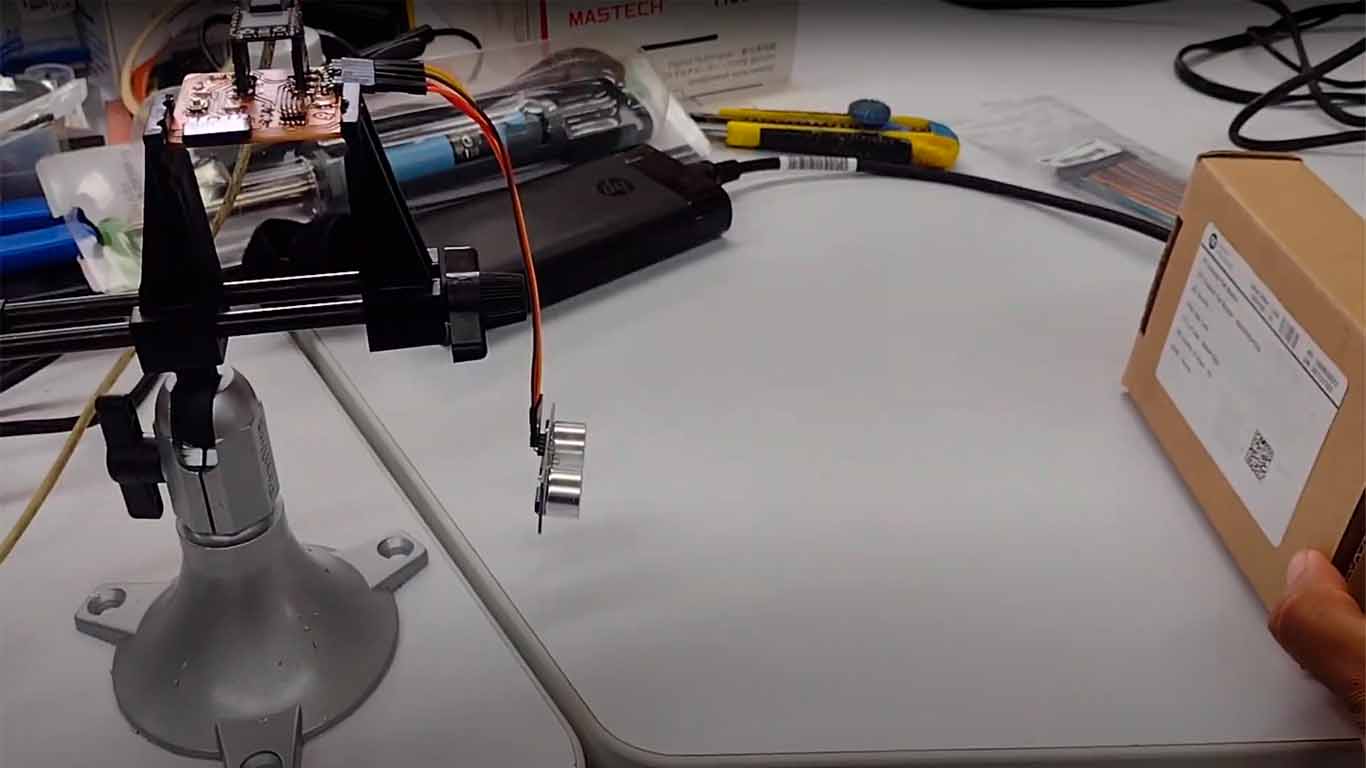
For the next test we will do it with an output that is MOTION DIRECTION DISTANCE 5-7m, in this case we will use it to detect movement within the range that the component has. Here I show you how we installed it and leave the programming code.
Here we can see how the sensor begins to detect movement and shows it through No. 1 and when there is no presence of movement it changes to No. 0, so we can confirm that the programming and the sensor work.
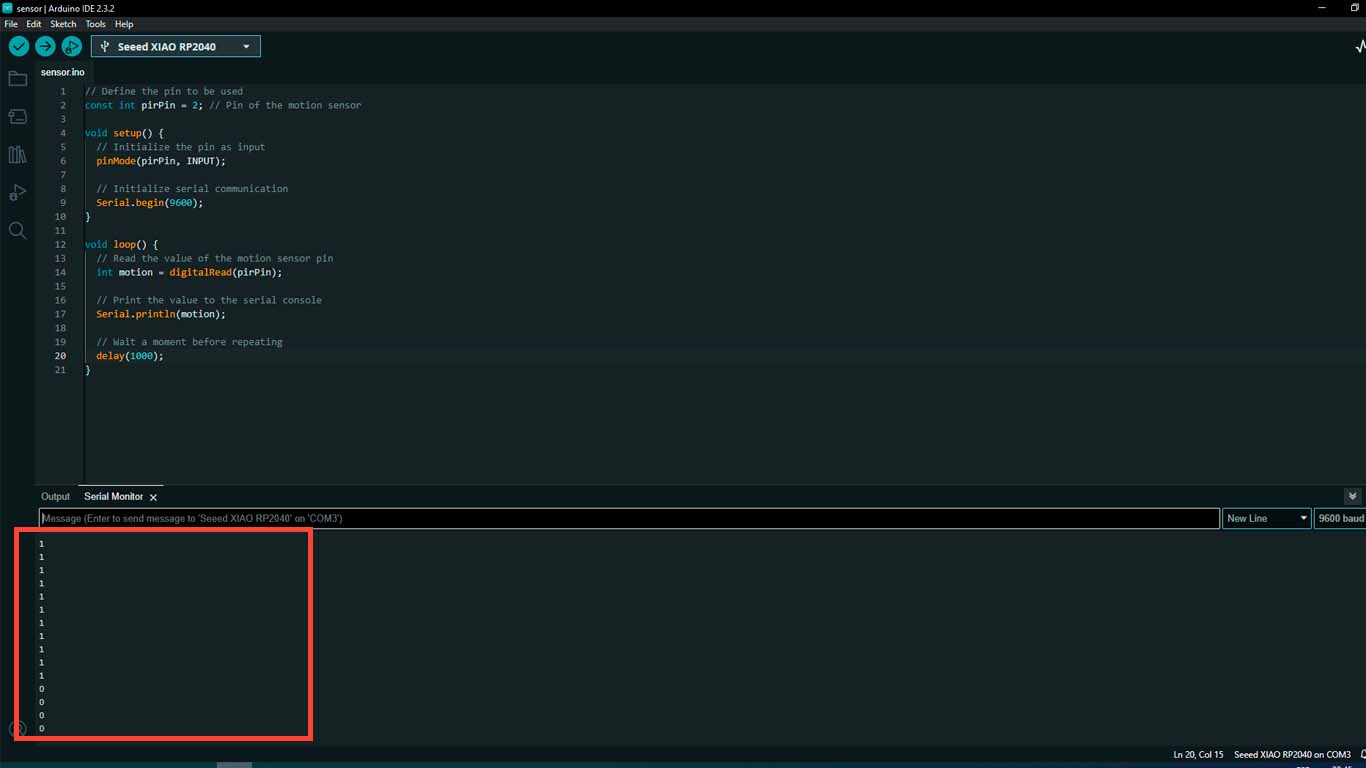
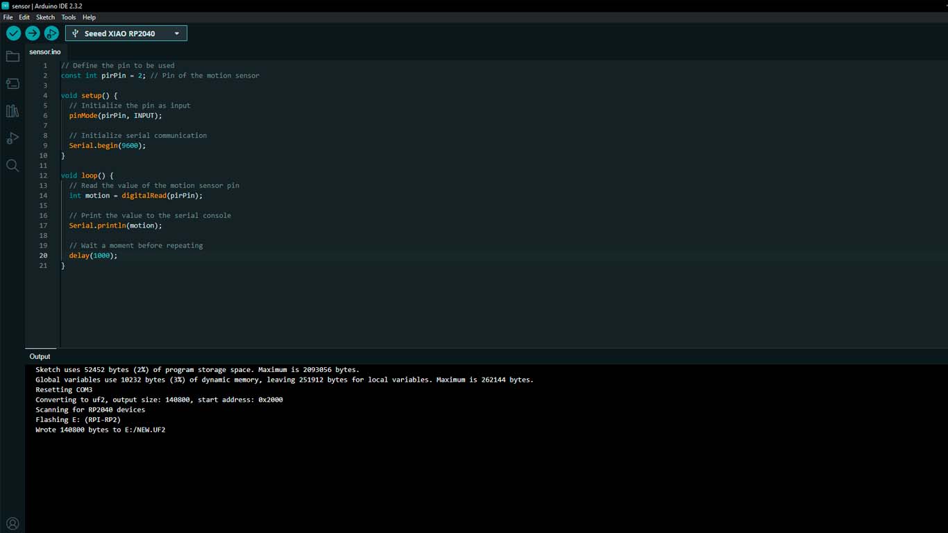
Here I leave a programming code where with the help of CHATGPT I was able to obtain and we can see the results.
                                // Define the pin to be used
                                    const int pirPin = 2; // Pin of the motion sensor

                                    void setup() {
                                    // Initialize the pin as input
                                    pinMode(pirPin, INPUT);

                                    // Initialize serial communication
                                    Serial.begin(9600);
                                    }

                                    void loop() {
                                    // Read the value of the motion sensor pin
                                    int motion = digitalRead(pirPin);

                                    // Print the value to the serial console
                                    Serial.println(motion);

                                    // Wait a moment before repeating
                                    delay(1000);
                                    }
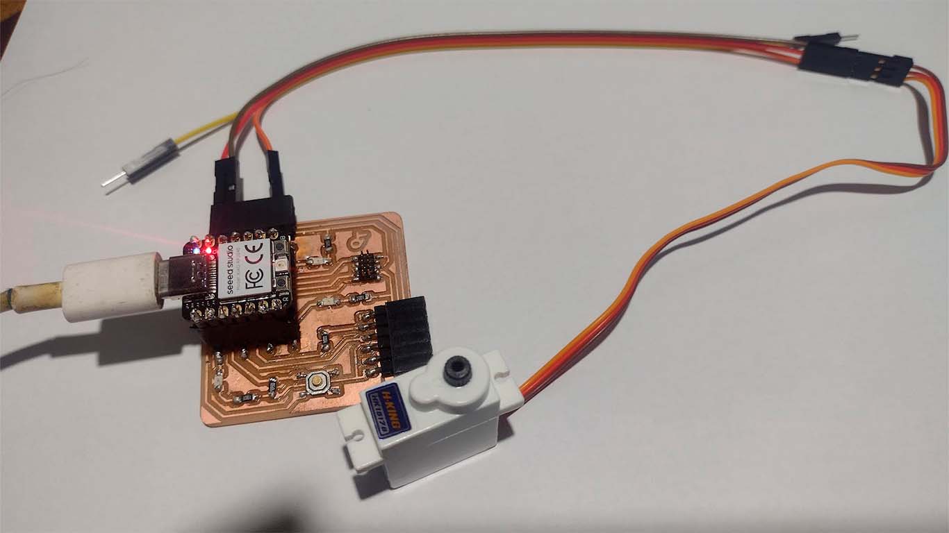
STANDARD SERVO MOTOR
Finally we will try to program a STANDARD SERVO MOTOR , in this case we will make the servo present a movement of 180° and return again. The idea is to check if both the programming and the component work. Here I show you its connection, its programming code and the movement it performs.
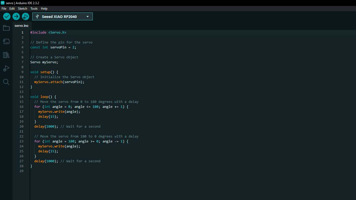
Here I leave a programming code where with the help of CHATGPT I was able to obtain and we can see the results.
                                #include

                                    // Define the pin for the servo
                                    const int servoPin = 2;

                                    // Create a Servo object
                                    Servo myServo;

                                    void setup() {
                                      // Initialize the Servo object
                                      myServo.attach(servoPin);
                                    }

                                    void loop() {
                                      // Move the servo from 0 to 180 degrees with a delay
                                      for (int angle = 0; angle <= 180; angle += 1) {
                                        myServo.write(angle);
                                        delay(15);
                                      }
                                      delay(1000); // Wait for a second

                                      // Move the servo from 180 to 0 degrees with a delay
                                      for (int angle = 180; angle >= 0; angle -= 1) {
                                        myServo.write(angle);
                                        delay(15);
                                      }
                                      delay(1000); // Wait for a second
                                    }
PROGRAMMING WITH THONNY - PYTHON
INSTALL AND CONFIGURATION THONNY
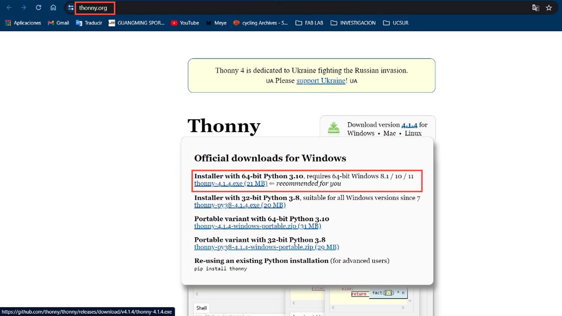
On the other hand, I also wanted to learn how to use THONNY, which is another type of language that also allows us to program the XIAO RP2040. The idea is to learn how to use it and program LEDS as well as some INPUT and OUTPUT similar to what was done with programming in ARDUINO IDE. First we go to our browser and look for THONNY PYTHON where we can download the program according to our type of operating system.
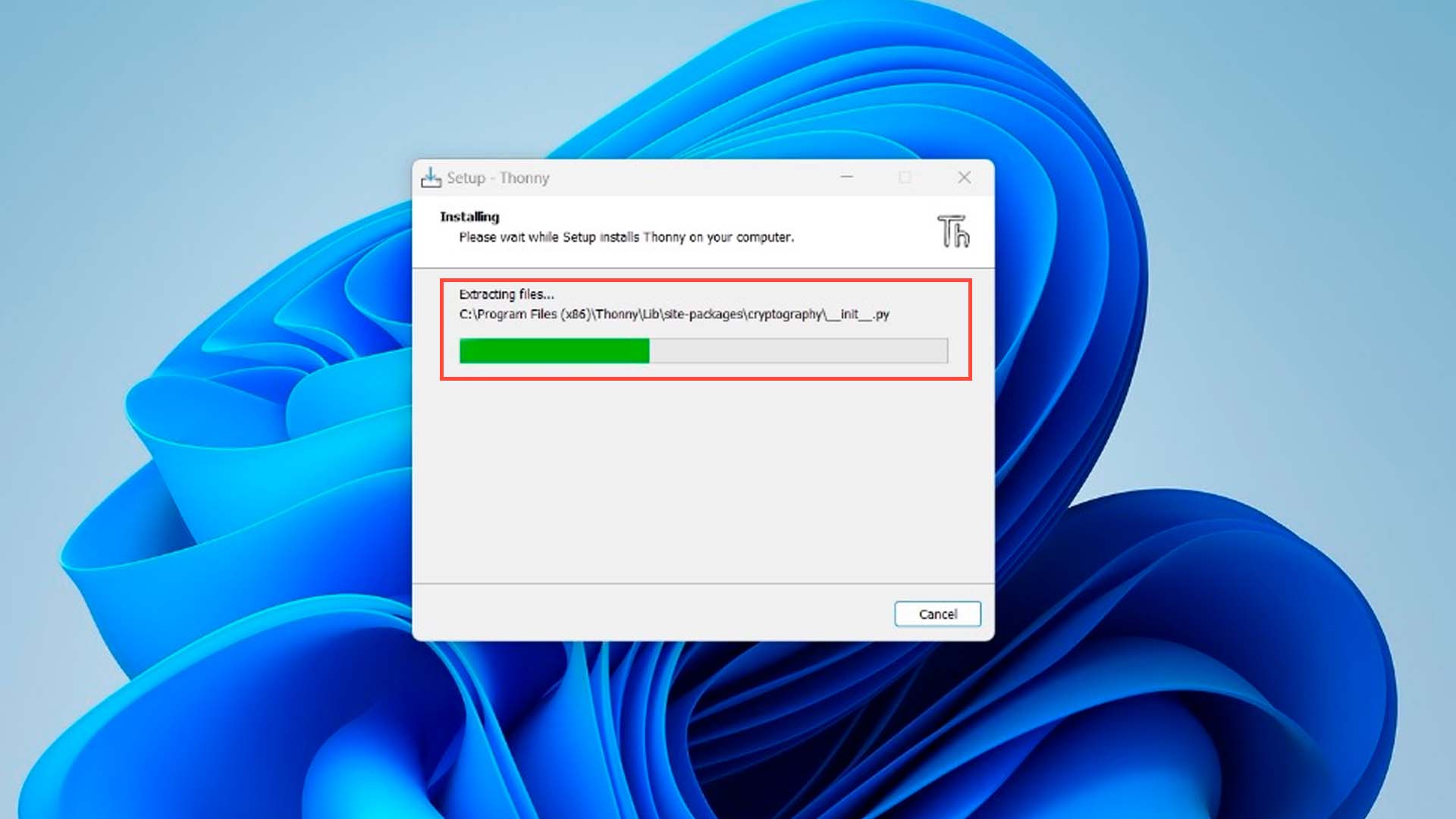
Then we carry out the different steps to install the program until we can install it.
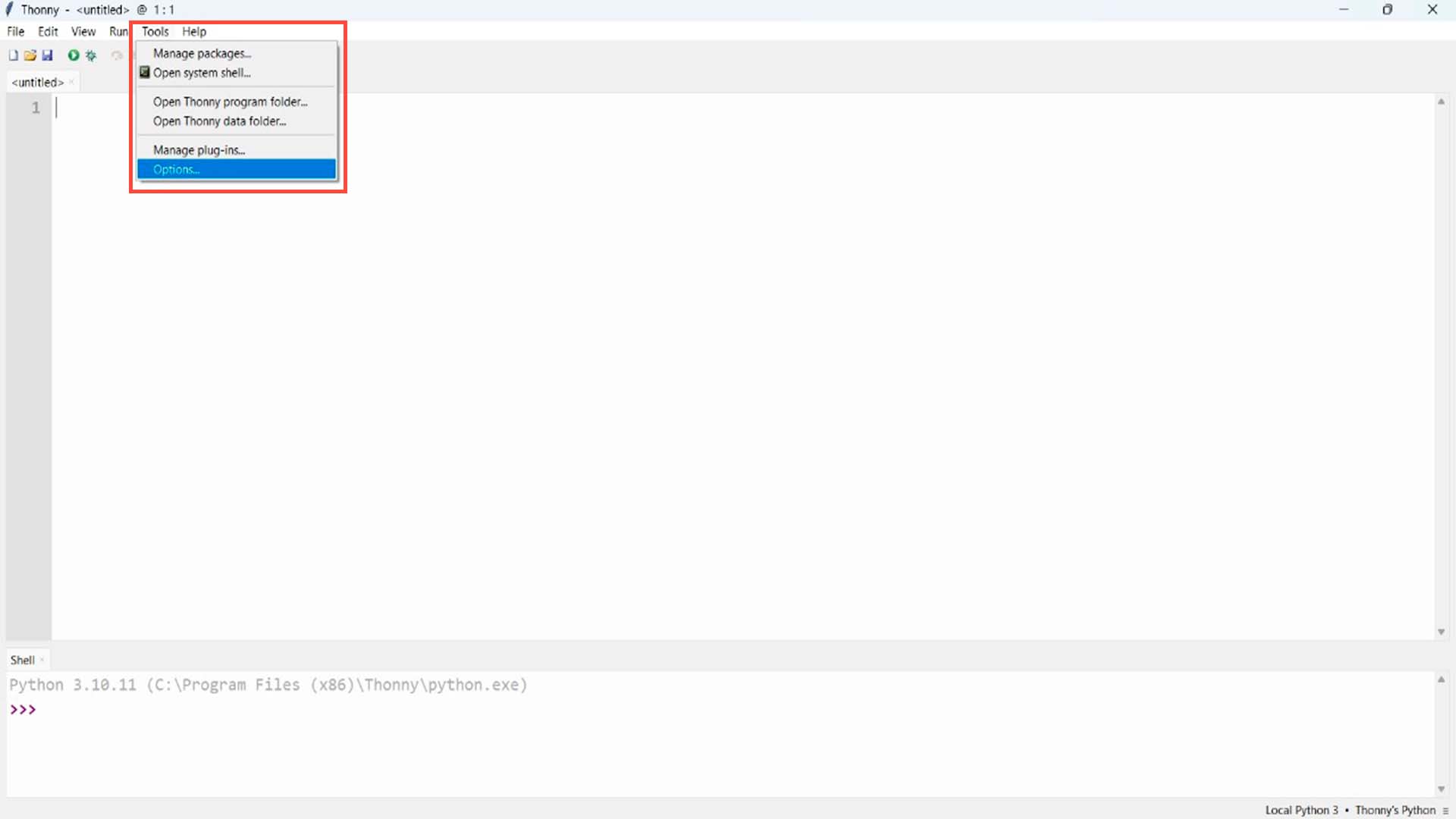
After completing the installation process we will be able to see the work area of the THONNY program. Where to start working and programming our microcontrollers, we first go to the TOOLS section, a window will appear and we choose OPTIONS.
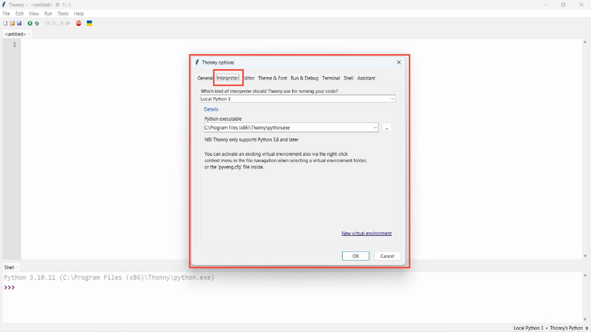
A window will appear with different options to choose from, in this case we go to the INTERPRETER section and click on it.
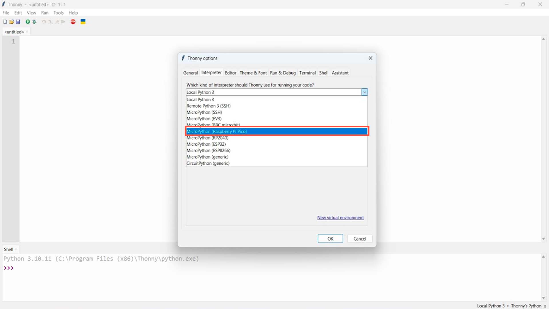
In the first option, we click on the drop-down list and look for the MICROPYTHON (RASPBERRY PI PICO) option and select it.
And for the second option, we select the option that says: TRY TO DETECT PORT AUTOMATICALLY and then we click on INSTALL OR UPDATE MICROPYTHON.
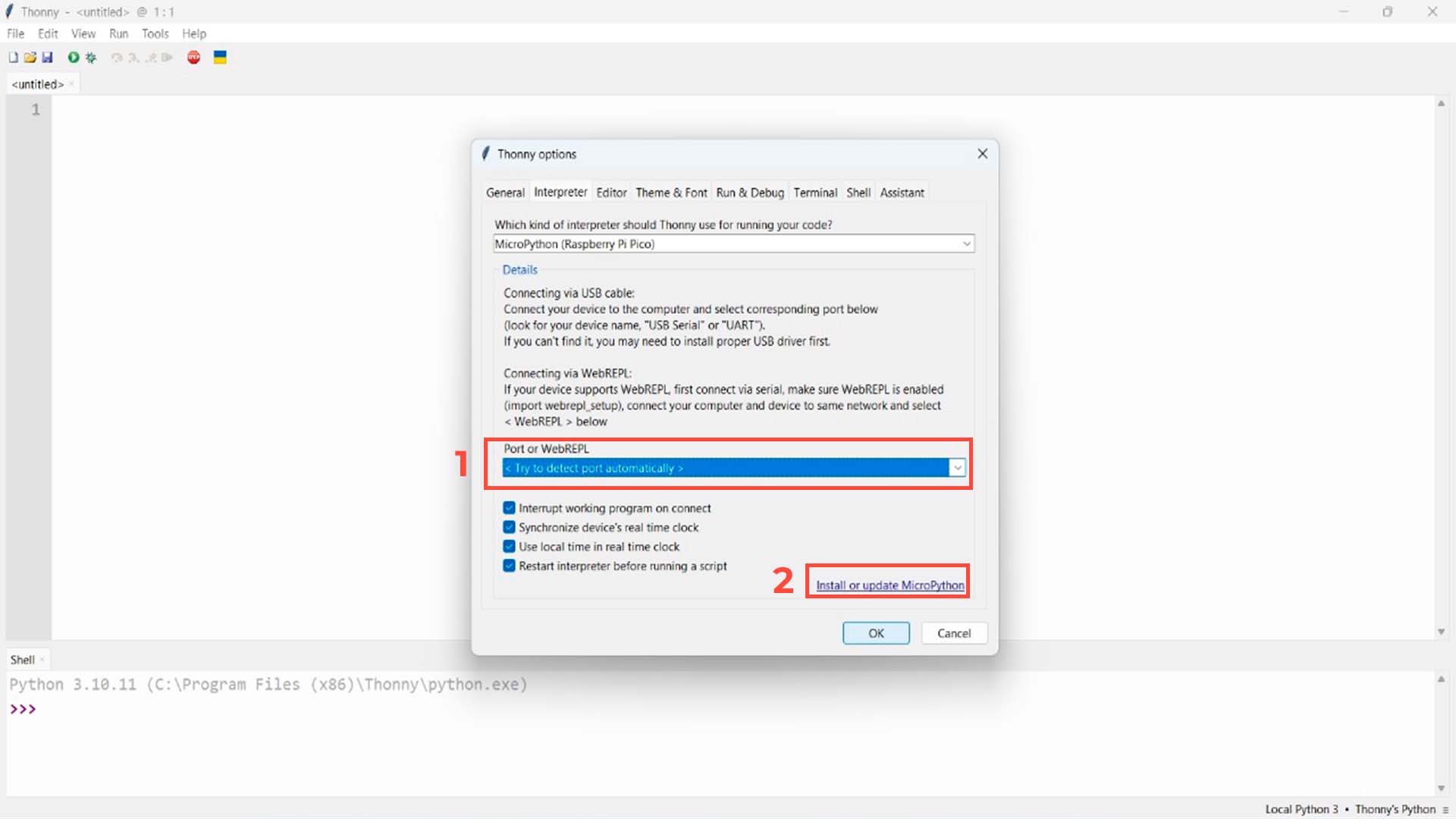
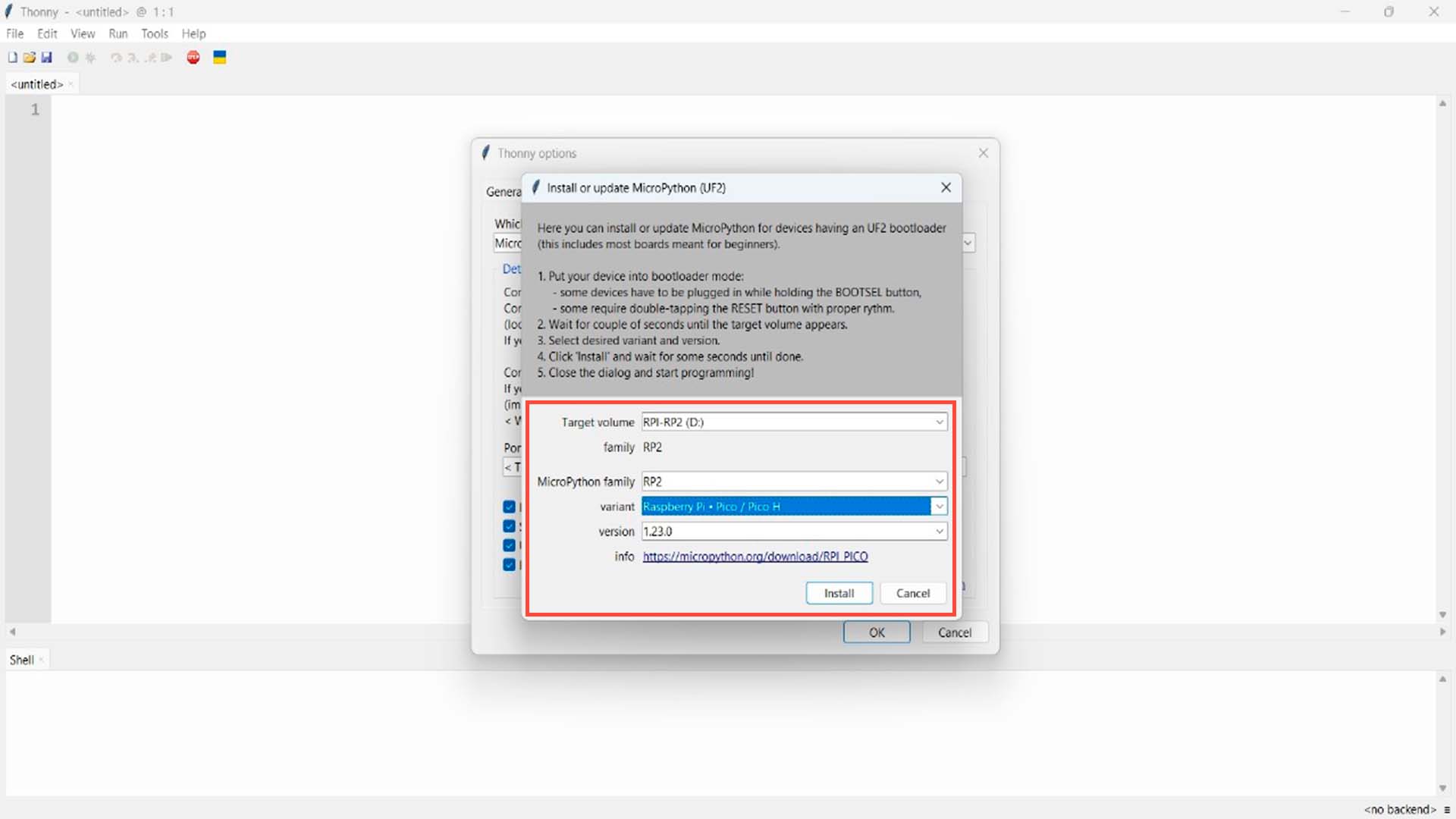
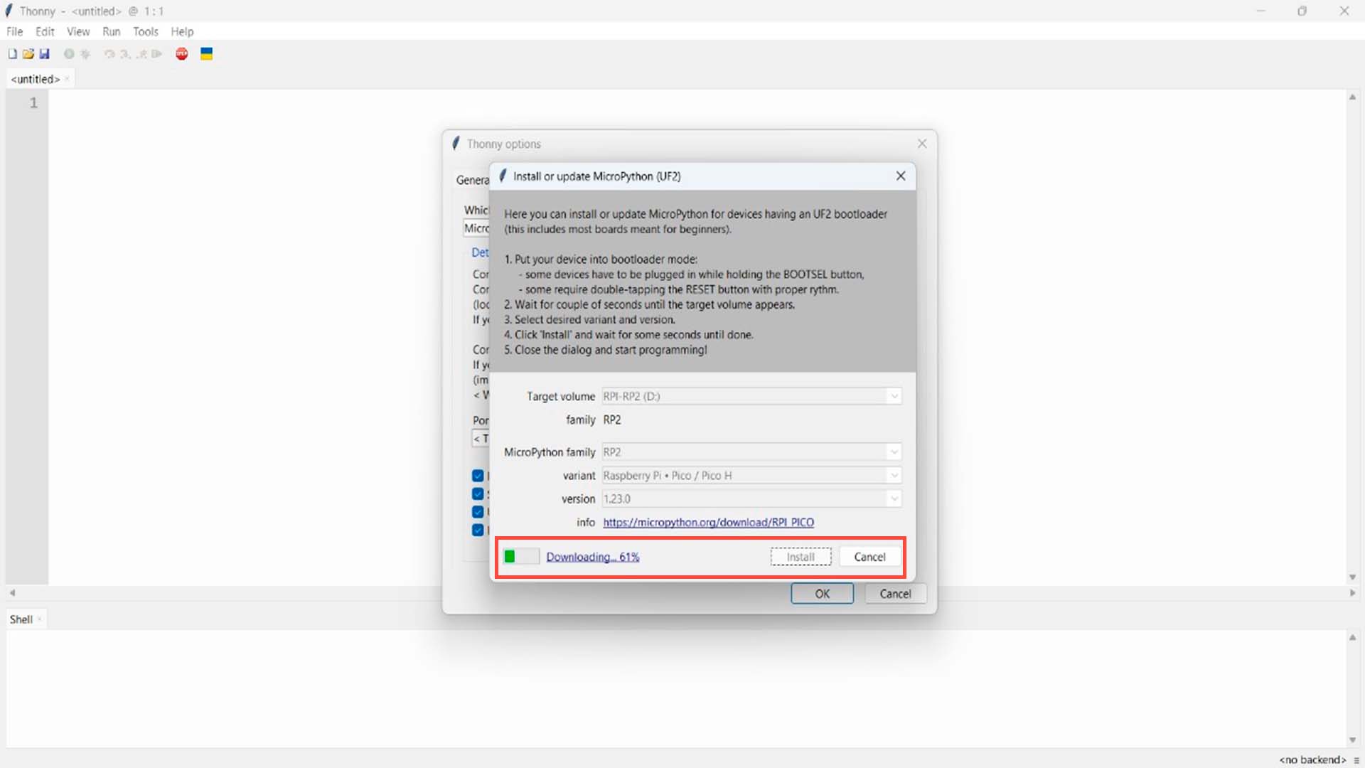
Here a new window will appear where we have to look for our microcontroller connected to our computer and in the VARIANT option, we look for the RASPBERRY PI + PICO / PICO H option and with everything selected, we click on INSTALL, where it will begin to install the program to start programming with THONNY.
BLINK A LED
To start programming in THONNY PYTHON, I will start programming a flasher with the LED that is connected to PIN 0 of the XIAO RP2040.
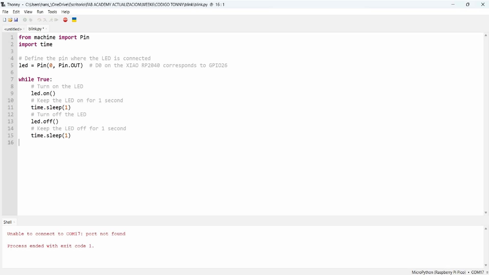
First we write the programming code to blink the LED, where we define the PIN where the LED is located and after that we program it to flash. Here is a screenshot of the programming code
Here I leave the code for THONNY - PYTHON
                                    from machine import Pin
                                    import time

                                    # Define the pin where the LED is connected
                                    led = Pin(0, Pin.OUT)  # D0 on the XIAO RP2040 corresponds to GPIO26

                                    while True:
                                        # Turn on the LED
                                        led.on()
                                        # Keep the LED on for 1 second
                                        time.sleep(1)
                                        # Turn off the LED
                                        led.off()
                                        # Keep the LED off for 1 second
                                        time.sleep(1)
We can see that the LED on pin P0 does BLINK according to the data mentioned in the program.
TURN ON RGB FROM XIAO RP2040
For our second programming at THONNY, I wanted to turn on the RGB LED that the XIAO RP2040 has. To do this, here I show the programming process that I carried out to be able to turn on the RGB in different colors.
To start programming and turning on the RGB LED of the XIAO RP2040. First we have to download the following PYTHON file that you can download by clicking on the following link, which will download a python file and you have to open it with THONNY.
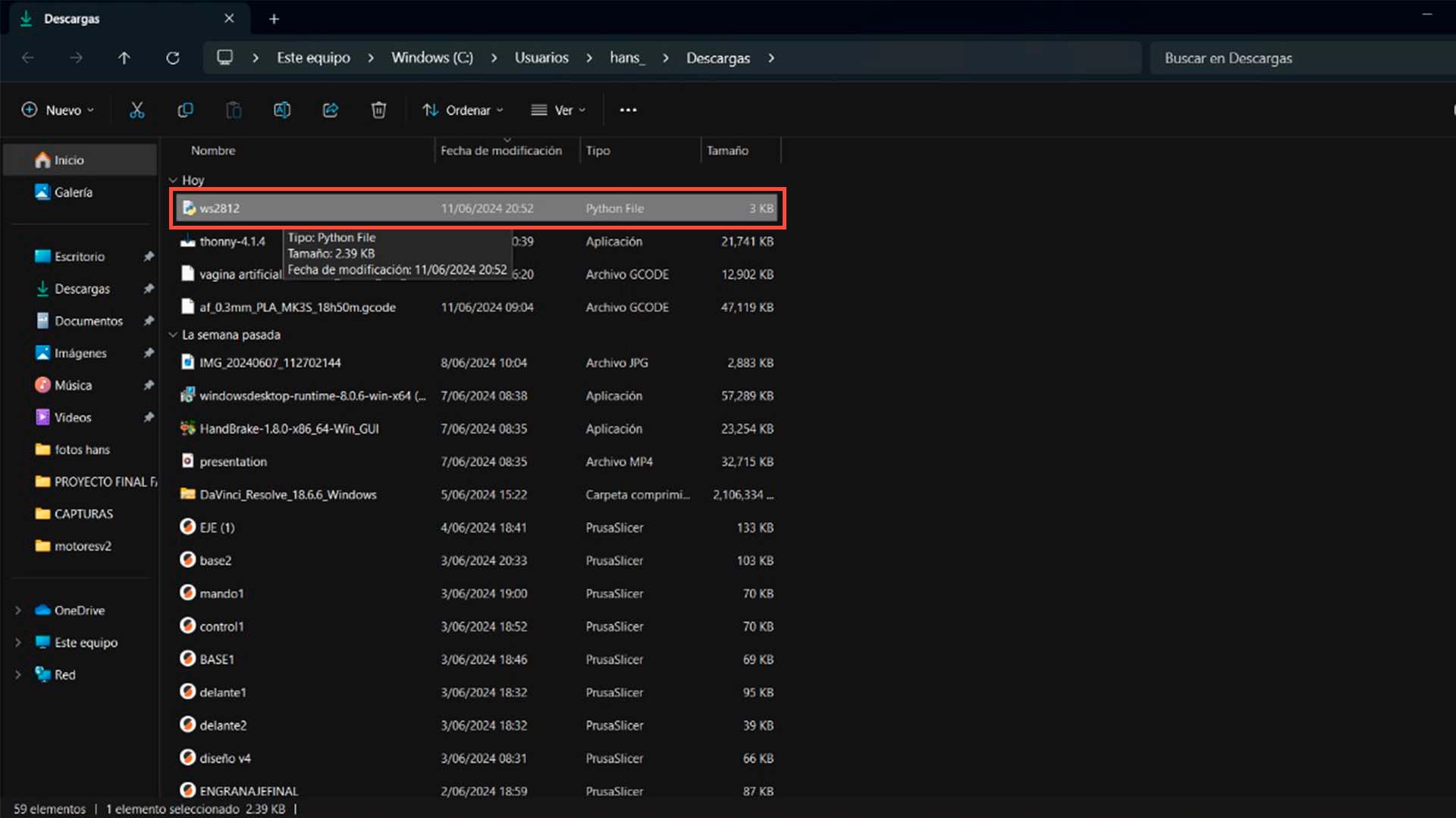
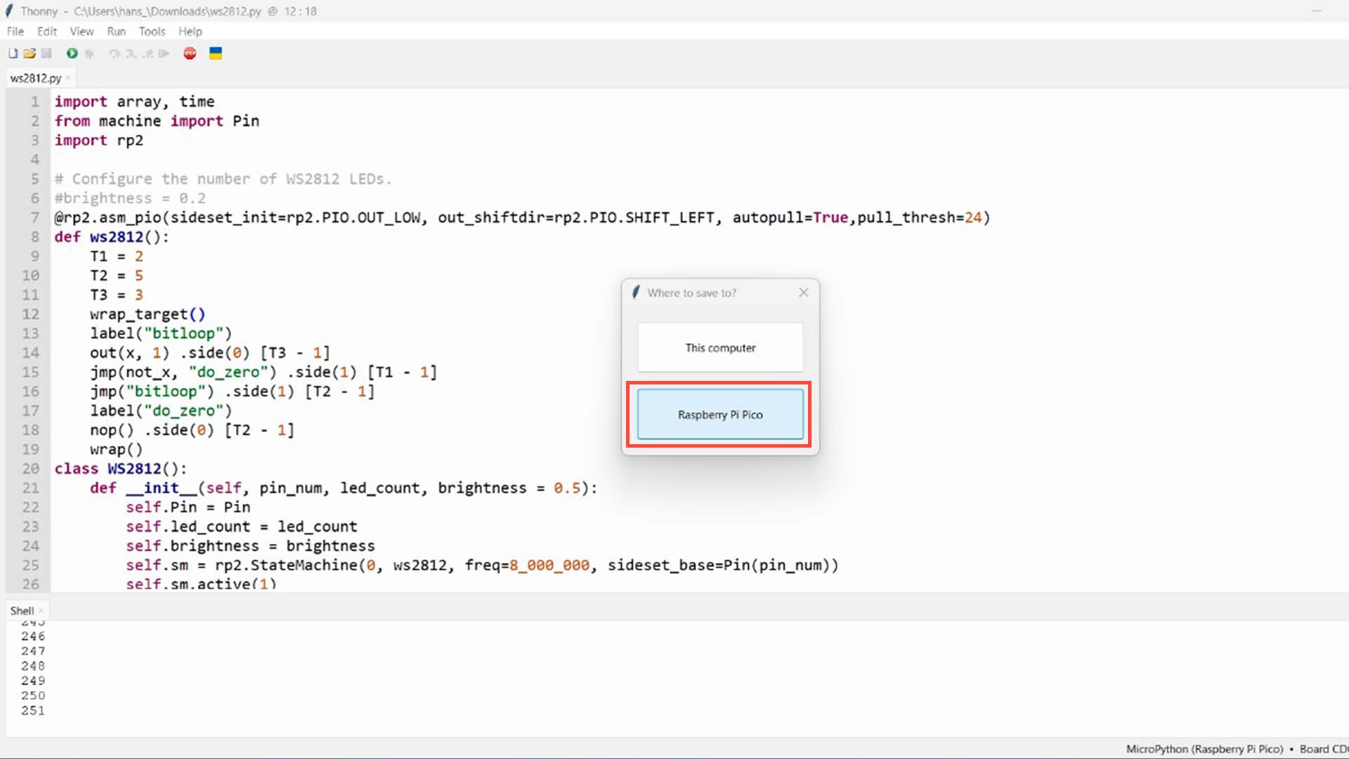
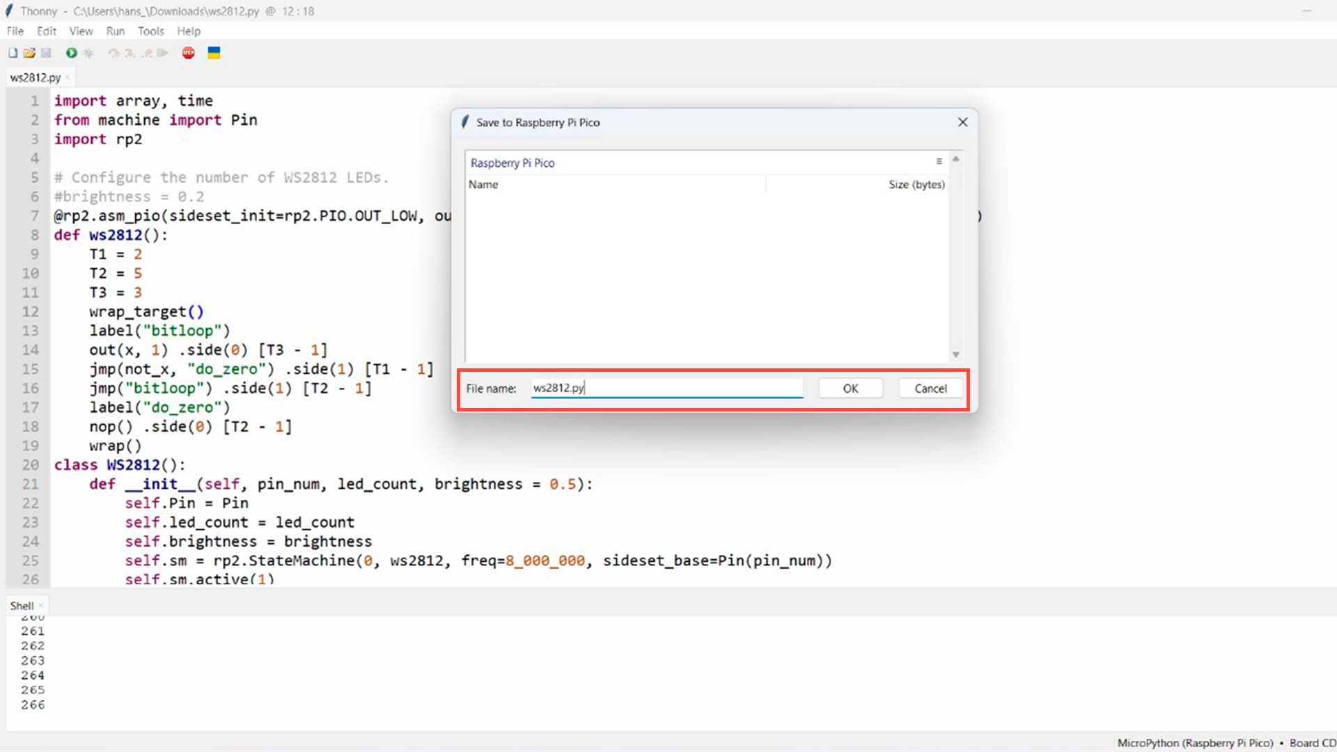
When opening with the program, what we have to do is go to save and choose the 2nd option of RASPBERRY PI PICO. This will cause a new window to appear, where we have to enter the same name of the library so that later when programming it can be linked and we can program.
After carrying out the previous process, we can start programming our RGB LED taking into account the previous saved file. Here I leave a screenshot of the code in the THONNY program and also the programming code.
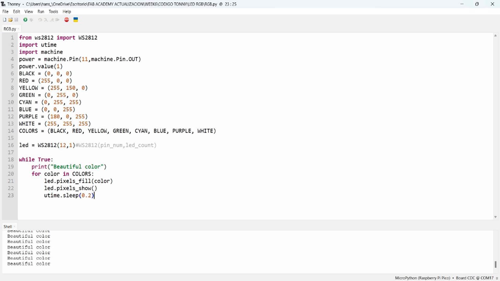
Here I leave the code for THONNY - PYTHON
                                    from ws2812 import WS2812
                                    import utime
                                    import machine
                                    power = machine.Pin(11,machine.Pin.OUT)
                                    power.value(1)
                                    BLACK = (0, 0, 0)
                                    RED = (255, 0, 0)
                                    YELLOW = (255, 150, 0)
                                    GREEN = (0, 255, 0)
                                    CYAN = (0, 255, 255)
                                    BLUE = (0, 0, 255)
                                    PURPLE = (180, 0, 255)
                                    WHITE = (255, 255, 255)
                                    COLORS = (BLACK, RED, YELLOW, GREEN, CYAN, BLUE, PURPLE, WHITE)

                                    led = WS2812(12,1)#WS2812(pin_num,led_count)

                                    while True:
                                        print("Beautiful color")
                                        for color in COLORS:
                                            led.pixels_fill(color)
                                            led.pixels_show()
                                            utime.sleep(0.2)
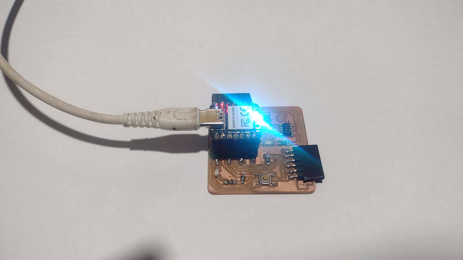
Here we can see when the RGB LED of the XIAO RP2040 turns on and changes colors.
INPUT
BUTTON PROGRAMMING
On the other hand, similar to what we did with the ARDUINO IDE, I will also try programming the switch that we have in the QUENTORRES with THONNY. Where when you press the switch, the 2 LEDs that we have on the board will light up. Here the process and result.
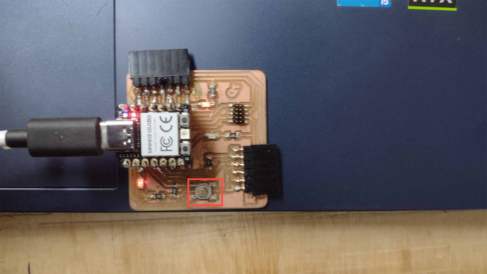
To program the switch, we first have to define the LEDs that we want to turn on and then define the PIN where the SWITCH is located, and from there give it the functions we want, in this case, I want to achieve that when pressing the switch, the 2 LEDs they light up. Here I leave the programming code in THONNY and also a video of the result.
Here I leave the code for THONNY - PYTHON
                                    from machine import Pin
                                    import time

                                    # Define the pins where the LEDs are connected
                                    led1 = Pin(26, Pin.OUT)
                                    led2 = Pin(1, Pin.OUT)

                                    # Define the pin where the button is connected
                                    button = Pin(27, Pin.IN, Pin.PULL_UP)

                                    # Initial state of the LEDs
                                    led_state = False

                                    # Function to toggle the state of the LEDs
                                    def toggle_leds(state):
                                        if state:
                                            led1.on()
                                            led2.on()
                                        else:
                                            led1.off()
                                            led2.off()

                                    # Previous state of the button
                                    last_button_state = button.value()

                                    while True:
                                        current_button_state = button.value()

                                        # Detect if the button has been pressed (transition from high to low)
                                        if last_button_state == 1 and current_button_state == 0:
                                            # Change the state of the LEDs
                                            led_state = not led_state
                                            toggle_leds(led_state)
                                            print("Button pressed, LEDs on" if led_state else "Button pressed, LEDs off")
                                            # Wait to avoid button bouncing
                                            time.sleep(0.2)

                                        # Update the previous state of the button
                                        last_button_state = current_button_state

                                        # Small delay to reduce CPU load
                                        time.sleep(0.01)
Here is a video of the result programming the switch with THONNY.
MOTION DISTANCE + THONNY
Likewise, I also wanted to program the motion sensor with the THONNY program similar to what we did in the ARDUINO IDE program. To do this, we connect the sensor to PIN 1 of the XIAO RP2040 of the QUENTORRES board and begin programming.
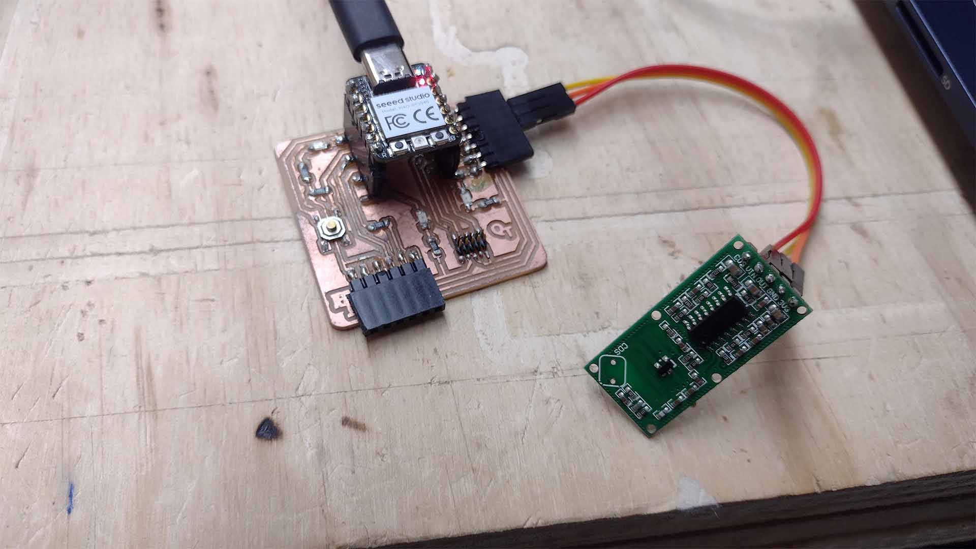
To program the motion sensor, I carried out basic programming so that the sensor can send a signal via serial when it detects movement and when it does not. Here the code and the result.
Here I leave the code for THONNY - PYTHON
                                    from machine import Pin
                                    import time

                                    # Define the pin where the motion sensor is connected
                                    motion_sensor = Pin(1, Pin.IN)

                                    while True:
                                        if motion_sensor.value() == 1:
                                            print("Motion detected!")
                                        else:
                                            print("No motion")

                                        # Wait 0.5 seconds before reading the sensor again
                                        time.sleep(0.5)
In the video we can see that on the program screen the sensor sends messages of "MOTION DETECTED" and "NO MOTION" when detecting whether or not there is movement.
OUTPUT
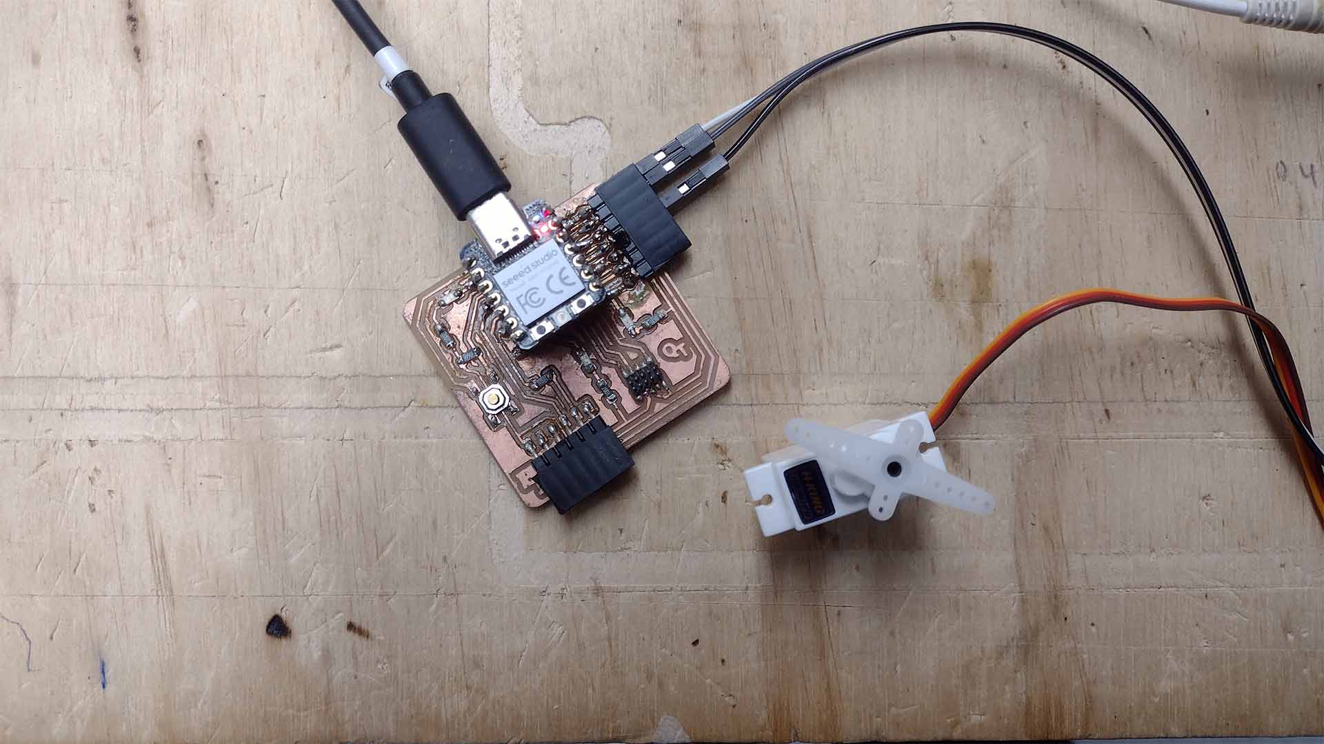
SERVOMOTOR + THONNY
Finally, as OUTPUT programming, I will work with the servomotor, similar to what I worked with ARDUINO IDE, I will try to program it with THONNY. So for this occasion I connected it to PIN 3 of the XIAO RP2040 and started working.
Here I leave the code for THONNY - PYTHON
                                    from machine import Pin, PWM
                                    import time

                                    # Define the pin where the servo motor is connected
                                    servo_pin = Pin(3)
                                    servo = PWM(servo_pin)

                                    # Set the PWM frequency to 50 Hz (typical for servo motors)
                                    servo.freq(50)

                                    def set_servo_angle(servo, angle):
                                        # Convert the angle into a duty cycle
                                        # Typical duty cycle range is 2.5% (0 degrees) to 12.5% (180 degrees)
                                        min_duty = 1000  # approximate value for 0 degrees
                                        max_duty = 9000  # approximate value for 180 degrees
                                        duty = min_duty + (max_duty - min_duty) * angle // 180
                                        servo.duty_u16(duty)

                                    # Example of how to move the servo motor
                                    try:
                                        while True:
                                            # Move to 0 degrees
                                            set_servo_angle(servo, 0)
                                            time.sleep(1)
                                            # Move to 90 degrees
                                            set_servo_angle(servo, 90)
                                            time.sleep(1)
                                            # Move to 180 degrees
                                            set_servo_angle(servo, 180)
                                            time.sleep(1)
                                    except KeyboardInterrupt:
                                        # Turn off the PWM when the program is interrupted
                                        servo.deinit()
In the video we can see that it is also possible to program with THONNY, here is the result.
FILES
Here you can download all the files that I have made for the following assignment: