This week's assignment was:
- Test the design rules for your 3D printer(s)
- Design and 3D print an object (small, few cm3, limited by printer time) that could not be made subtractively.
- 3D scan an object (and optionally print it)
ORGANIZATION
Here I show how I organized myself for this week.
| Wednesday 21th: | Fab Academy classes |
|---|---|
| Thursday 22th: | 3D printing of class models for group order. Documentation No. 1 and commit |
| Friday 23th: | Finish the group assignment. First design for individual order and printing test. |
| Saturday 24th: | Enter OPEN GLOBAL TIME. Final design of the individual order and 3D printing of it. |
| Sunday: 25th: | Documentation of everything done and commit |
| Monday 26th: | AScan an object for individual design and documentation. |
| Tuesday 27th: | Review of all documentation and last commit for this week. |
GROUP ASSIGNMENT
Here I leave the link to go to the group assignments page.
Clic here to visit the WEEK 5 GROUP ASSIGNMENT PAGE
TEST THE DESIGN RULES
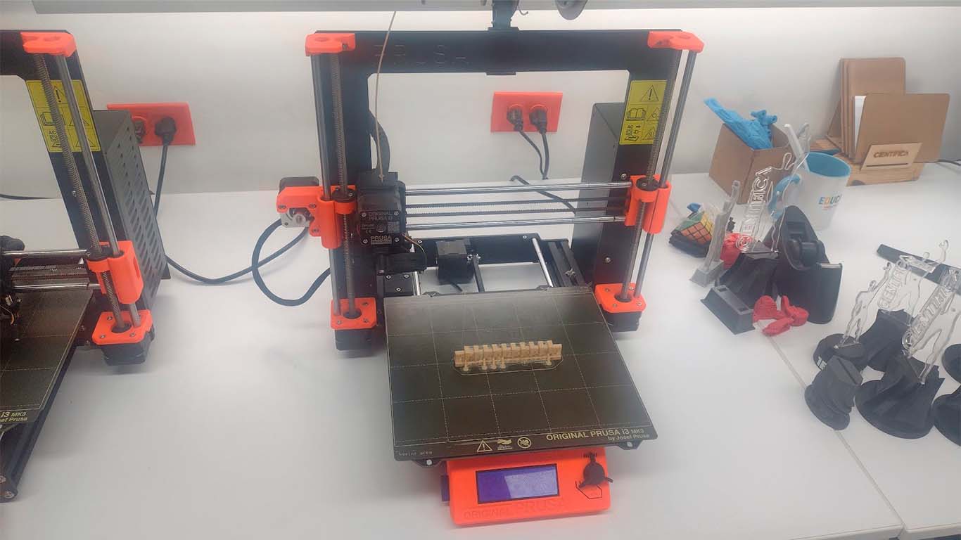
3D PRINTER
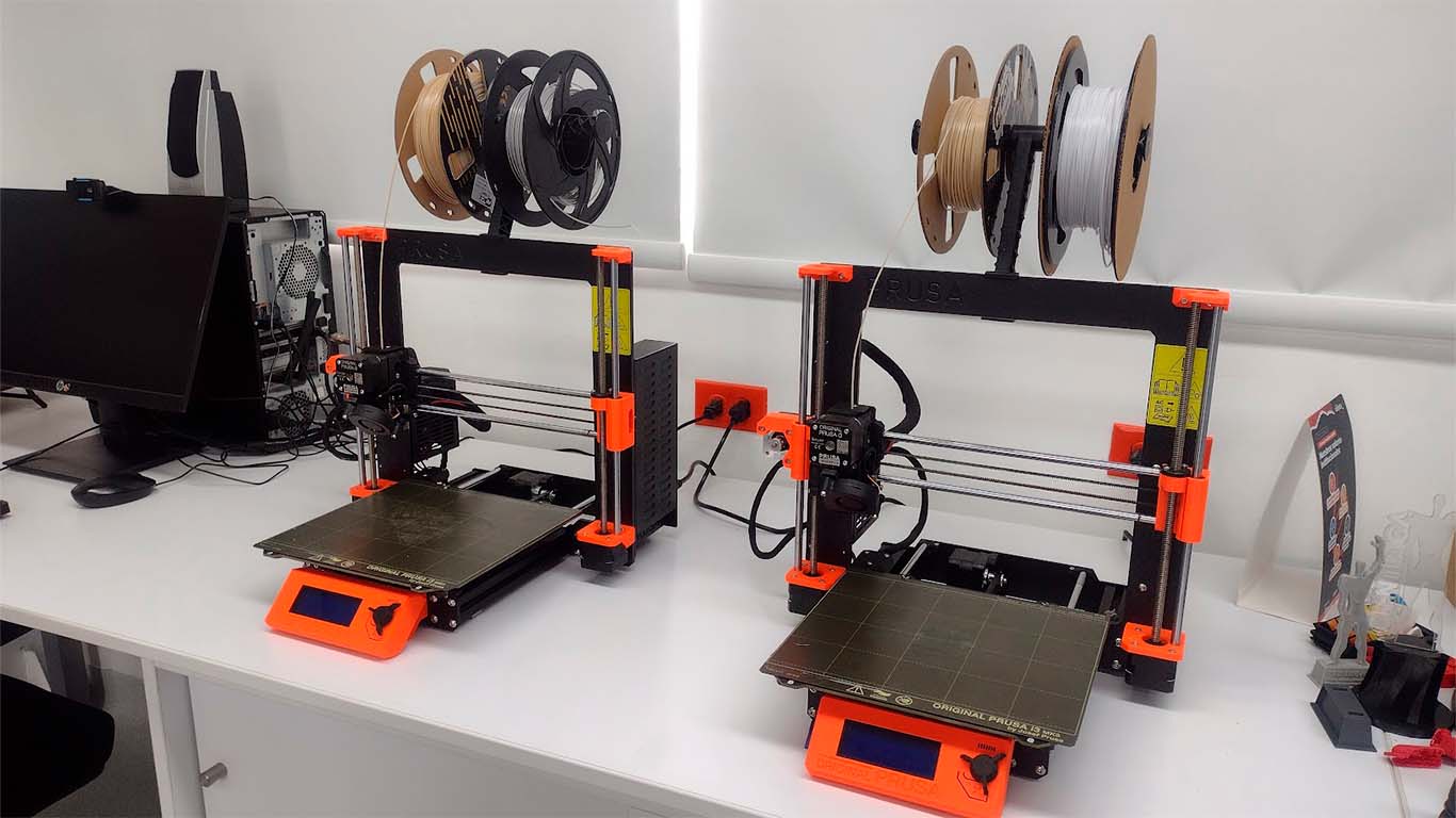
The 3D printers that we have at the Cientifica del Sur University are the PRUSA I3 MK3 that have the following technical specifications:
| PRINT VOLUME: | 11,025 cm3 (25 x 21 x 21 cm o 9,84 x 8,3 x 8,3 in) |
|---|---|
| ENERGY CONSUMPTION: | PLA Settings: 80W / ABS Settings: 120W |
| SUPPORTED MATERIALS: | PLA, ABS, PET, HIPS, Flex PP, Ninjaflex, Laywood, Laybrick, Nylon, Bamboofill, Bronzefill, ASA, T-Glase, |
| PRINTER DIMENSIONS: | 7 kg, 55 x 40 x 50 cm; 21.6 x 15.7 x 19.6 in |
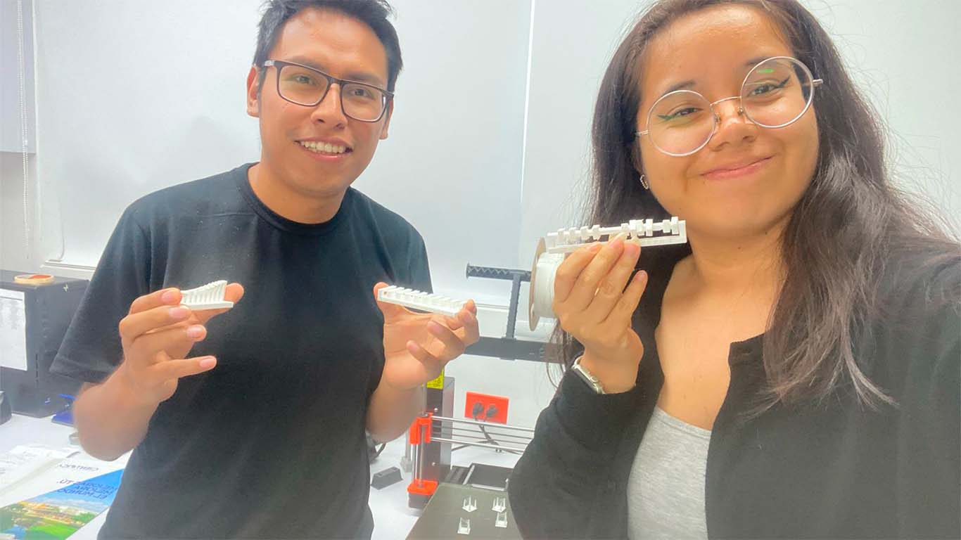
Together with my friend Maryori we decided to do all the tests that Neil proposed and that we can find on the assignment page and see if both printers have the capacity to perform them. Once downloaded, we proceed to perform them without supports and see if all the tests can be carried out by the PRUSA I3.
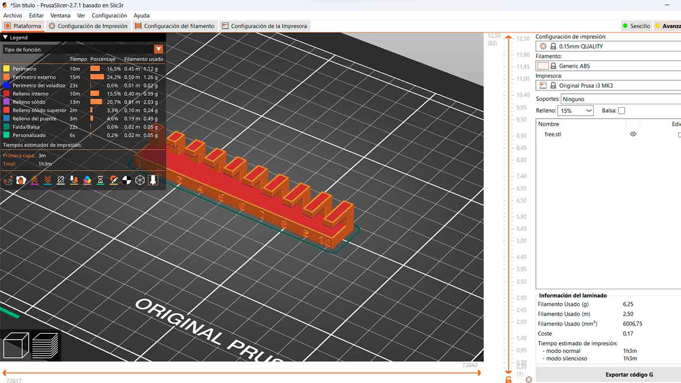
For the tests I will show the steps that are carried out in the PRUSA SLICER software and how we obtain the result of each test.
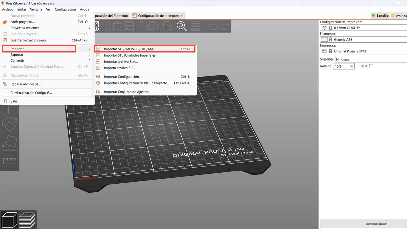
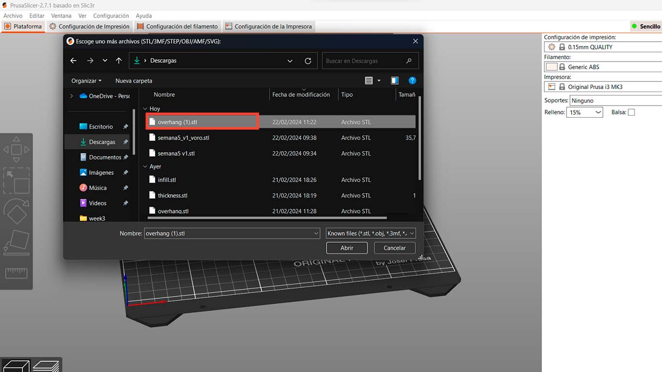
First, we open the PRUSA SLICER program and go to "FILES" then "IMPORT" and choose "IMPORT STL" which in this case we have all the references in this extension. We will repeat this procedure in all the tests for this group assignment. On the other hand, for the following tests we use the PLA FILAMENT with a plate temperature of 60° and a nozzle temperature of 250°
TEST SUPPORT
The next 2 tests are about seeing the support generated by the program itself to be able to carry out the 3D modeling that we have. Here I show the 3D in the software with the settings mentioned above and its result with the 3D printer.
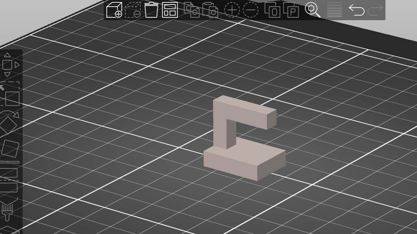
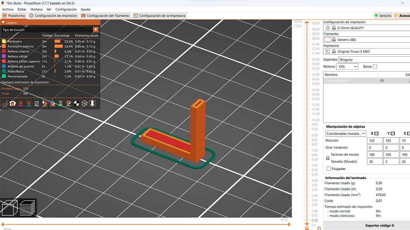
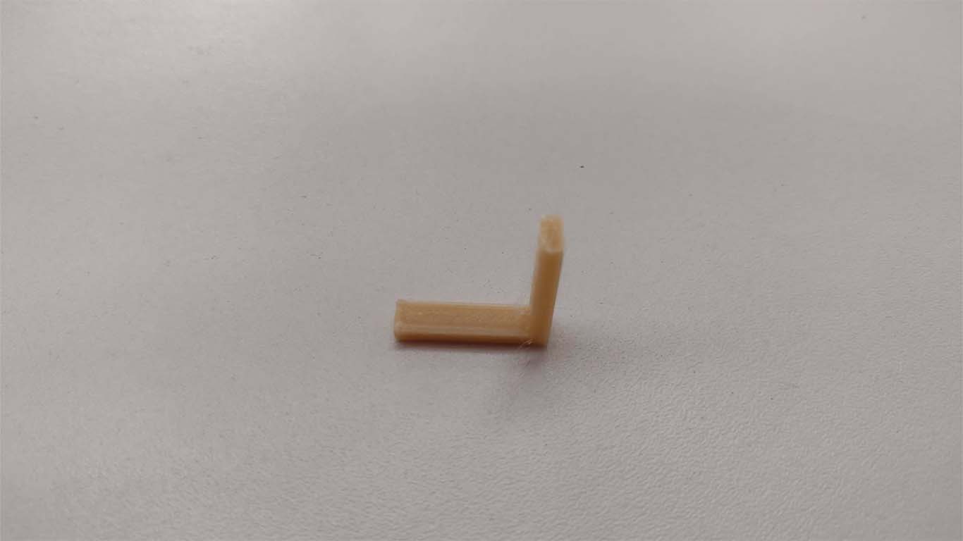
TEST OVERHANG
The following test presents an inverted L-shaped modeling where supports are generated that can be generated in the software we use to be able to print it in 3D. Here I show images of the generated supports and the printed result.
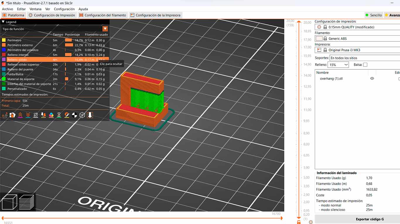
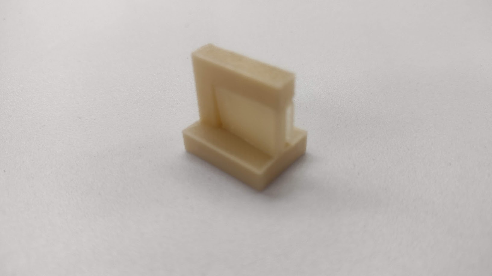
CONCLUSION: In the next test, the 3D printer was able to perform modeling normally. By presenting support, the model could be made without problems and the machine could work normally.
TEST 1 CLEARANCE
The following test is complex because the modeling requires that the rectangular volumes be able to move and have the appropriate separation to be able to remove the supports and obtain the result. We were able to clean it and see that the 3D printer was able to do it.
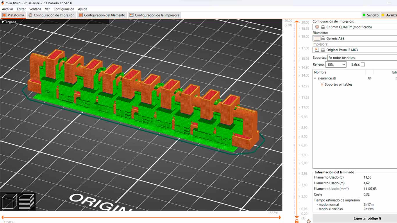
CONCLUSION: In the next test, the 3D printer was able to make a print with a lot of "spider" or "excess filament" as can be seen in the third and fourth photo and where we changed the supports unlike what it shows us in the FAB ACADEMY. Here we saw that the printer retraction was not correct. So with the help of our instructor and some research on the internet, they recommended us to perform THE RETRACTION TEST, this serves to eliminate these "cobwebs" that 3D prints have.
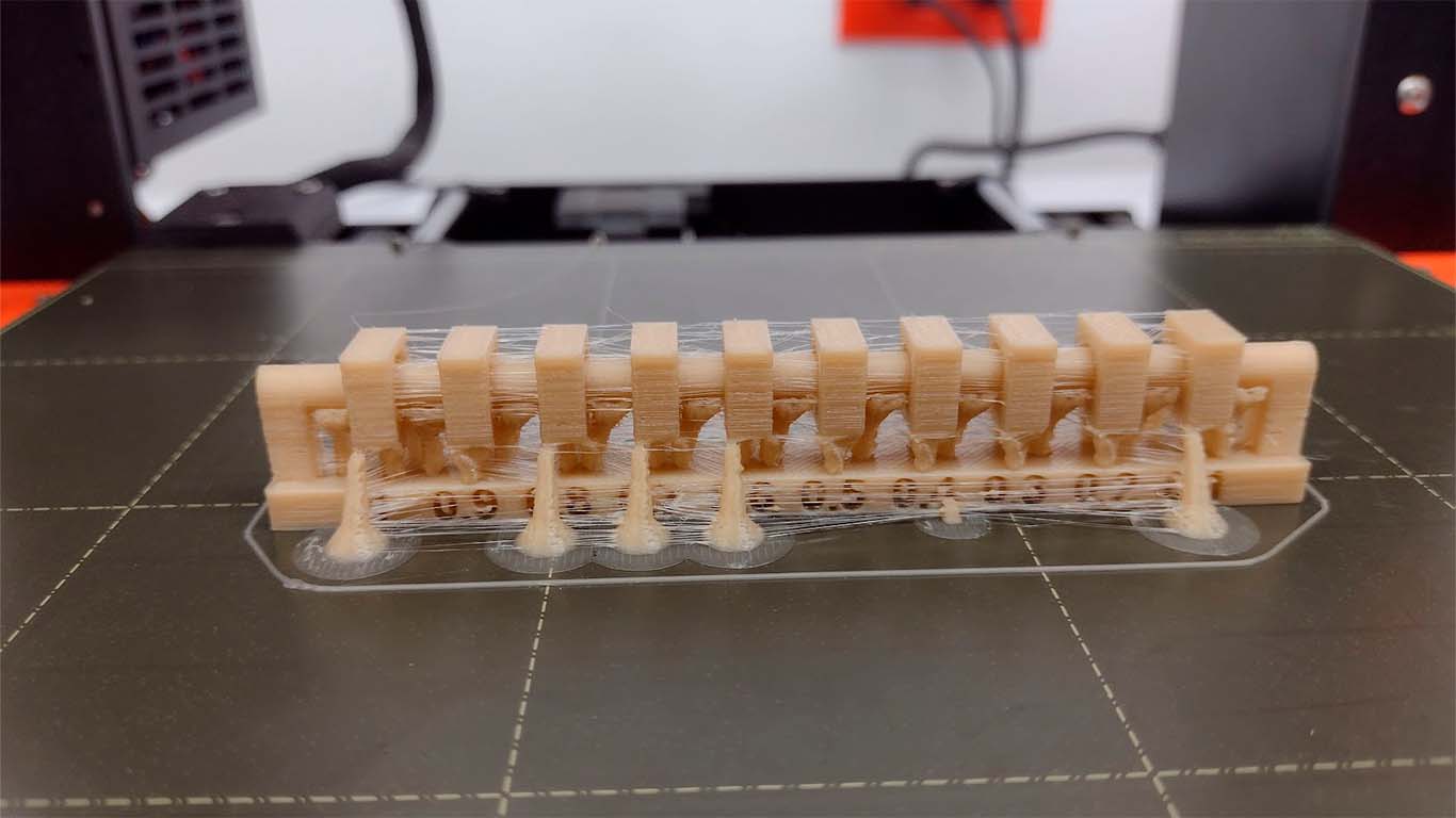
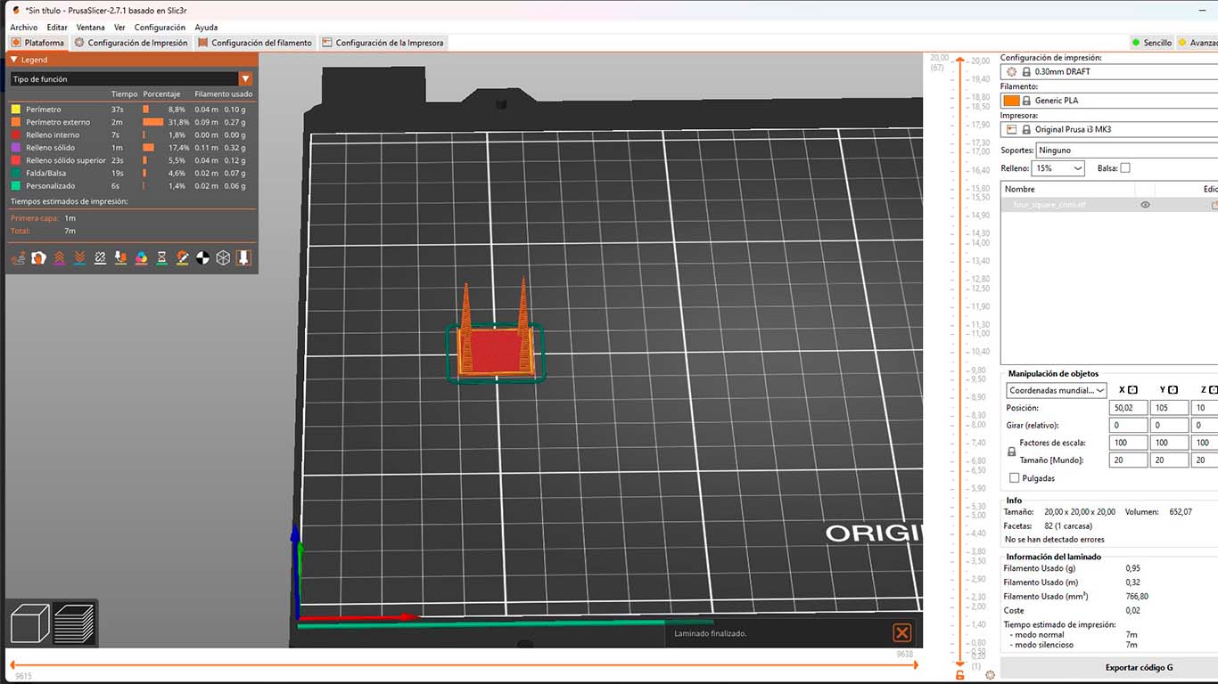
RETRACTION TEST
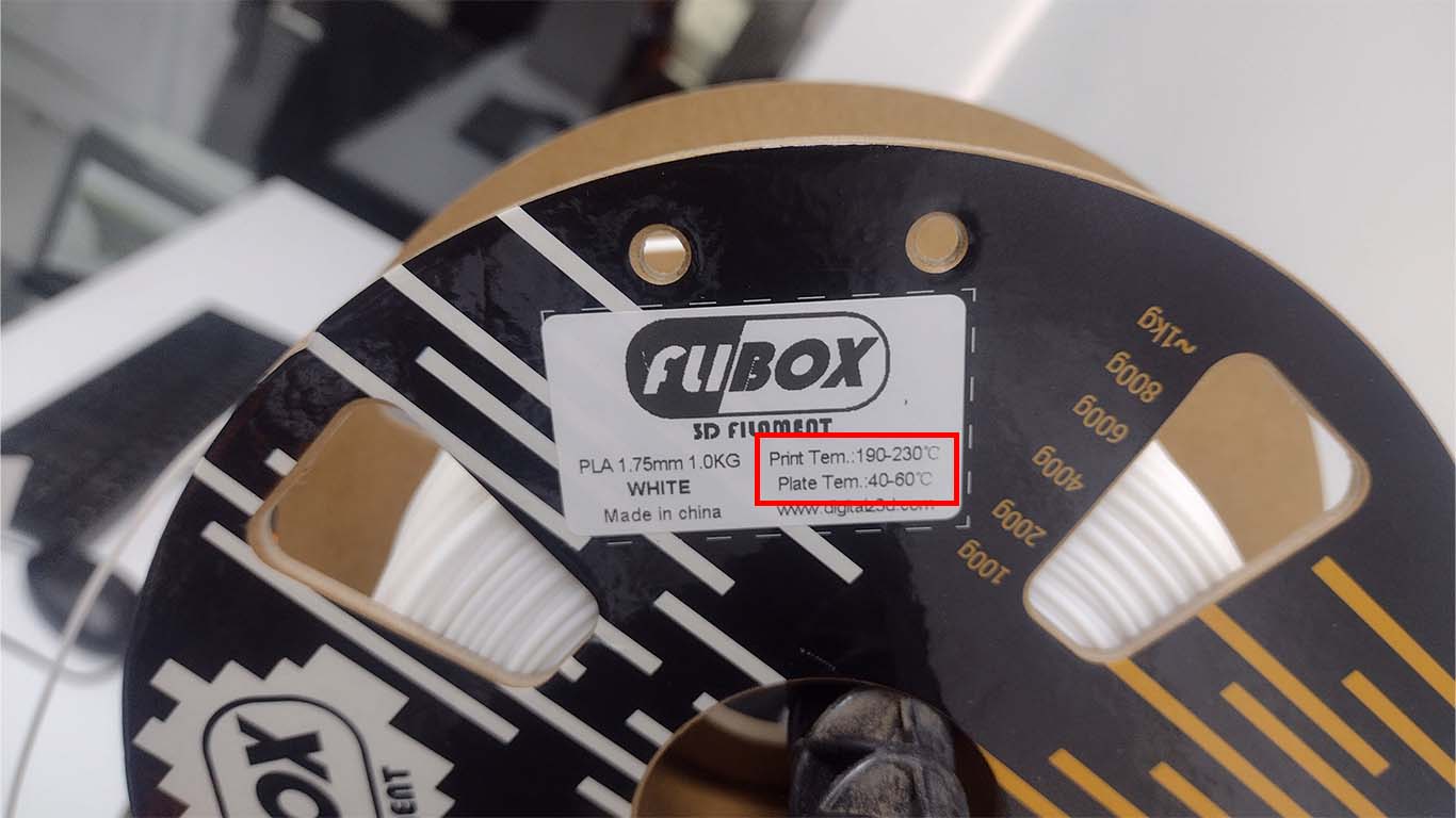
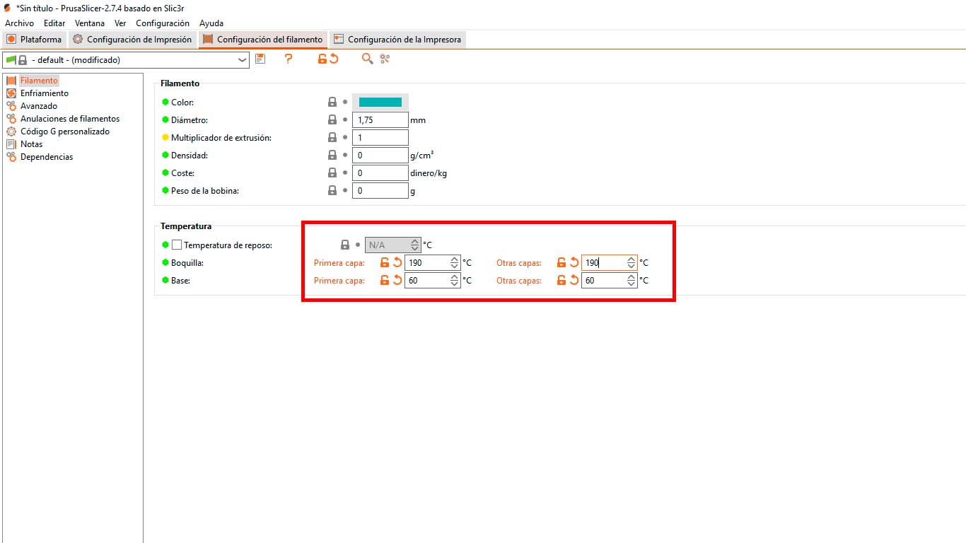
First we reviewed the technical specifications of the filament with which we were going to do the test and first we will use the maximum temperature in both the extruder and the bed of the 3D printer.
We then change the settings in the PRUSASLICER with the temperatures recommended by the filament manufacturer.
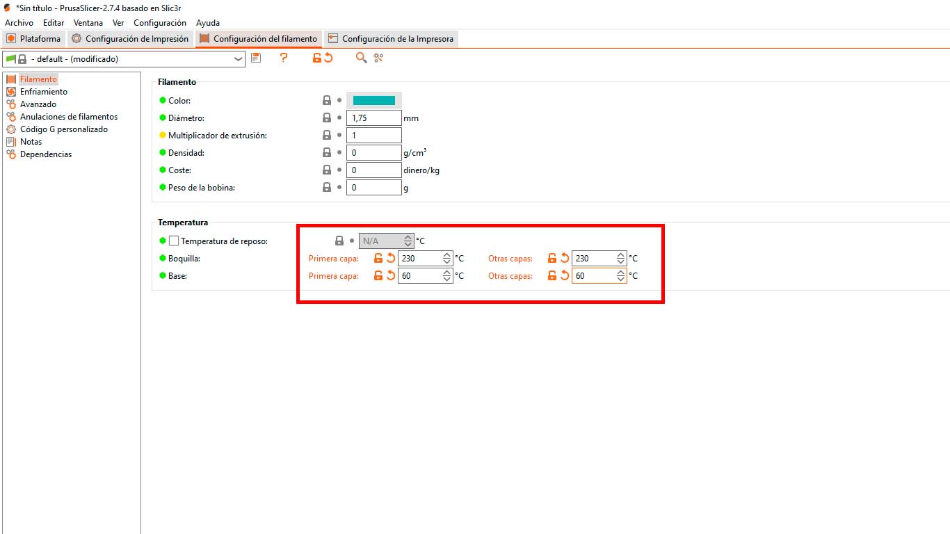
And here we were going to start with a RETRACTION LENGTH of 0.4; 0.8; 1.2 to know which of these values we have fewer cobwebs
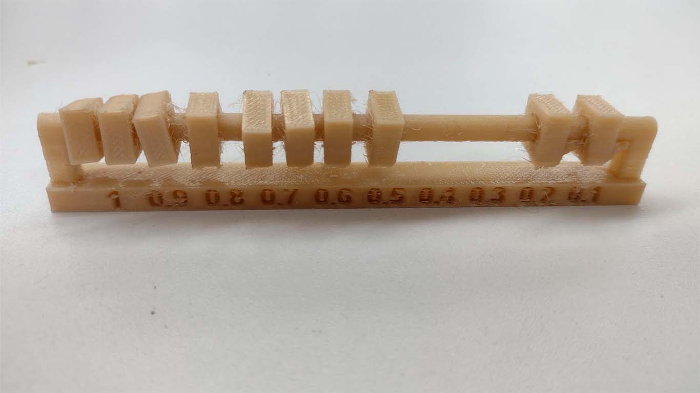
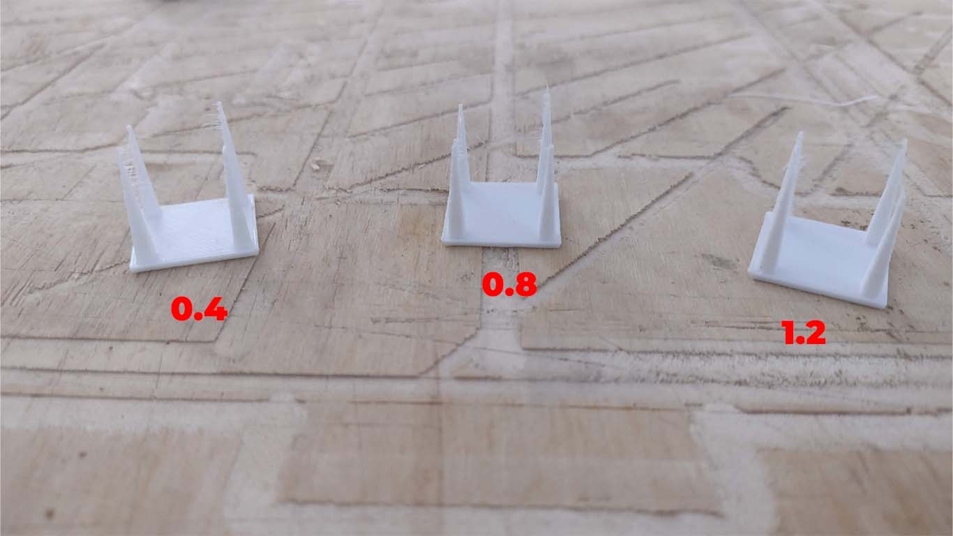
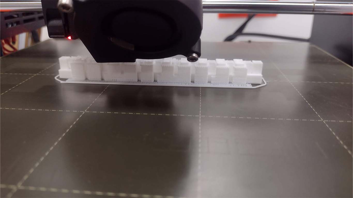
After configuring all the PRUSASLICER, we sent it to print and we didn't really understand what was happening, everyone had these cobwebs in the modeling, we thought that the configuration or the 3D printer itself was wrong. Here are some photographs of the tests and we add some more measurements.
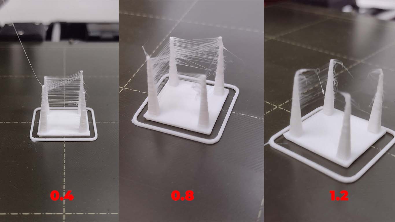
Here is a screenshot of all the retraction tests and only 1 came out more or less, which has a value of 0.4 but still had the same retraction problems.
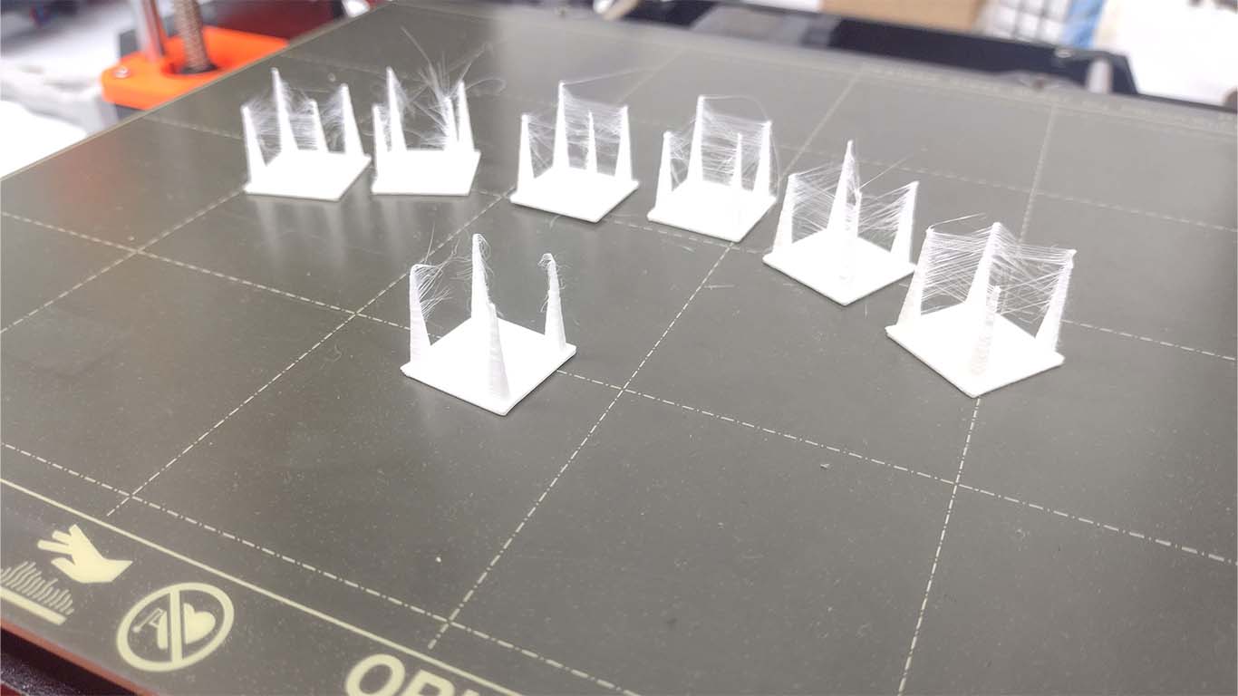
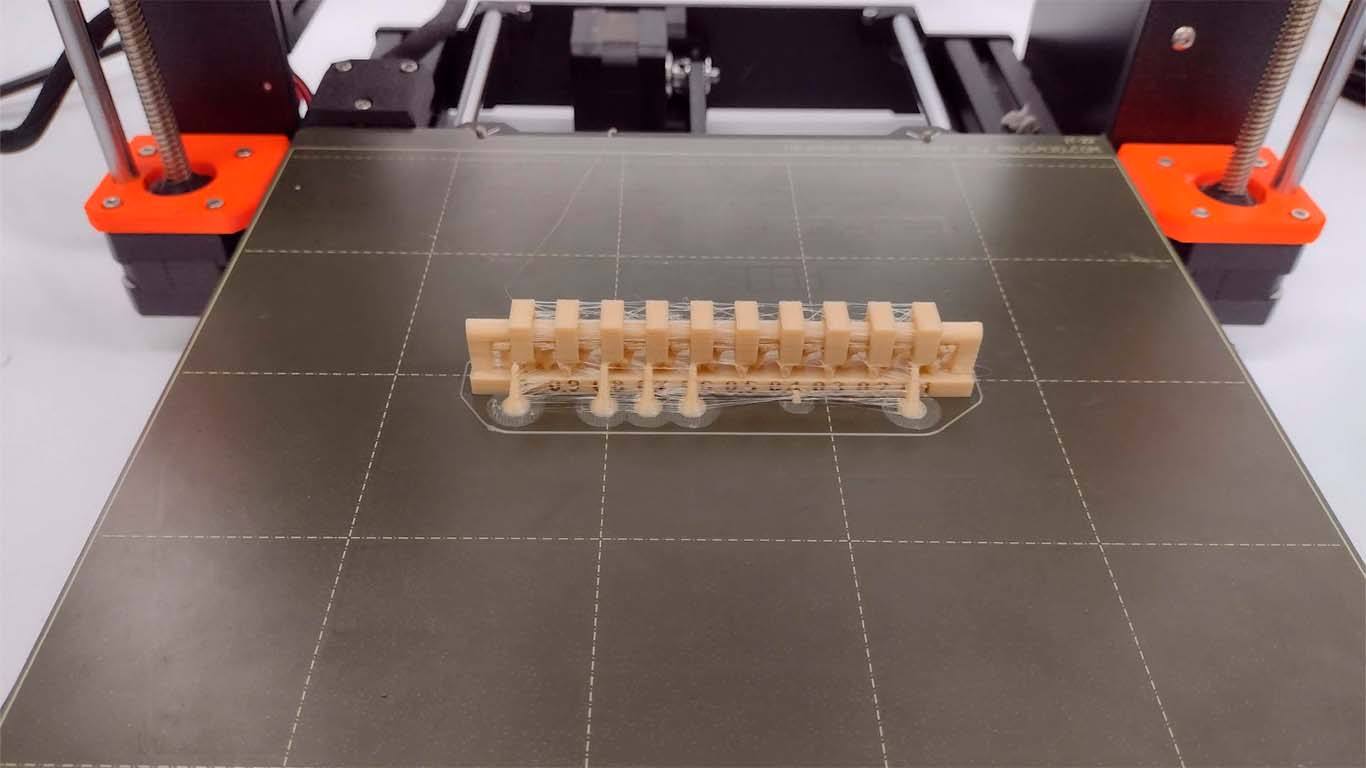
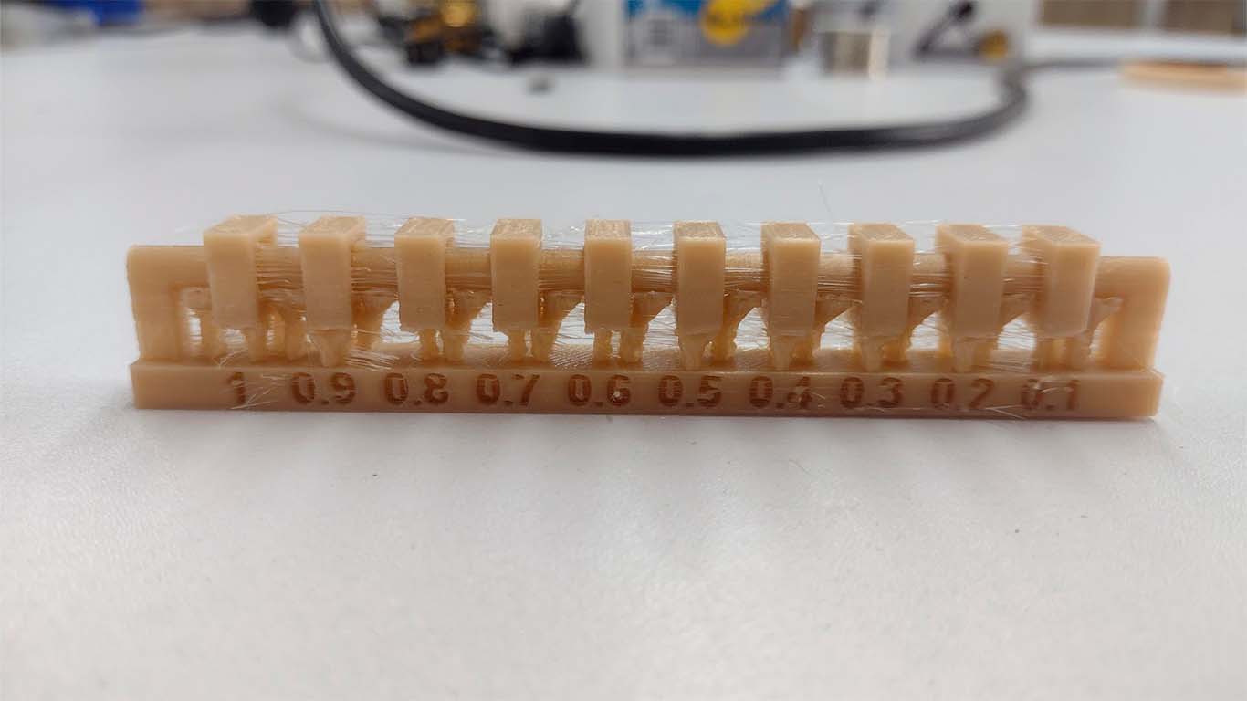
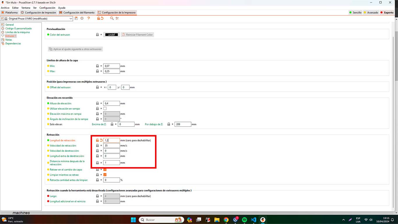
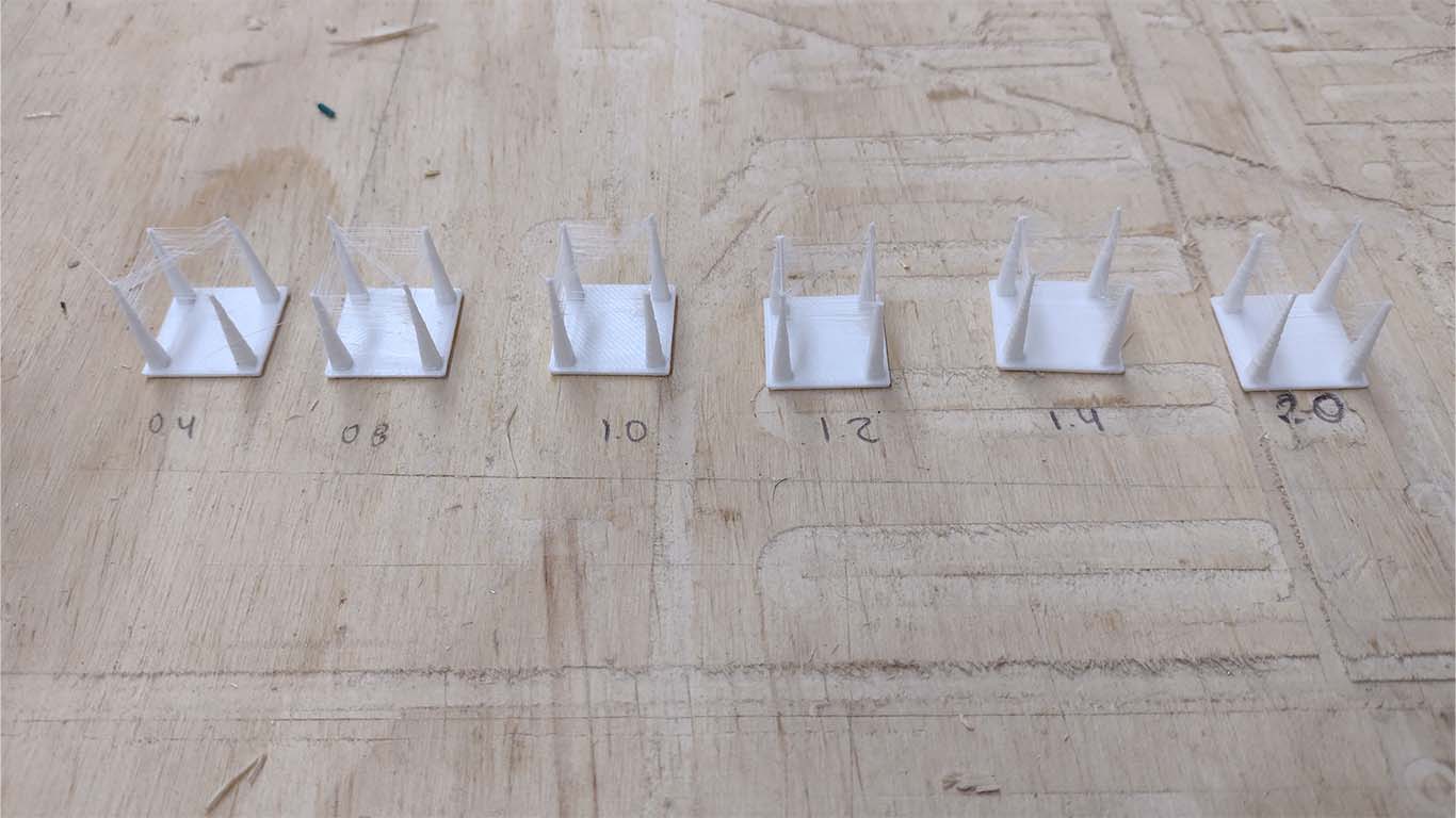
After doing a little more research and together with my friend Maryori, who has more knowledge in 3D printing and is here to solve these problems because she knows a lot. We decided to lower the extruder temperature to the minimum requested by the filament manufacturer. So now we will work with 190° and we still did the retraction tests at 0.4; 0.8 and 1.2 to see the results.
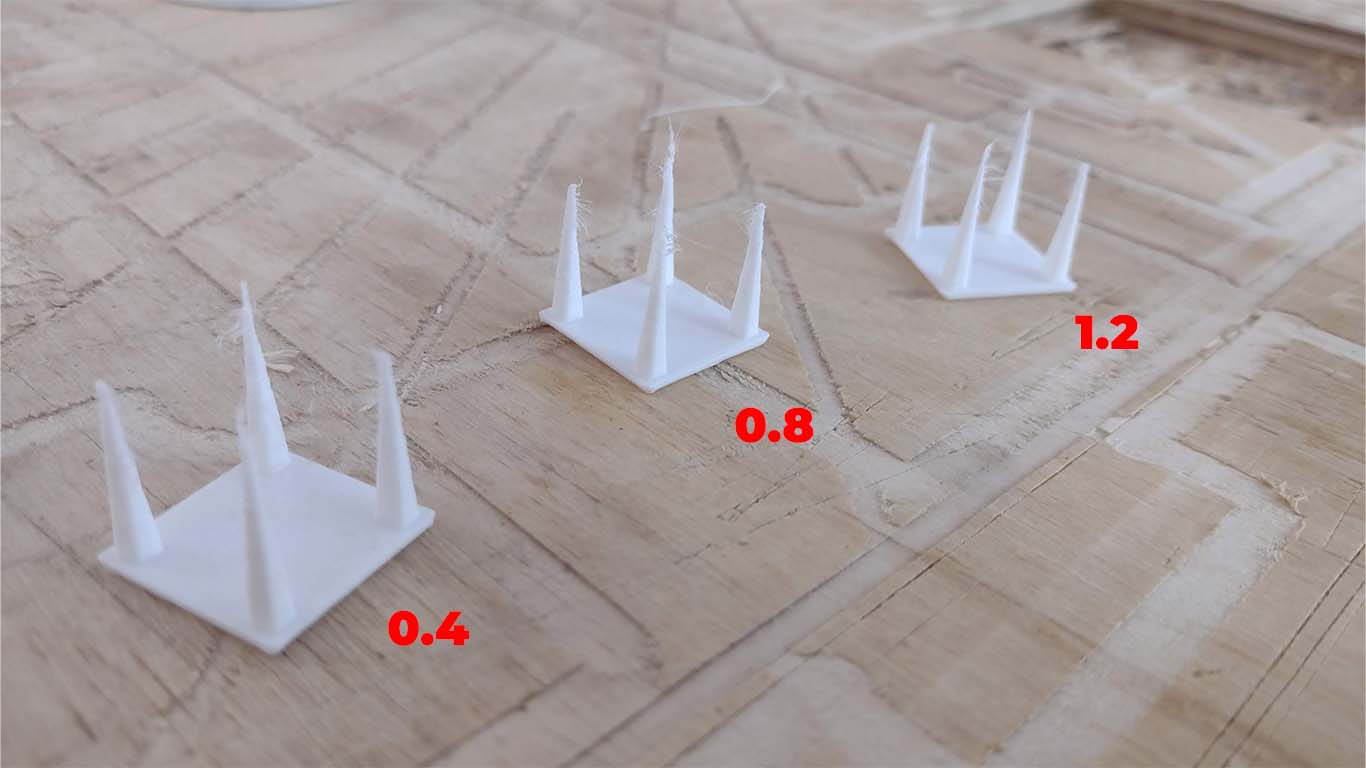
CONCLUSIONS: Now, the retraction test came out better, with fewer cobwebs and cleaner. Drawing some conclusions, we chose that the shrinkage value for the following 3D prints were, a temperature of 190° and shrinkage value of 0.8
TEST 2 CLEARANCE
After doing the retraction test, we had the test printed again to find out how it would turn out this time and now I could see that the print came out cleaner, without so many cobwebs and with the appropriate supports, similar to the example we have in FAB ACADEMY. Here are some photographs of the impression.
After printing the 3D, I decided to remove the supports I had to see if the modeling does not break and is cleaner as reviewed in the FAB ACADEMY. The supports were very easy and simple to remove, there was not much problem and the modeling turned out very well. Here I leave a video of the movement of the elements that make up the model.
CONCLUSIONS: We can analyze that in test 1 we had a very different impression both in quality and in the supports. We could see that the configuration is very important to obtain a good impression of our models and in both tests we can see the difference and see that the printer can achieve many things as long as we take into account the material and its configuration.
TEST UNSUPPORT
For tests without supports, the idea is to see if the machine can perform the modeling without the help of supports to pass the configuration test. Here I show how in each test the PRUSA I3 will pass the test in almost all of them, however some models are cleaner and others a little dirty for the same impression.
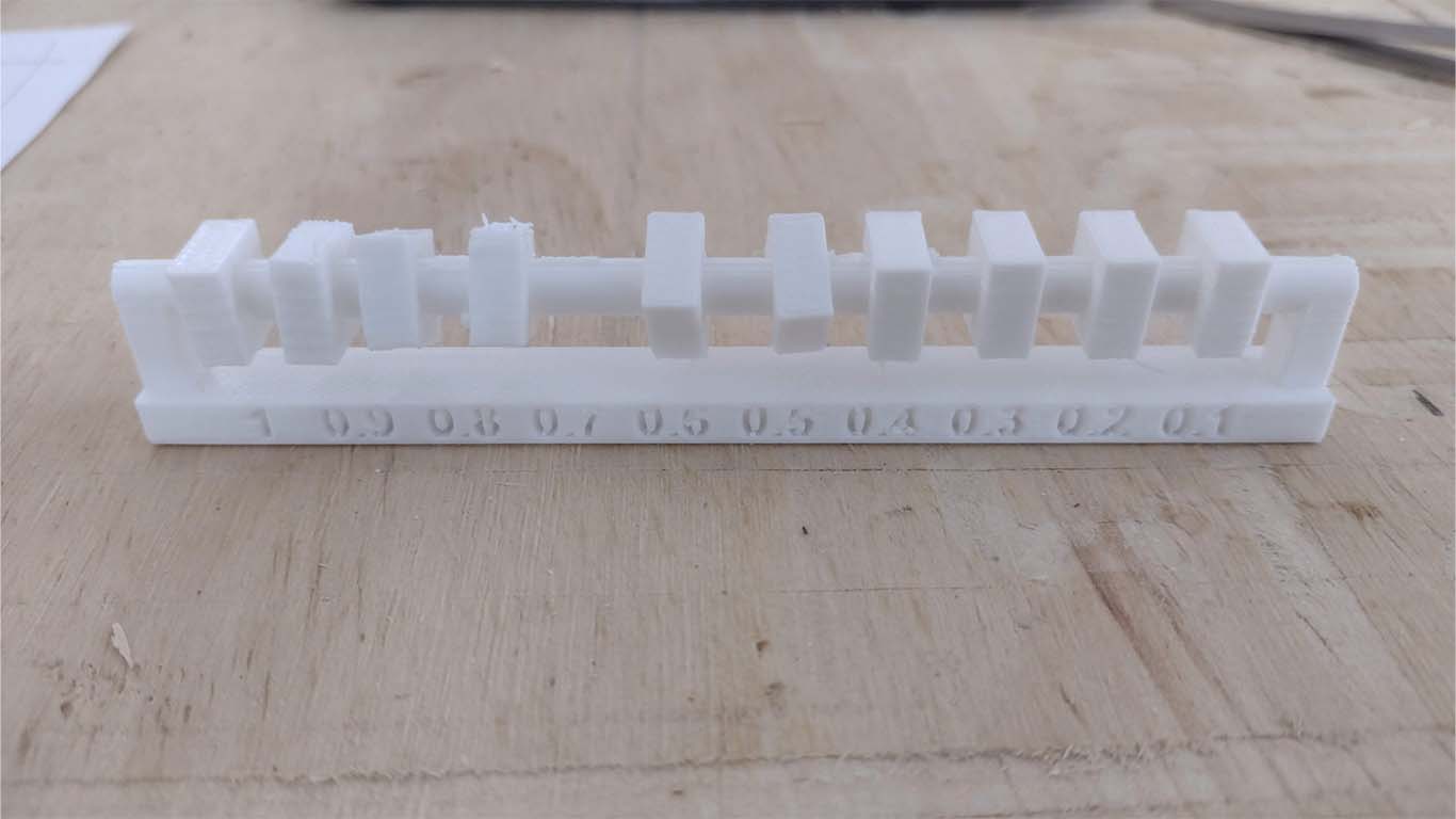
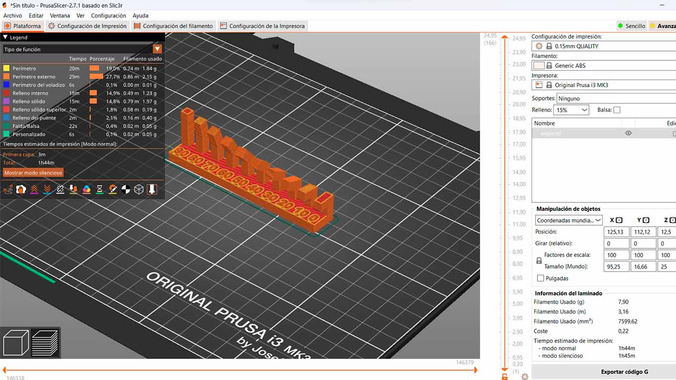
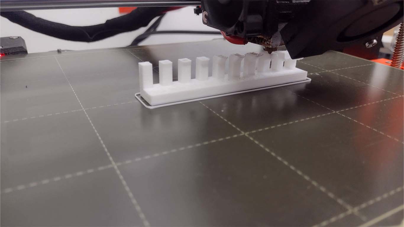
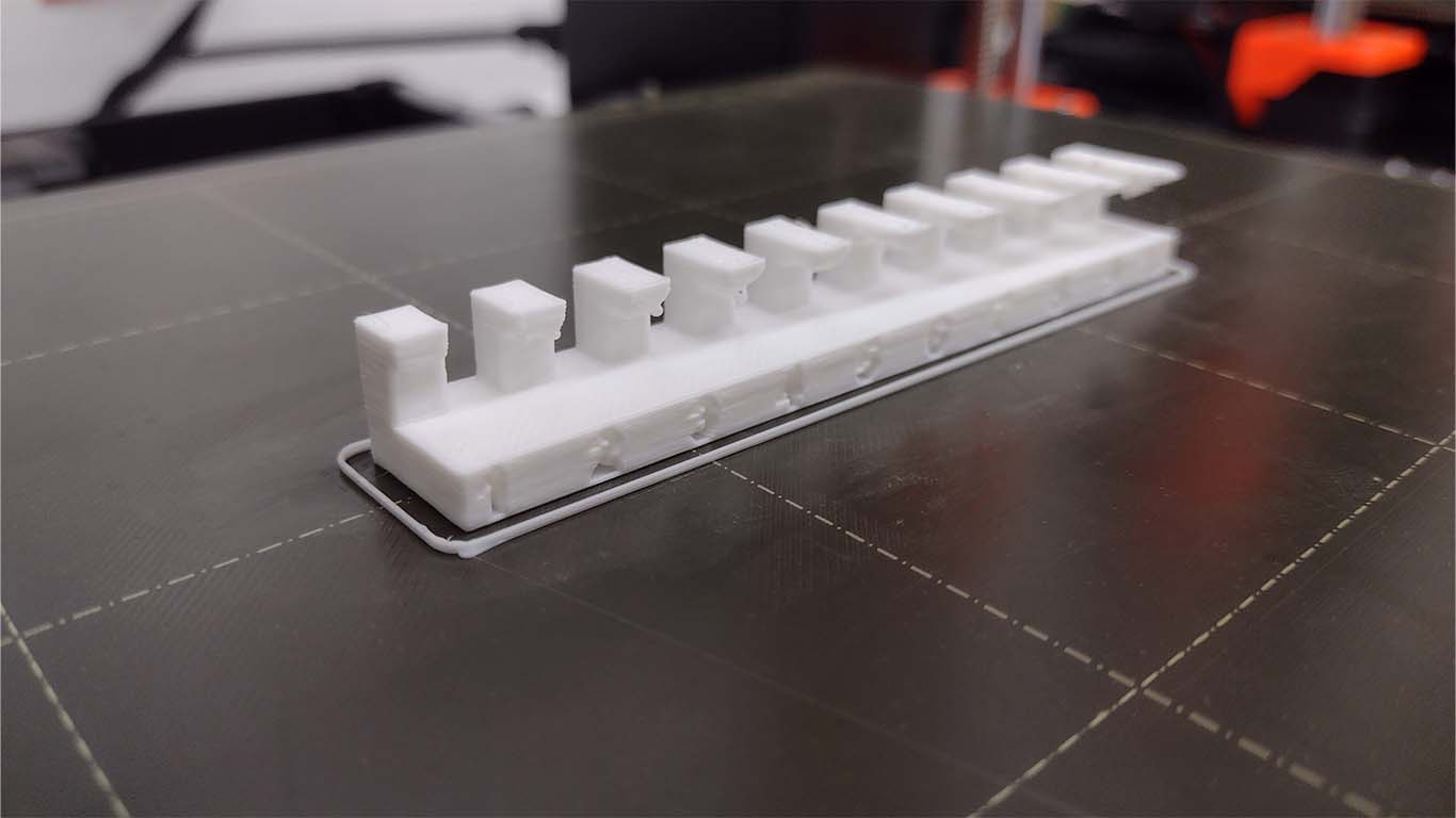
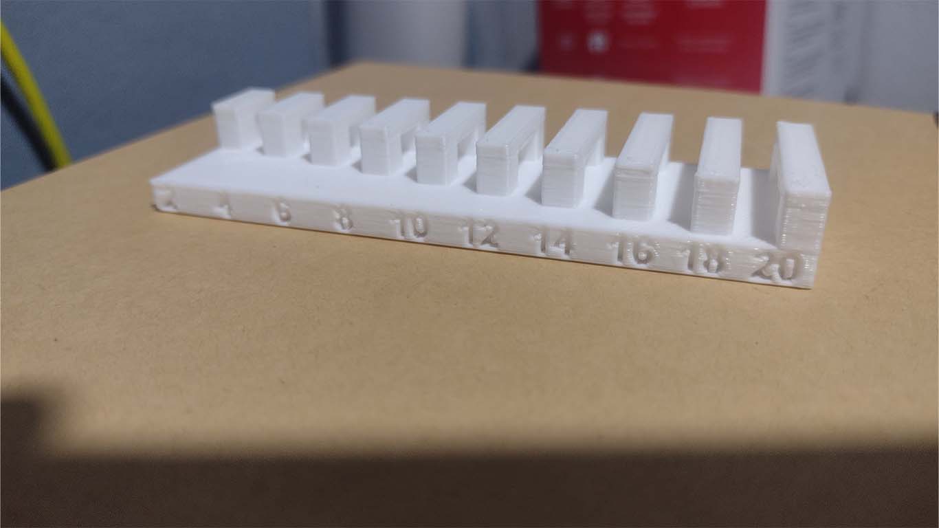
TEST ANGLE
The first test without supports is the angles, where the modeling presents volumes that change their angle. The 3D printer was able to achieve a good result according to the reference presented in class.
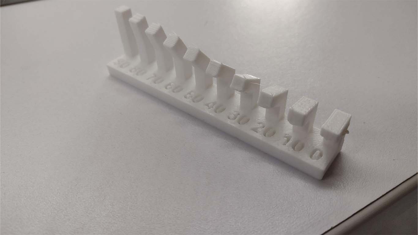
CONCLUSIONS: For the next test, the 3D printer was able to carry out the modeling normally, however in the numbers, 0, 10 and 20 it had a slight difficulty and the modeling is not so clean because the complete figure is not shown. The double part in the numbers mentioned looks like lumps of filament that are there and the machine was able to achieve the shape but not as well formed.
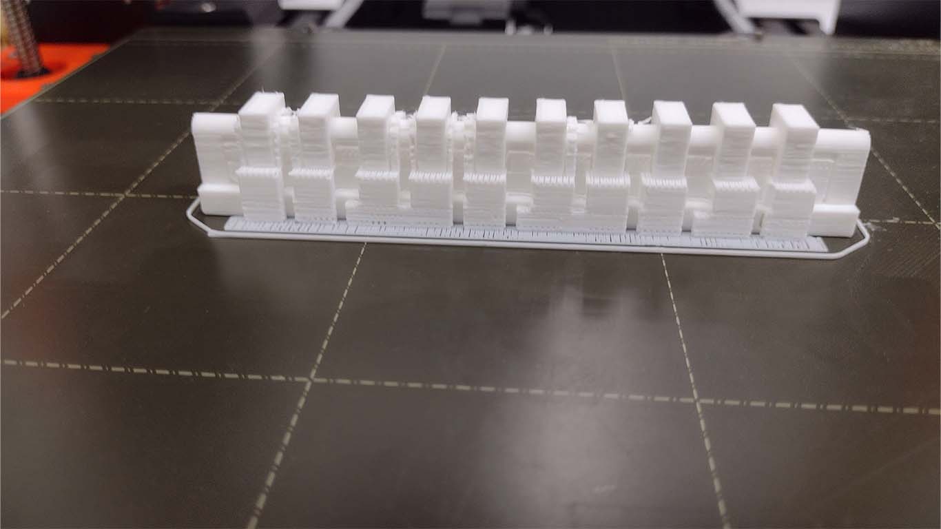
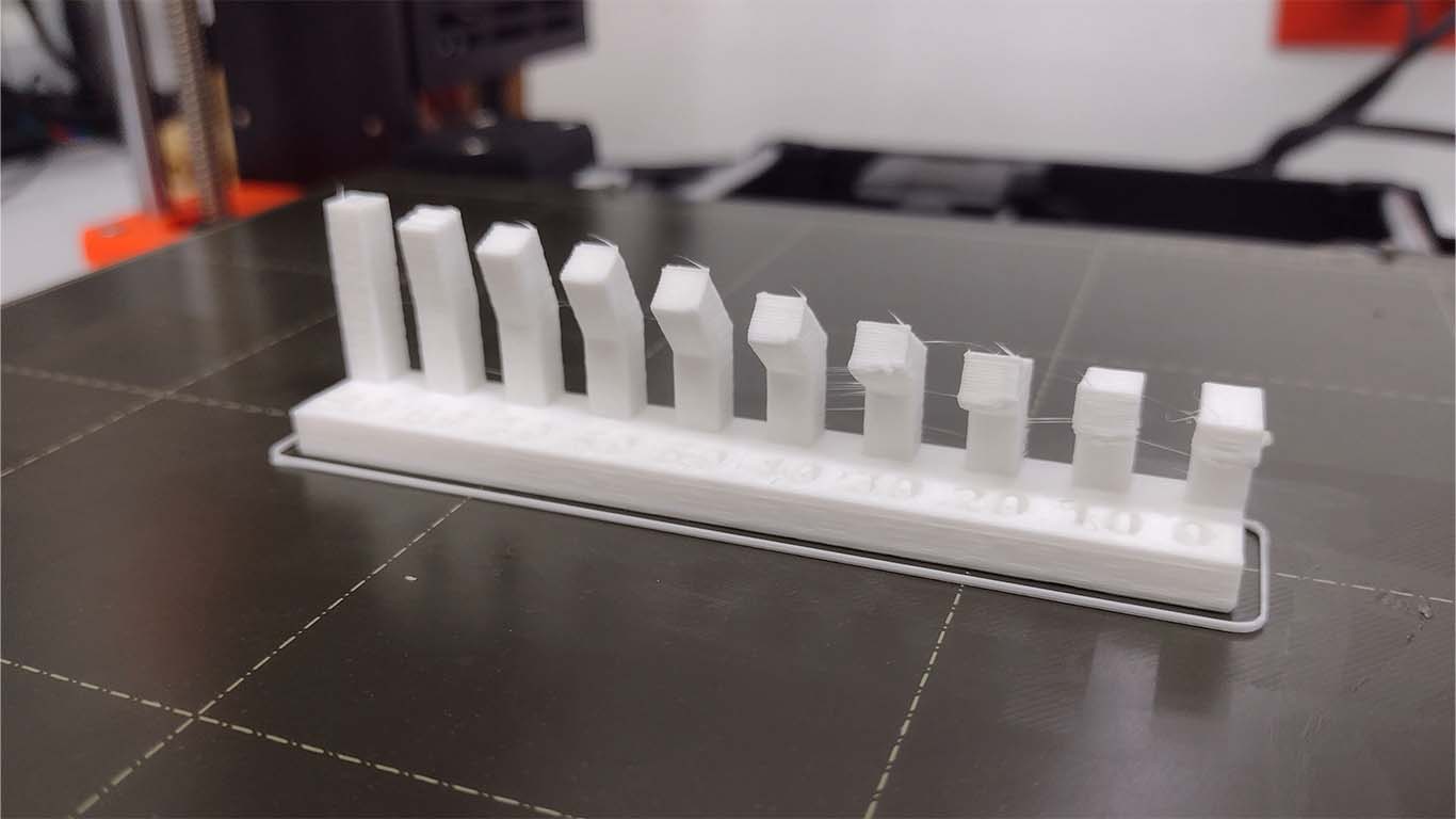
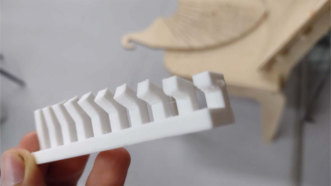
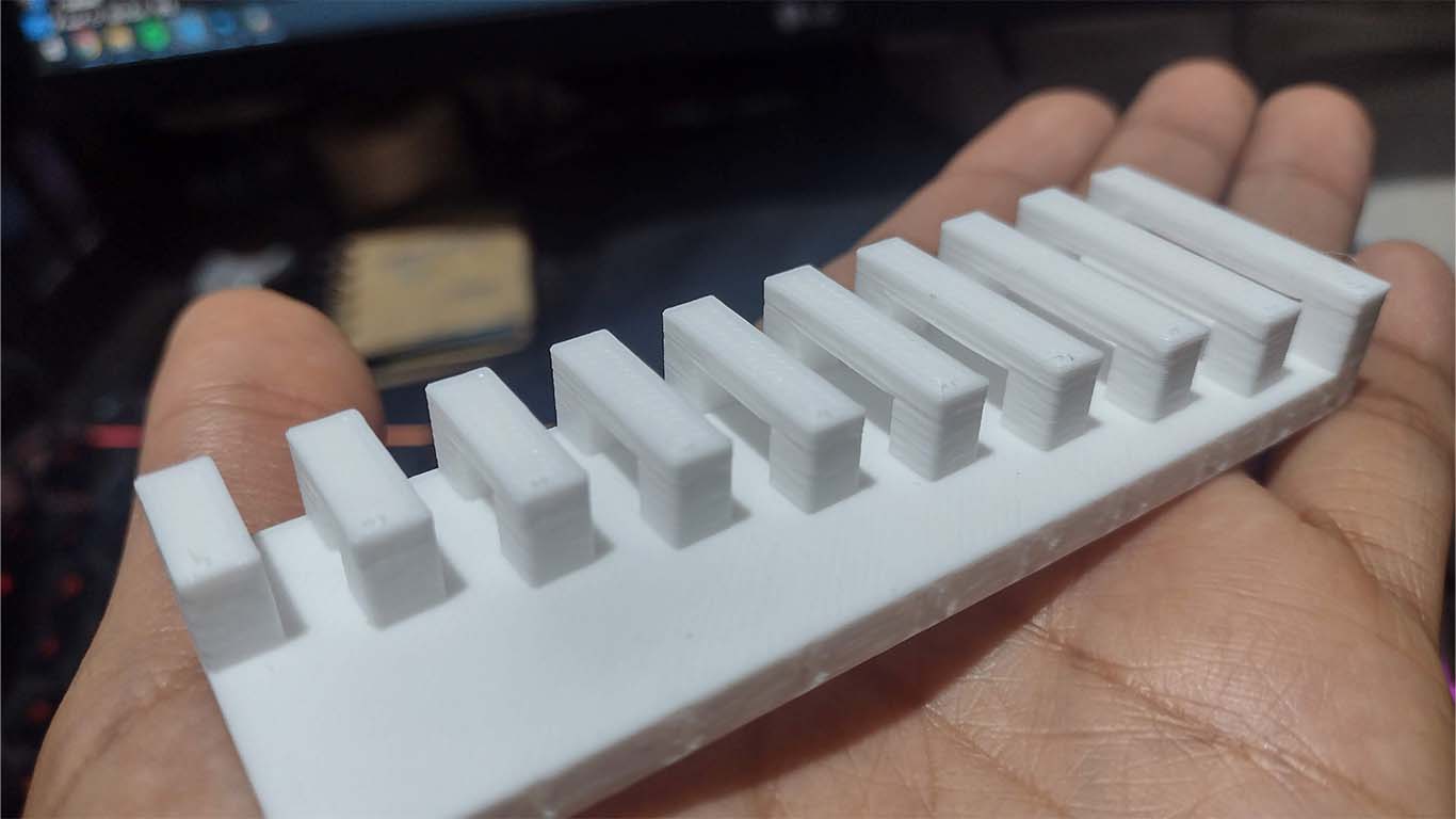
TEST OVERHANG
La segunda prueba es muy similar a la anterior pero el modelado presenta un ángulo recto donde la distancia de vuelo de cada prisma aumenta.
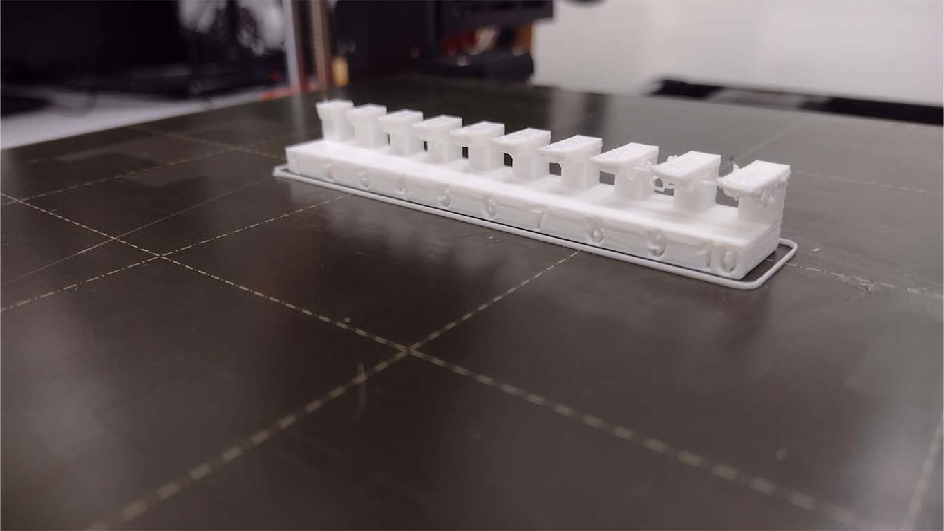
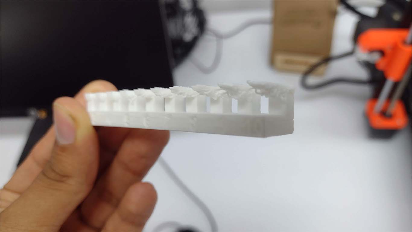
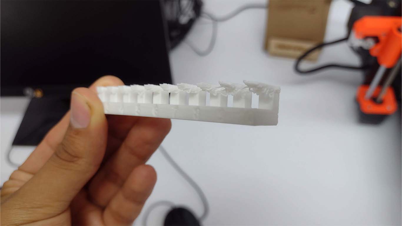
CONCLUSIONS: For the next test, the 3D printer was able to model the overhangs, but as can be seen in the photographs, it had problems starting with number 7, where at the bottom of each overhang there is something very similar to the previous test, small clumps of filament that are overlapping because the machine could not achieve the clean shape and due to the size of the ruffle. We can conclude that the machine needs supports from number 7 to achieve a better finish.
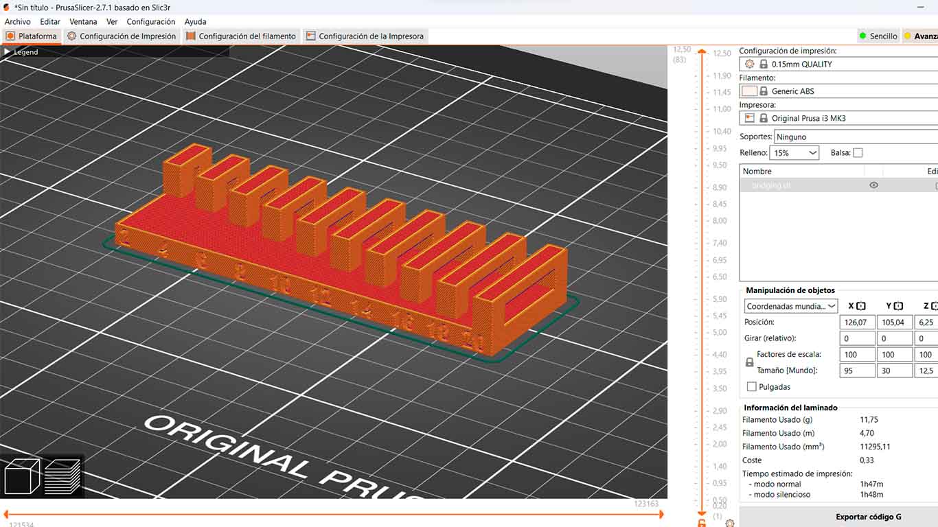
TEST BRIDGING
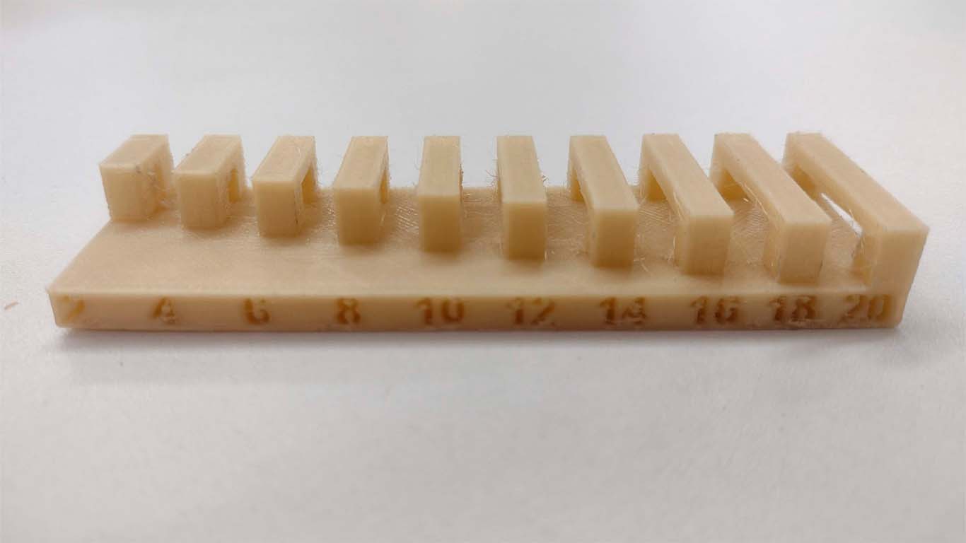
The next test has the concept of porticos where the modeling varies the distance between the supports and in the end achieve a bridge to see if it is possible. The result came out well with a lot of filament around it but after cleaning it a little you can get the result.
In a first test, a test had been done before doing the retraction test and it came out like the following photos. From there the respective changes were made to the configuration and we can see that the model was achieved.
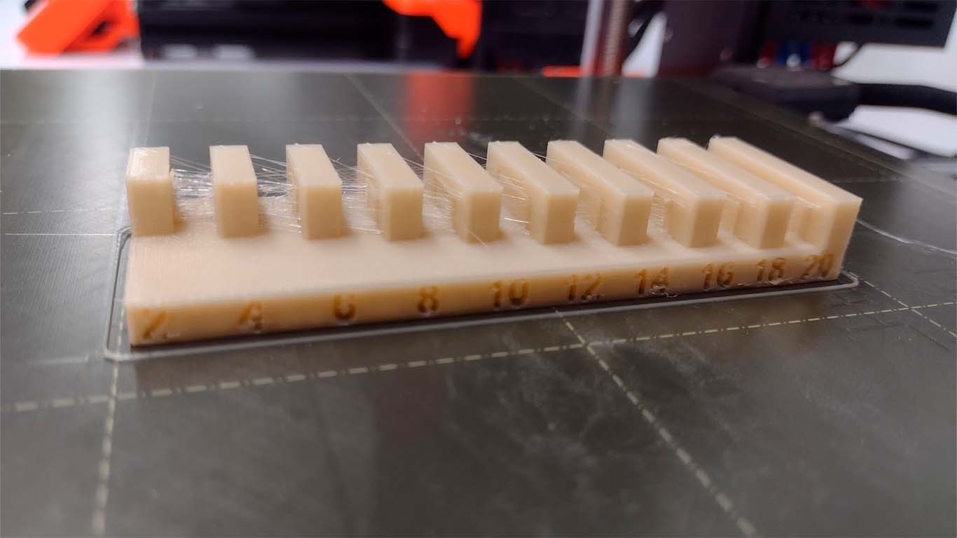
The following photographs are the model with the configuration changed due to the change in the retraction and extruder temperature values.
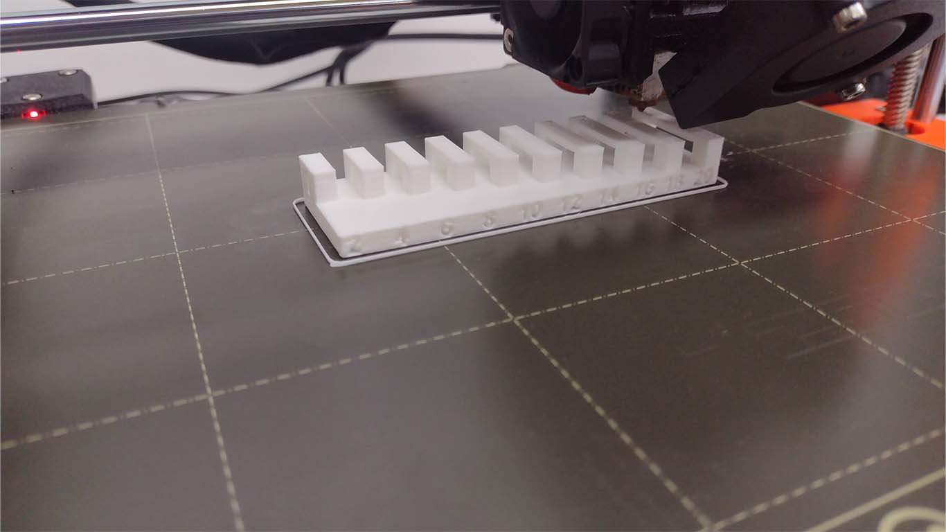
CONCLUSIONS: I am surprised by the difference between the 2 tests performed after understanding the retraction test. The printer in the 2nd test was able to achieve the shape cleanly and without supports. It doesn't have as many cobwebs as the first test and I was very amazed by the way the machines can be improved with simple configurations.
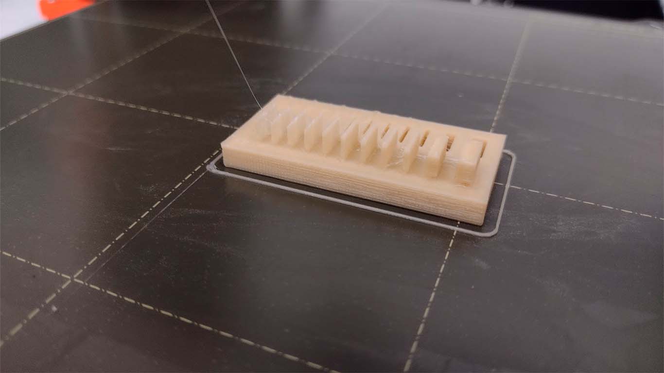
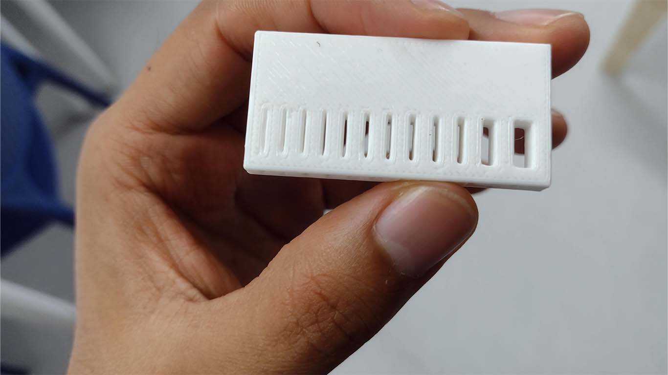
TEST WALL THICKNESS
The next test shows small rectangular holes as small walls on the other side. The printer was able to make the print as found in the modeling, only there is a lot of excess filament and it did not come out as clean as the reference.
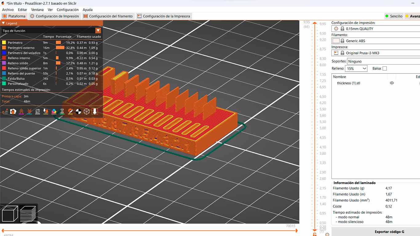
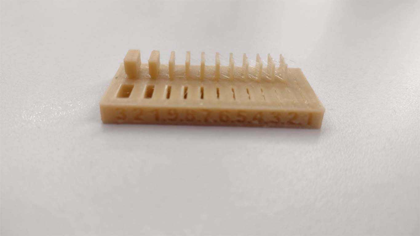
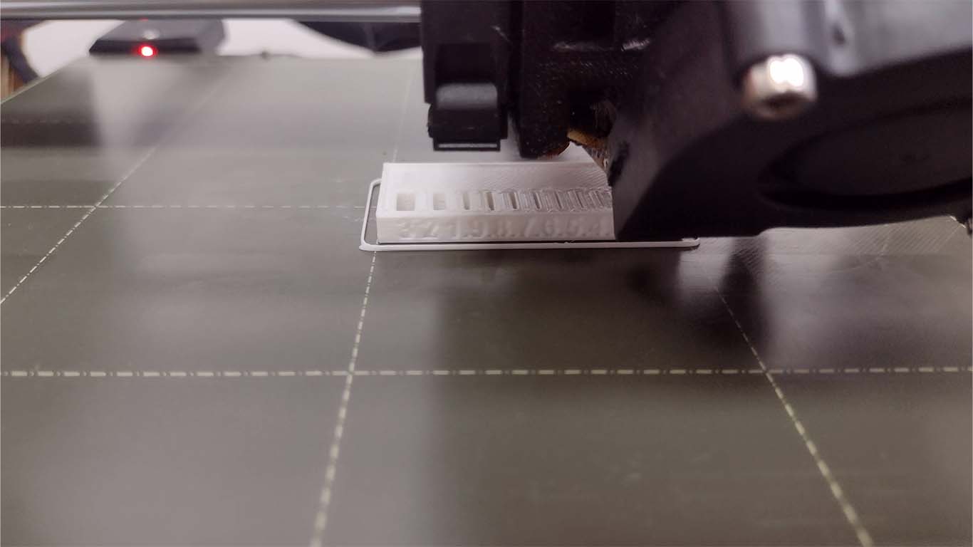
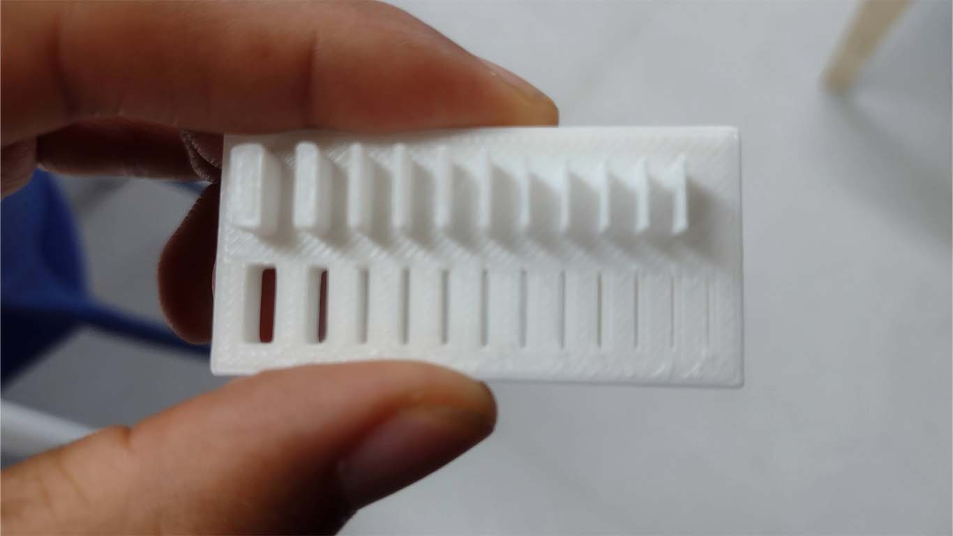
After doing the first test, we wanted to print the 3D model again because it came out with a lot of cobwebs and it was not a suitable print. Therefore, in the next test the extruder temperature settings and also the retraction value are changed to obtain a better print and here are the results.
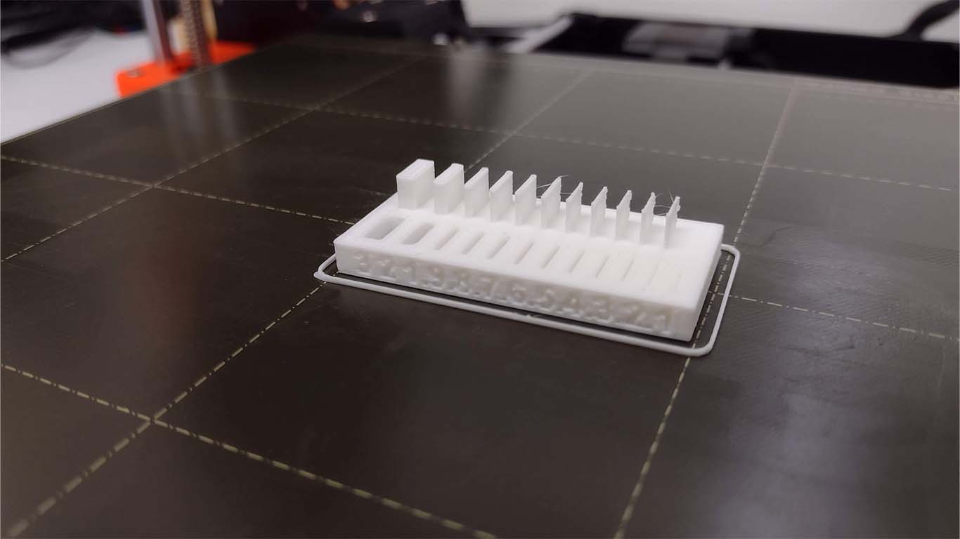
After obtaining the 3D print, we can see that the print came out cleaner than the previous test, but it was not possible to print wall number 1 that has the model due to the thinness of the model. On the other hand, the holes came out well, only in number 1 it is not very clear since it can be seen that the hole is very glued.
CONCLUSIONS: We can see that the finish in both tests is very different and like the previous tests and this is because the configuration that both have are different and we can see that it is important when printing the models. In both we did not obtain good results with the wall number 1 but with the rest it went well.
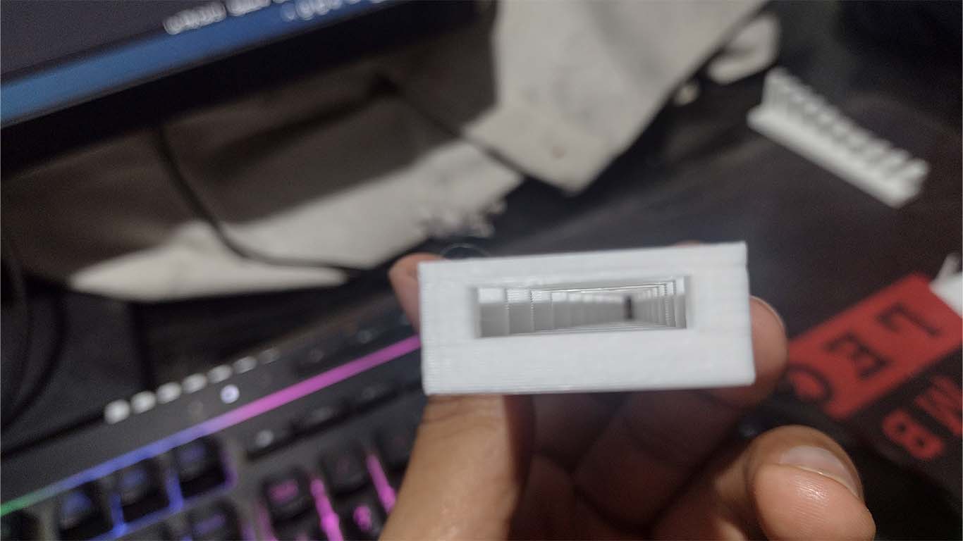
TEST DIMENSIONS
In the test we were able to print the model clean and according to the reference, however the numbers found were not so clear.
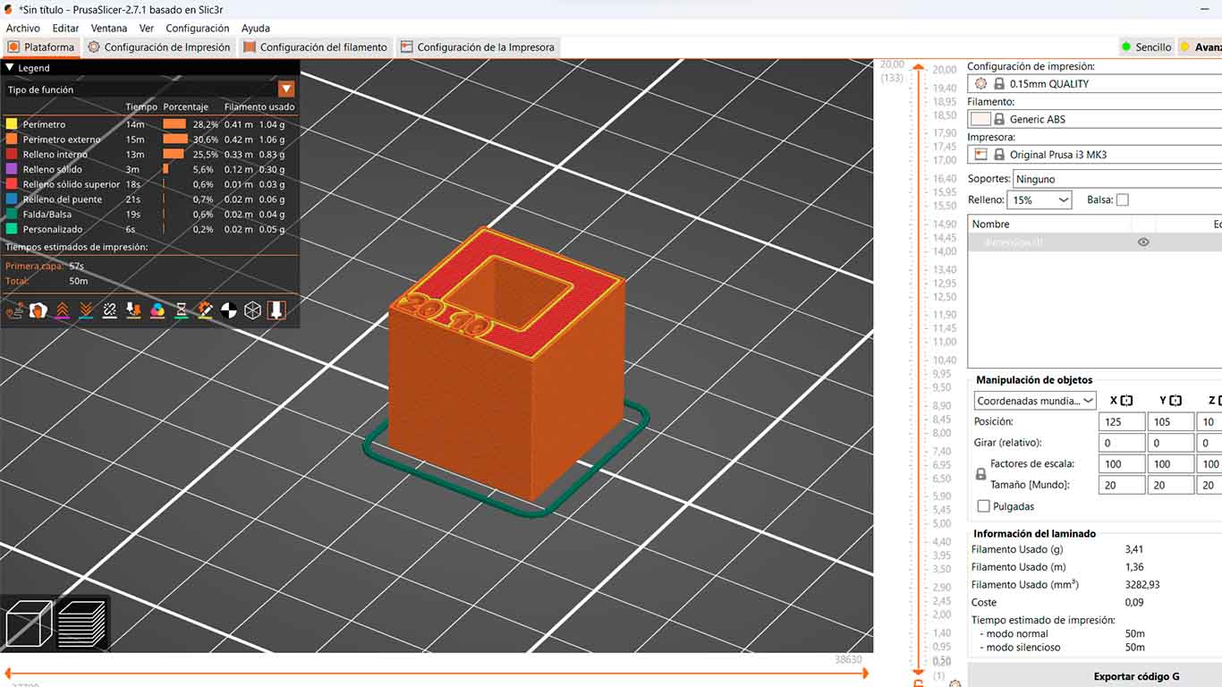
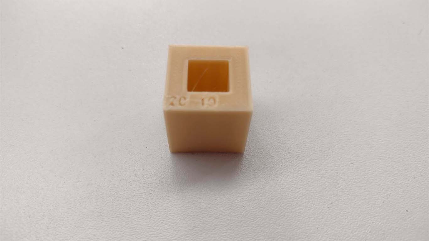
CONCLUSIONS: In the following test, since it is a compact vertical element and does not present so many difficulties, the printer was able to carry out the modeling correctly, only at the level of detail if it was not successful according to the model since the numbers that present the model are not so clear. . But with the shape and interior of the model everything is fine.
TEST ANISOTROPY
This test is the smallest, fastest and the printing result came out very well compared to the class reference.
CONCLUSIONS: The next test the 3D machine was able to achieve it in shape and finish.
TEST SURFACE FINISH
The next test was about seeing the finish and changing the figure from orthognal to sphere that the 3D printer was able to make and obtain a good result.
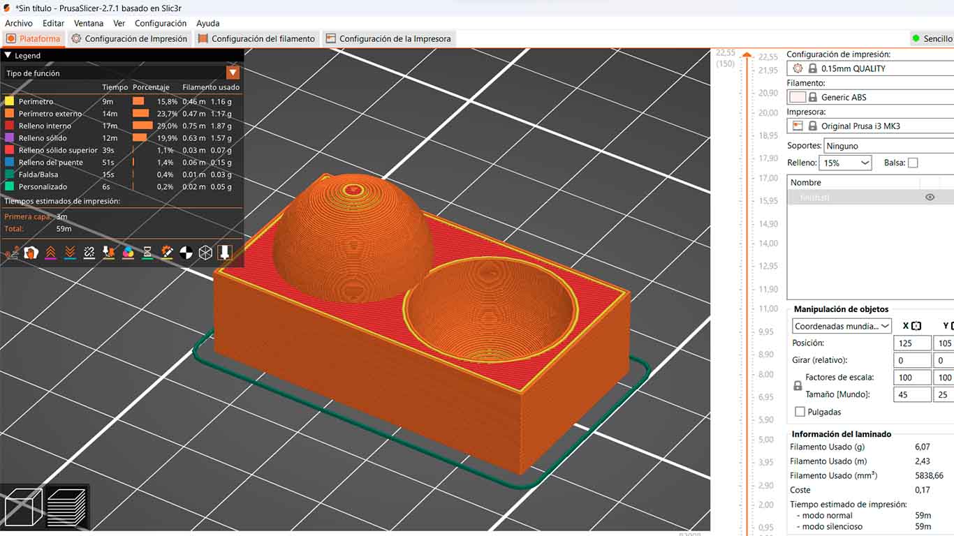
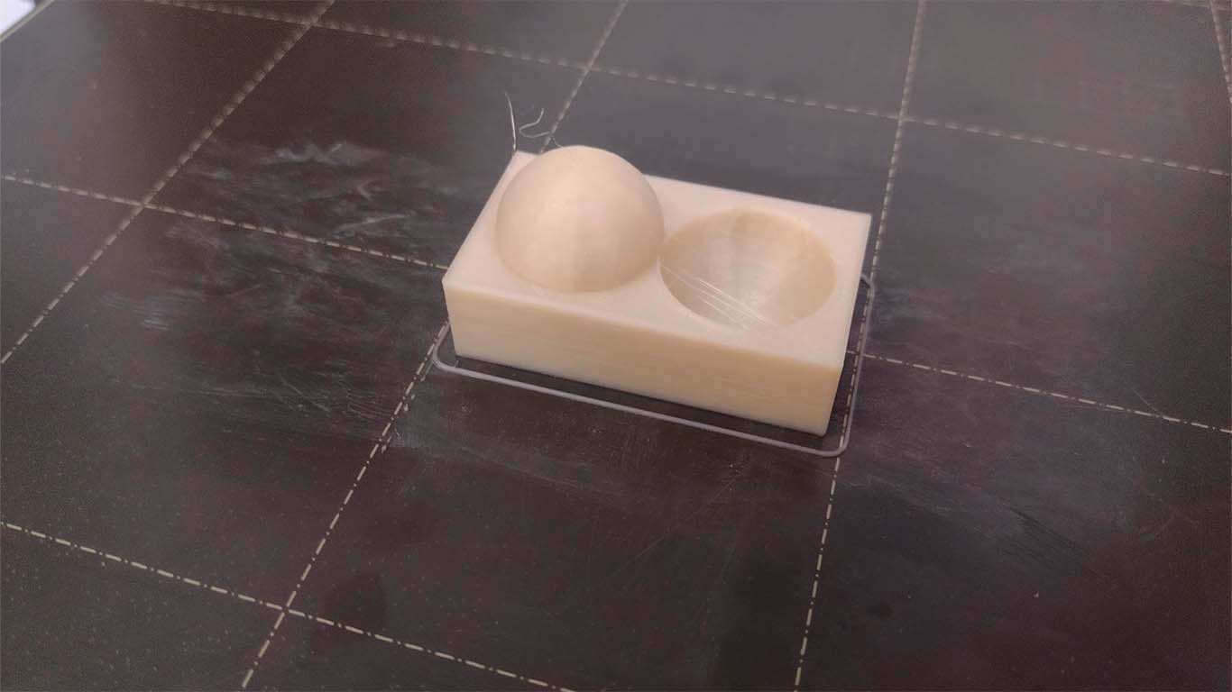
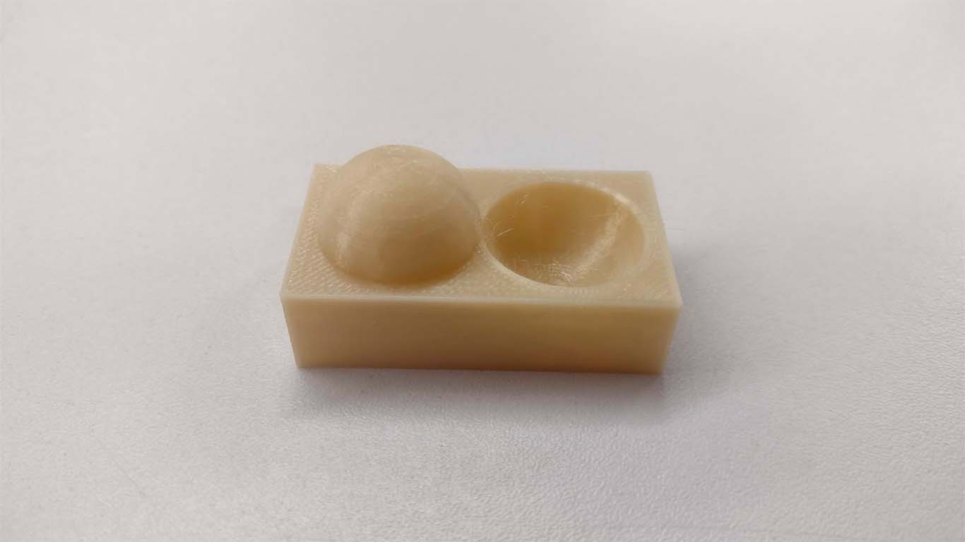
CONCLUSIONS: In the following test I can conclude that the machine was able to achieve the objective of the test in seeing that a good finish of the models can be achieved. Here by presenting a curve, the machine was able to achieve both the low level and high level, impressive detail and it was really achieved.
TEST INFILL
And the last test, the 3D printer was able to perform and have good detail in the finishing of the test. The number 15 is seen very clear and clean throughout the depth of the cube.
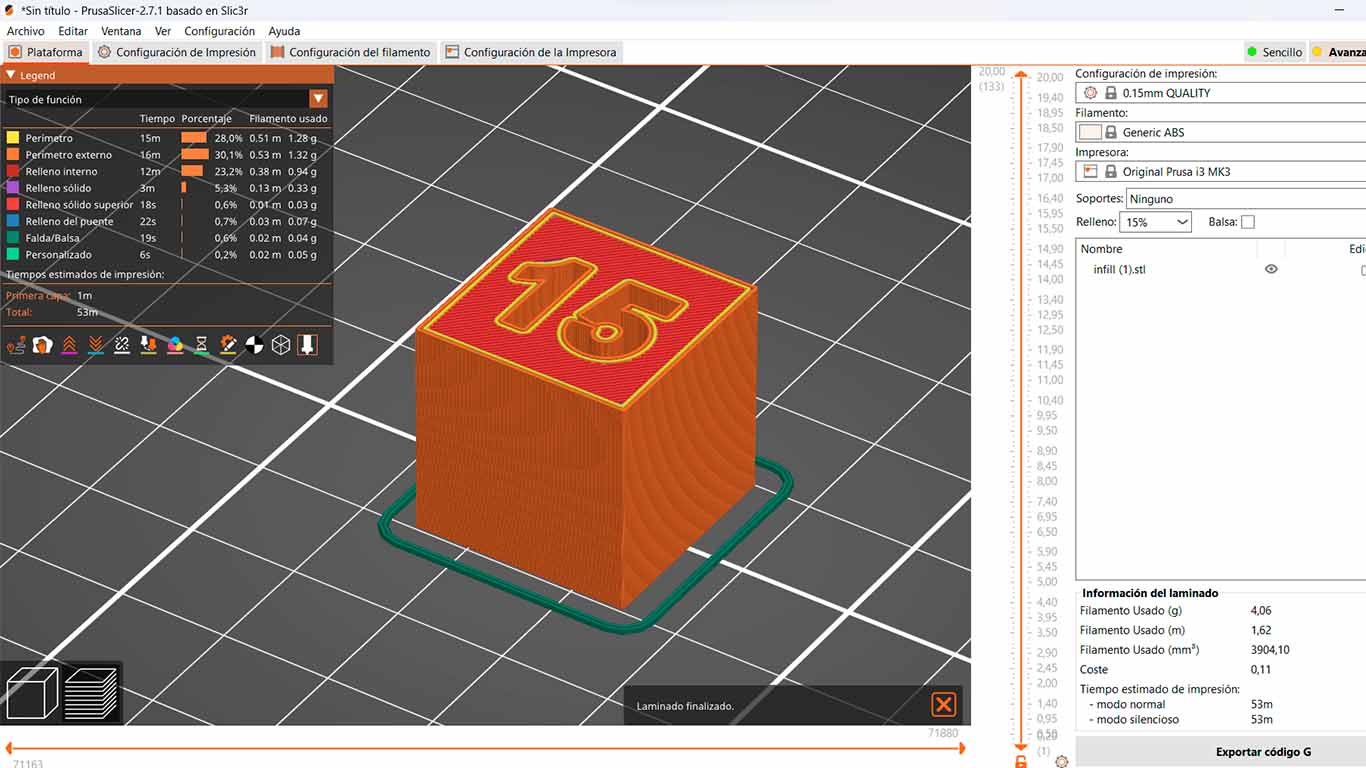
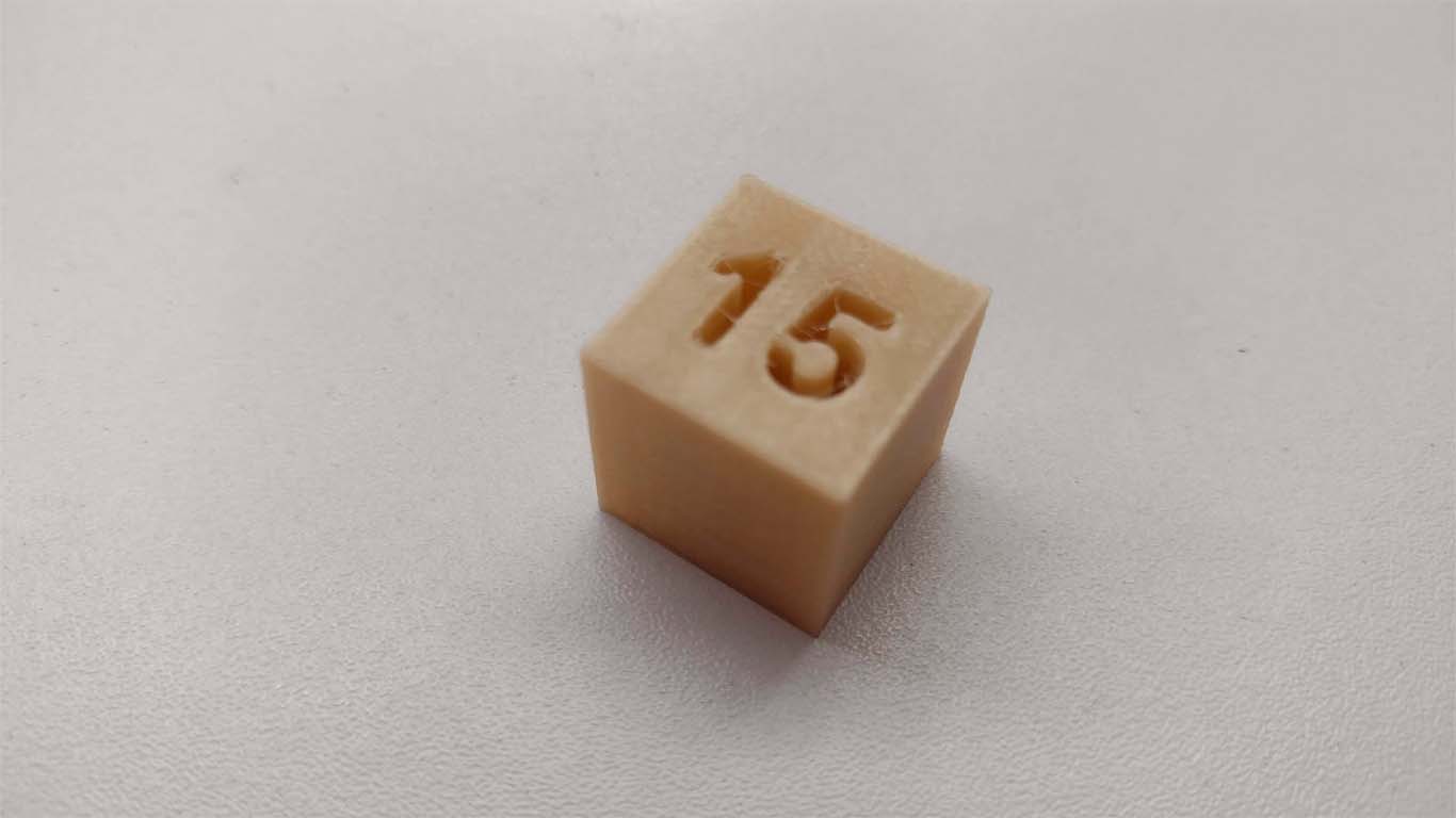
CONCLUSIONS: Finally, in the last test, you can see that the model came out in accordance with what was awarded by the FAB ACADEMY. It is only seen that within the number there are few cobwebs that could be improved by changing the retraction configuration.
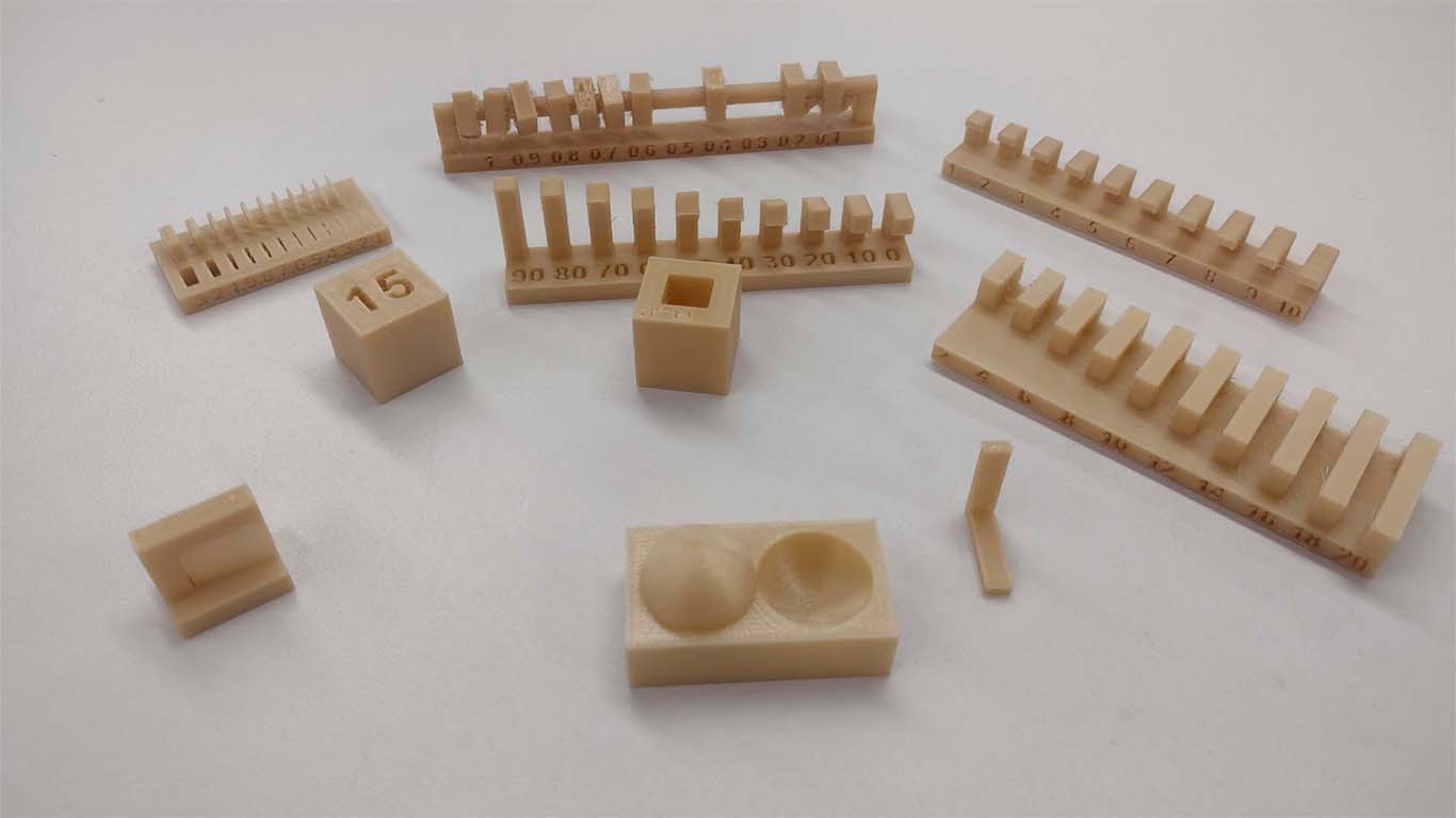
Here we can see a photo of all the tests carried out with the PRUSA MK3, which obtained good results, some configurations needed to be adjusted but the objective was achieved.
INDIVIDUAL ASSIGNMENT
DESIGN AND PRINT 3D OBJECT SUBTRACTIVELY
MODEL AND DESIGN WITH BLENDER
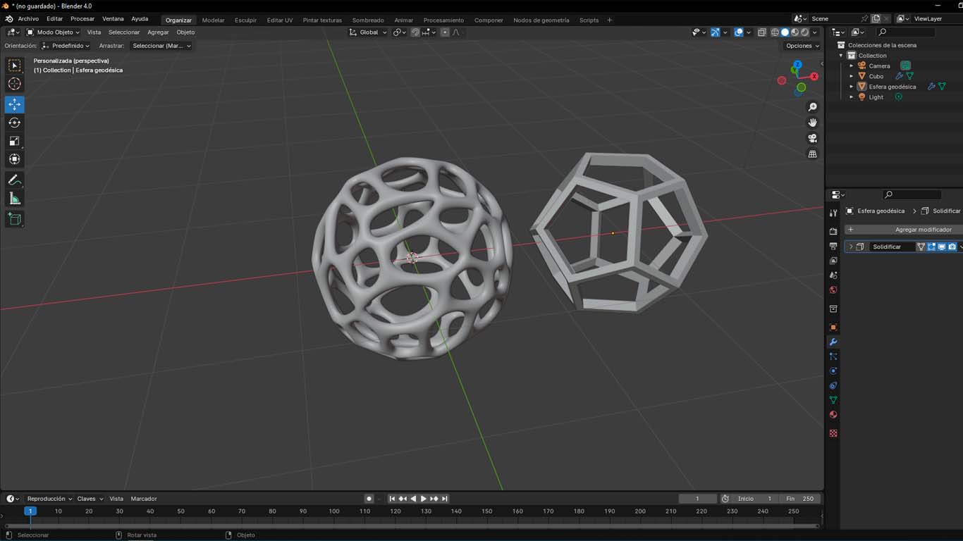
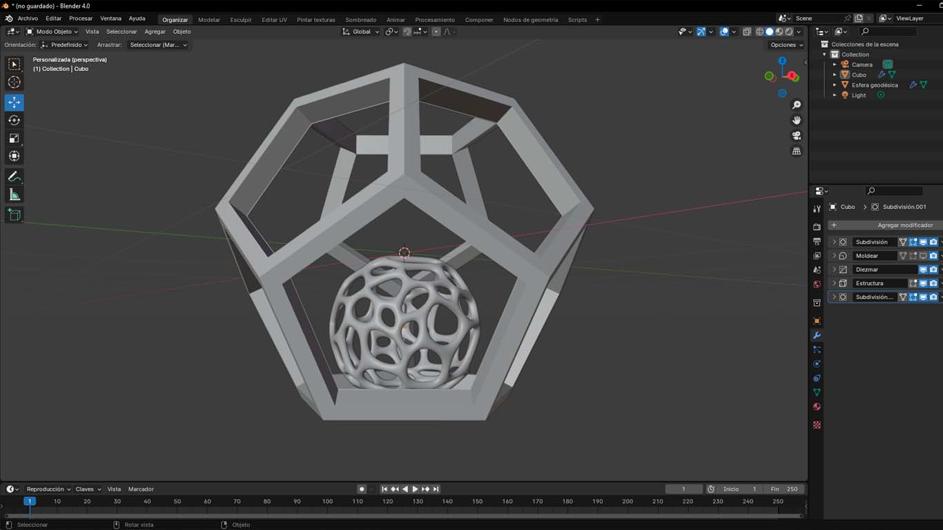
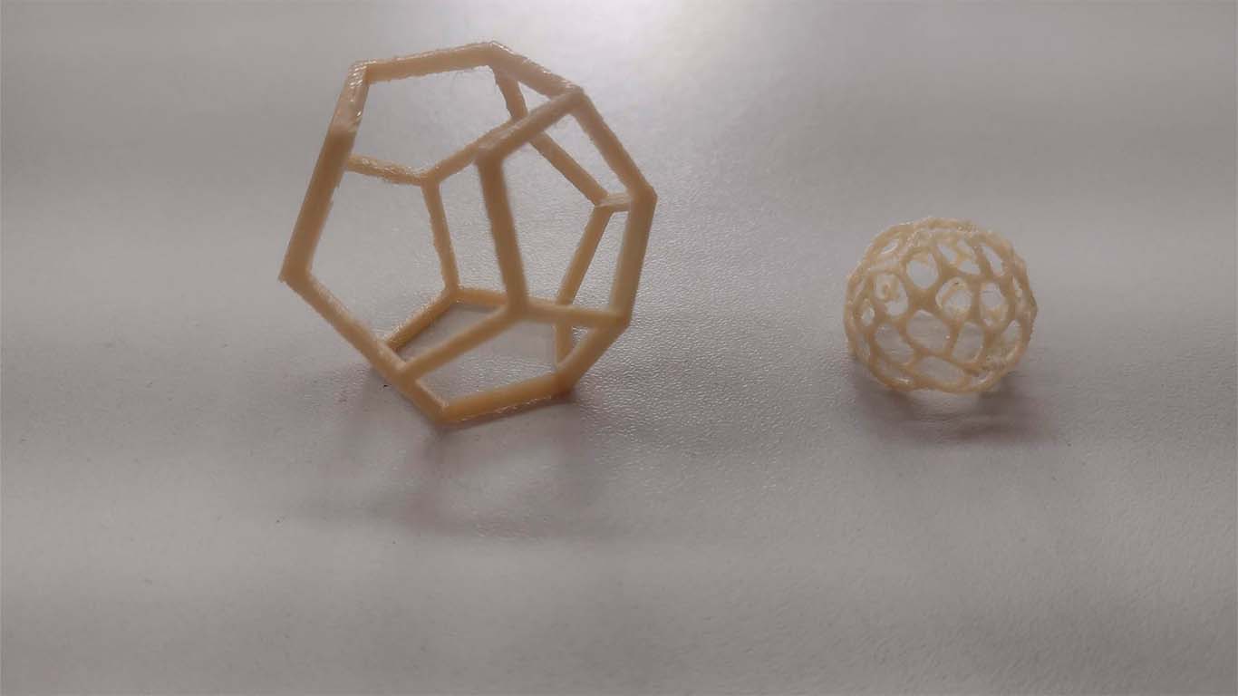
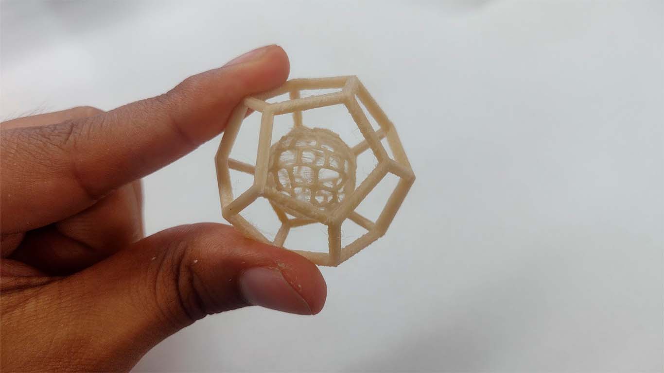
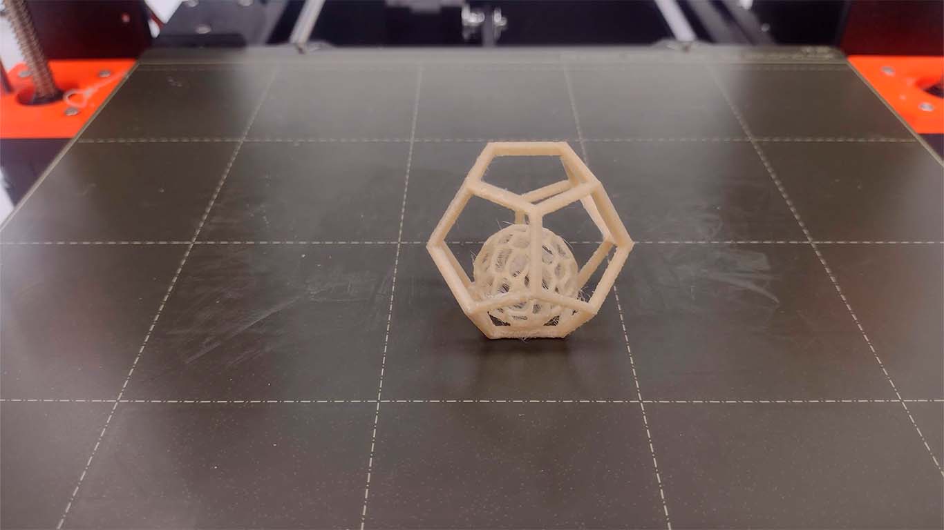
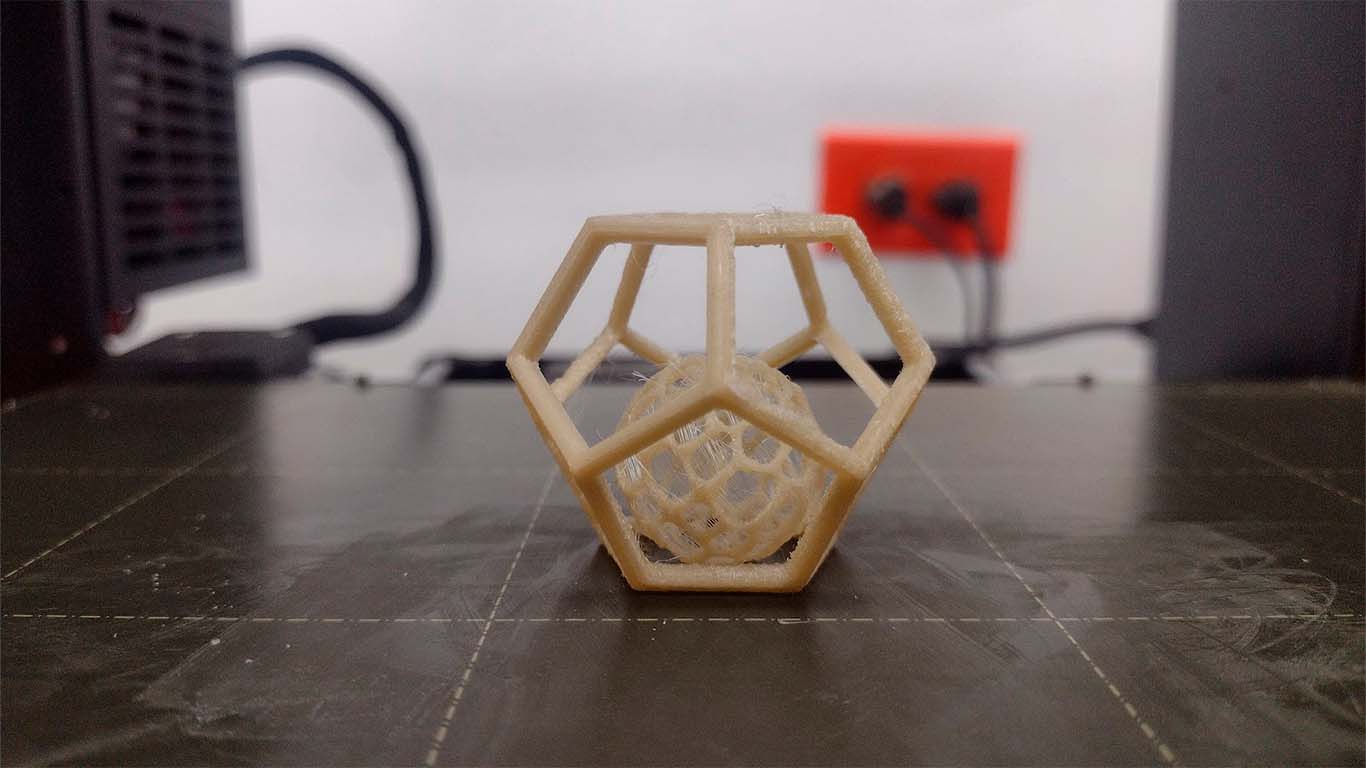
For my individual assignment I wanted to make a complicated geometry to put the 3D printer in trouble. The idea was to generate a DODECAHEDRON , which is a 12-sided polyhedron that is empty and only has the edges made and that inside has a VORONOI -type sphere that can move and meet the objective of the assignment.
First we will open the BLENDER program, where we will first develop the dodecahedron. Below I will show the steps I took in the program to achieve the figure I was looking for.
MODELING A DODECAHEDRON
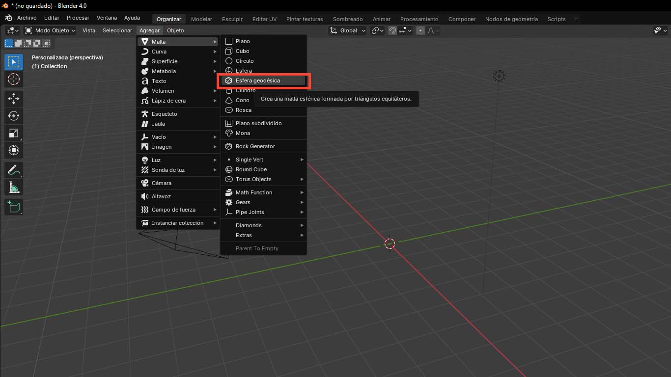
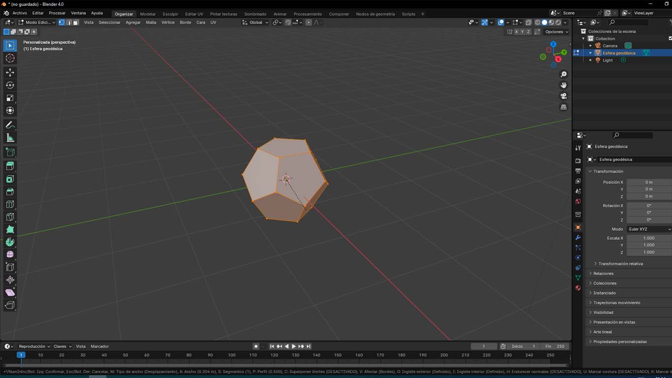
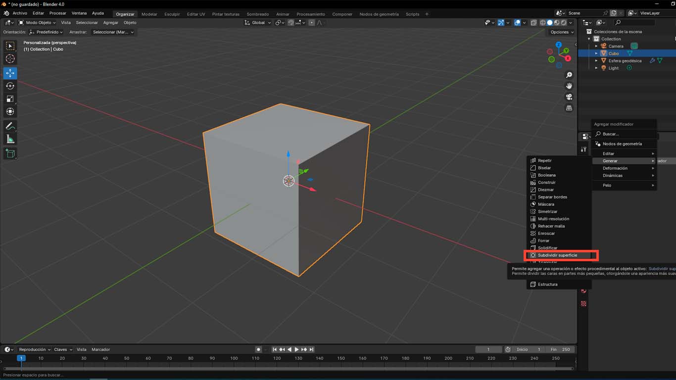
We will start by adding a GEODESIC SPHERE that the program gives us and we will obtain a default modeling of the program, here we will begin to configure the sides and faces of the dodecahedron figure.
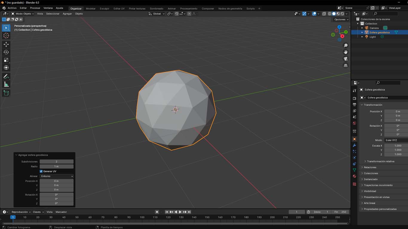
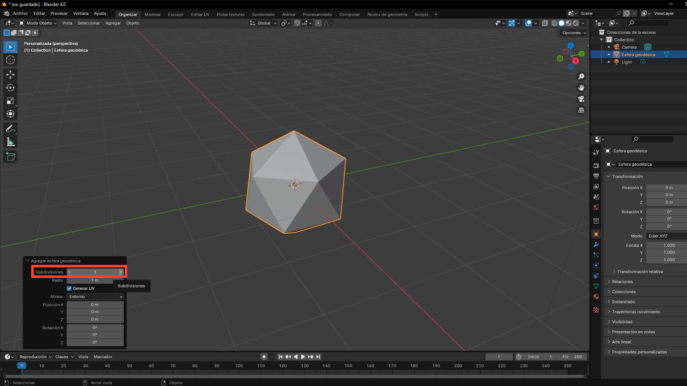
Then in the settings box that appears, we have to change the SUBDIVISIONS option that has a value of 2 to a value of 1 and with the TAB button on the keyboard we go from "OBJECT MODE" to "EDITING MODE" .
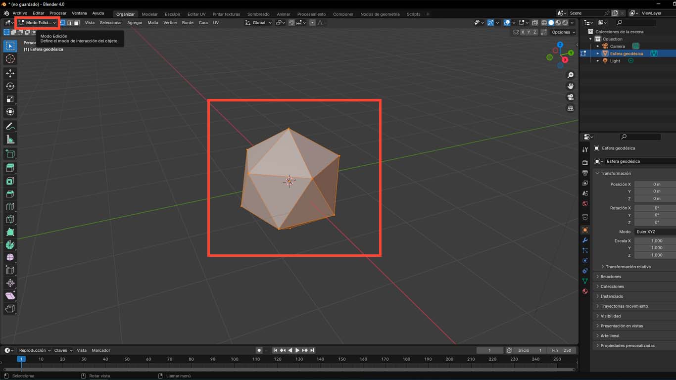
Then when the EDIT MODE is activated and the modeling is orange, we press CTRL + B where we can edit the number of faces and we have to achieve the shape we want to achieve, in my case it will be a figure with 10 sides.
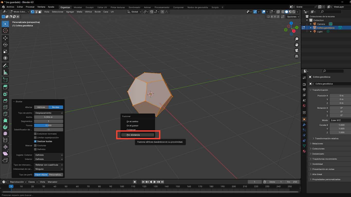
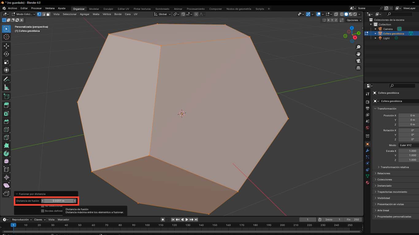
After obtaining the shape we want, press the M button on the keyboard and choose the BY DISTANCE option and modify the distance of the vertices to achieve a clean figure.
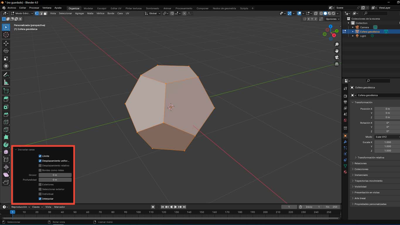
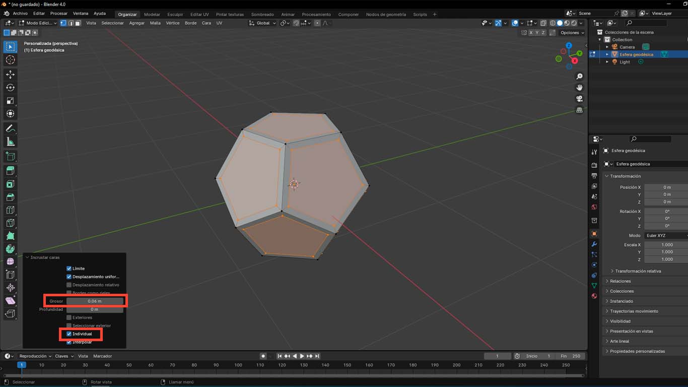
Then you press the I button on the keyboard, where we activate the INDIVIDUAL option and we will modify the THICKNESS option to give volume to the edges of the modeling.
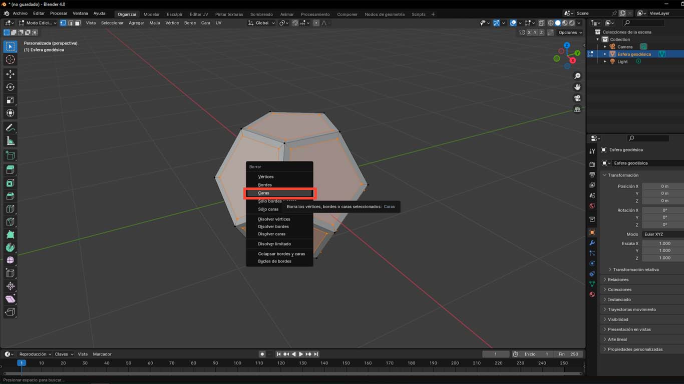
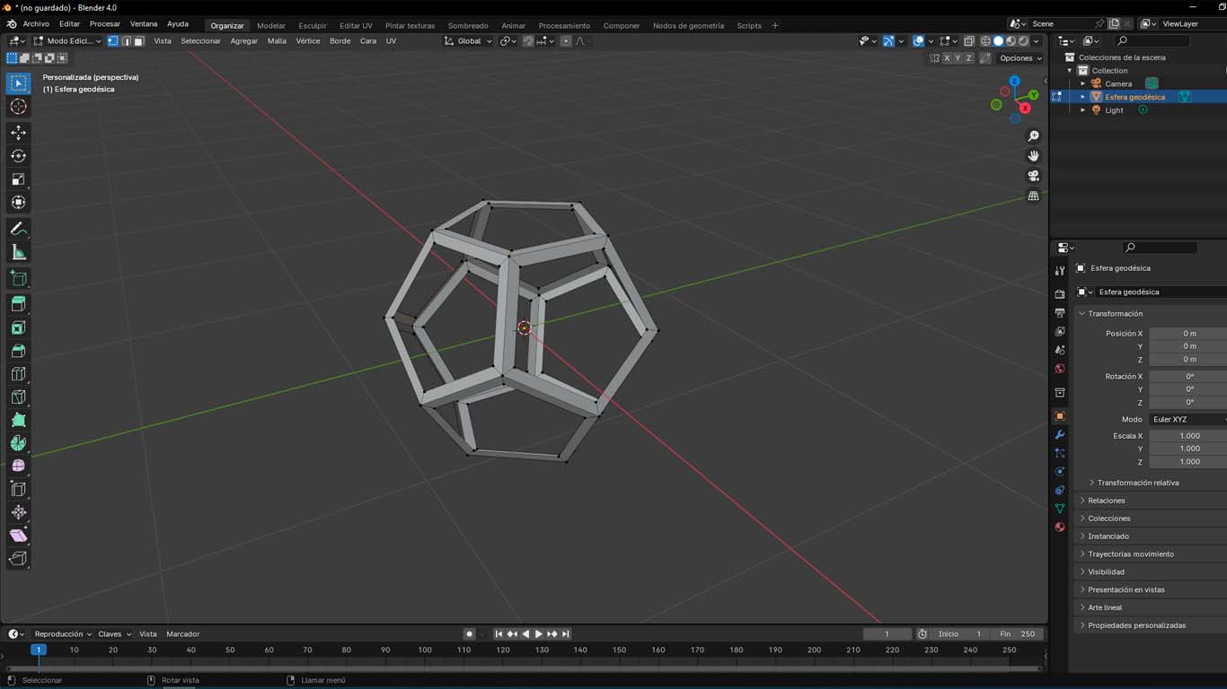
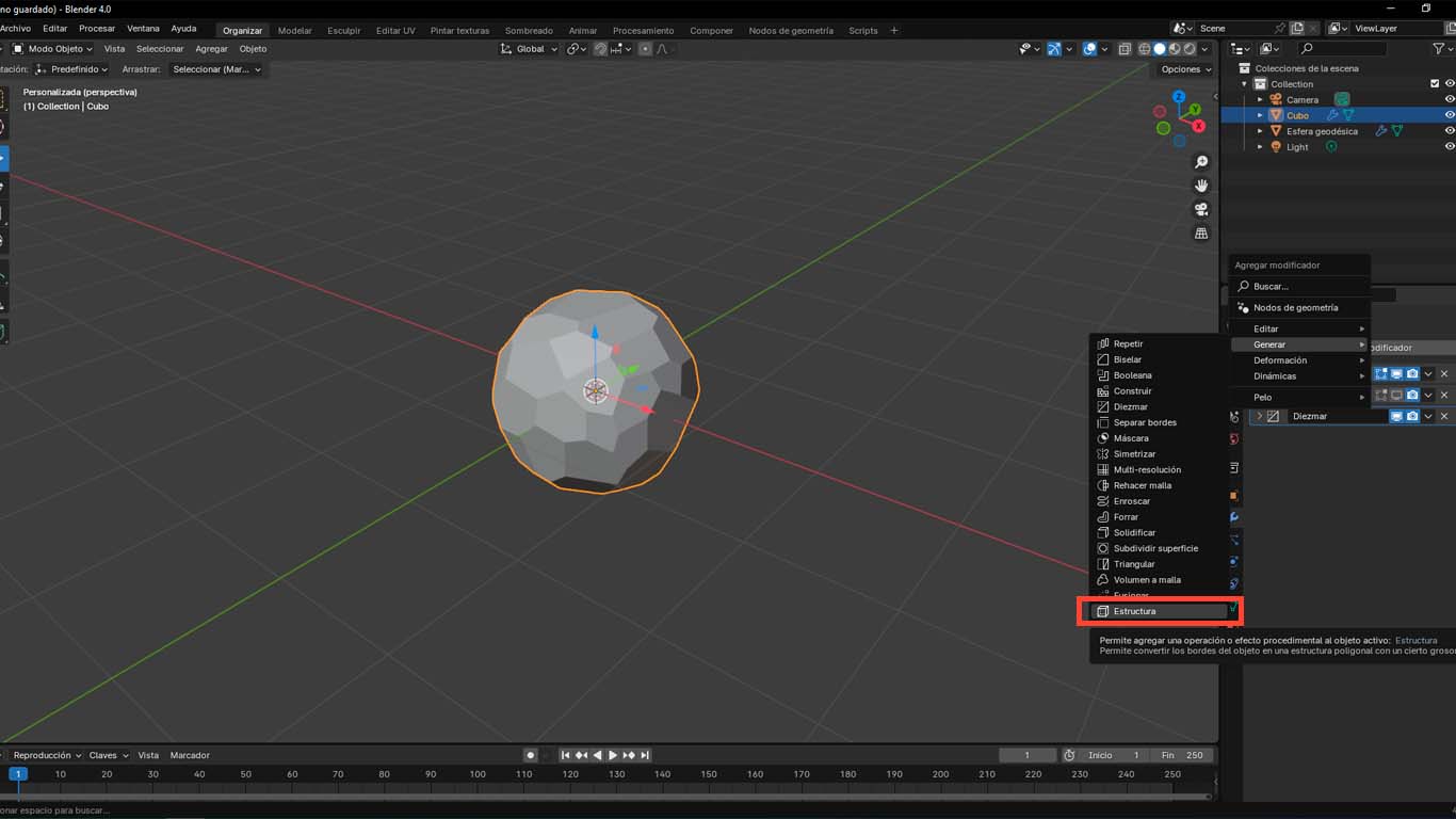
We press the X button on the keyboard and then select the FACES option, which will eliminate the faces from the modeling and we will only obtain the edges of the figure.
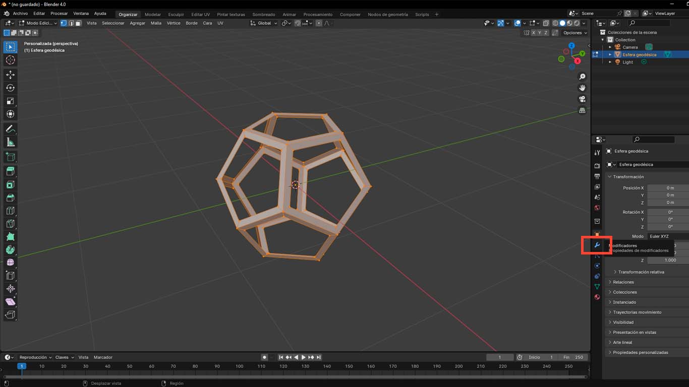
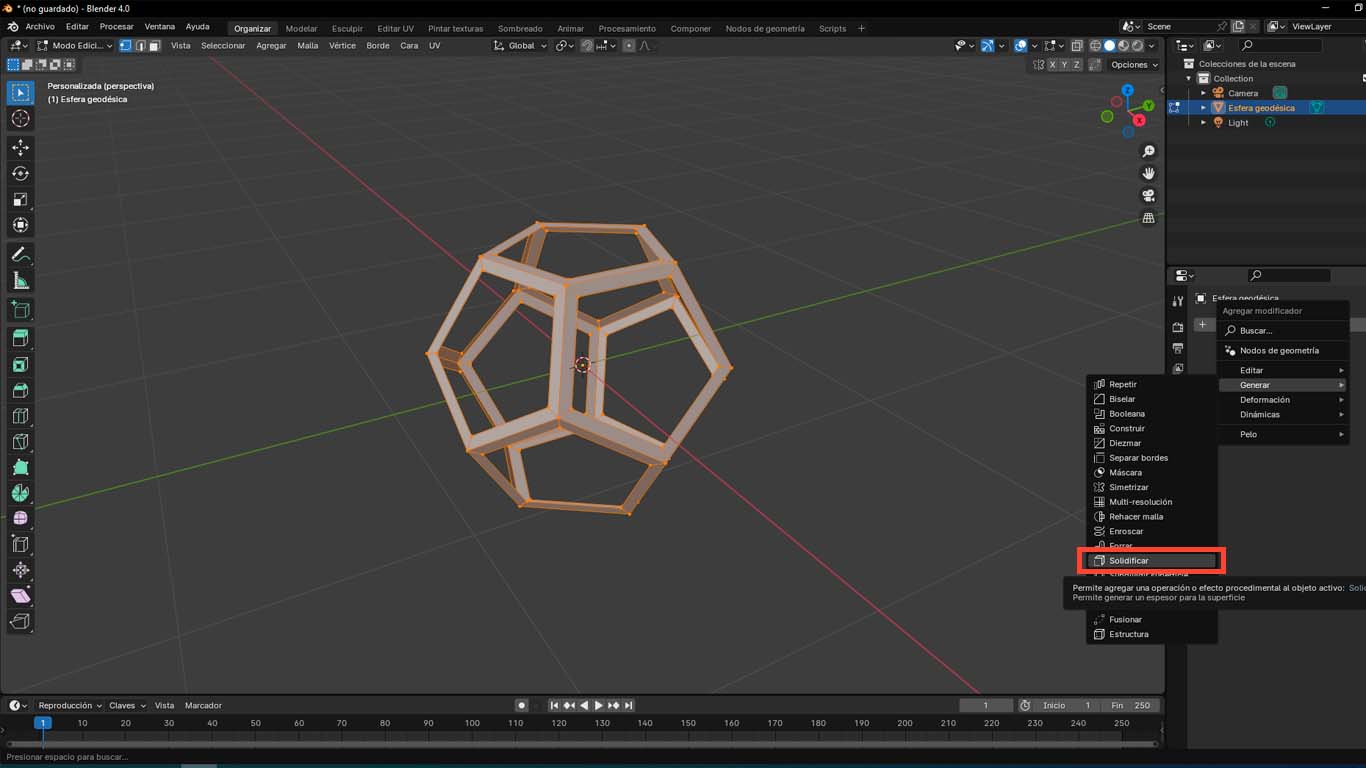
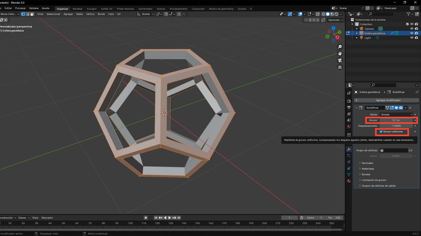
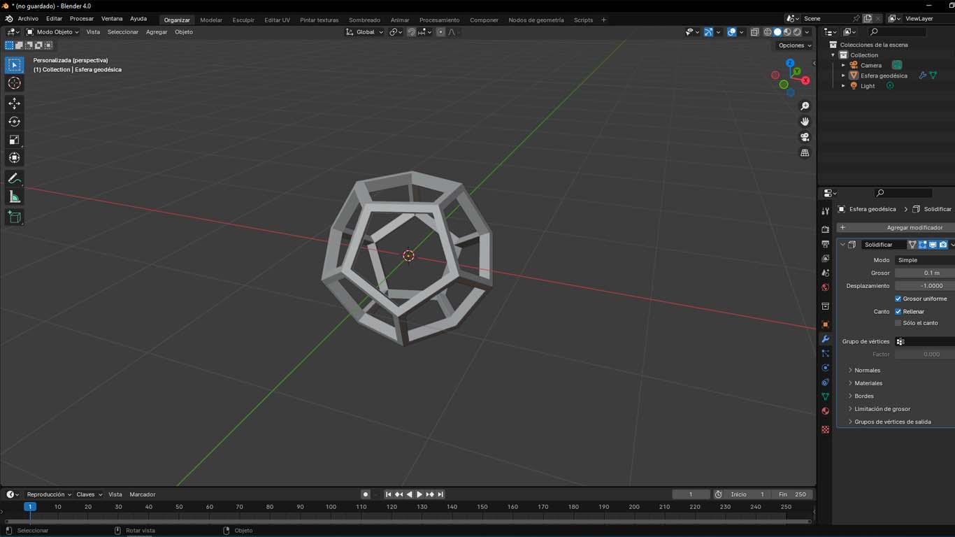
Then we select the achieved modeling and go to the bottom right where we will choose the MODIFIERS option where we will click and add a modifier and in this case we will select the SOLIDIFY option. Where we will modify the THICKNESS options and activate the UNIFORM THICKNESS option, here we can obtain the empty dodecahedron with its compact edges.
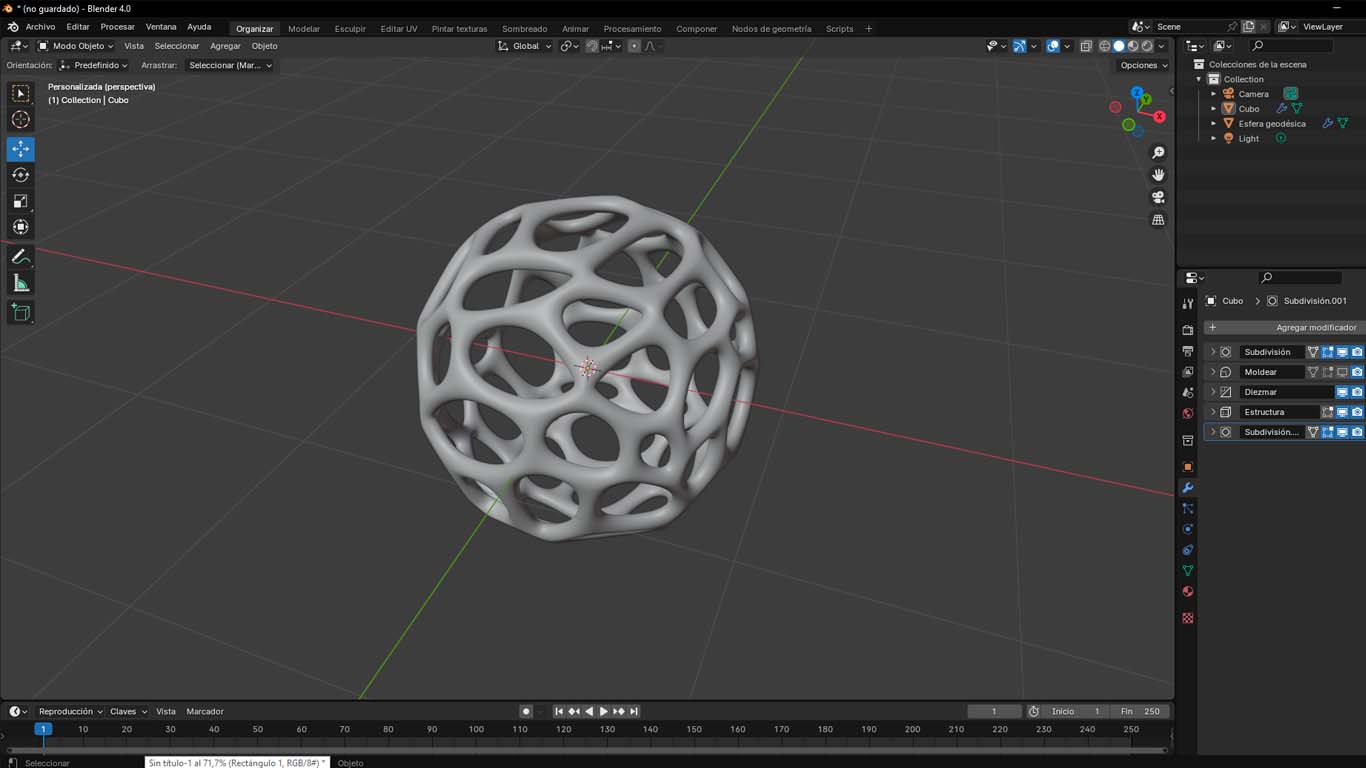
MODELING A VORONOI SPHERE
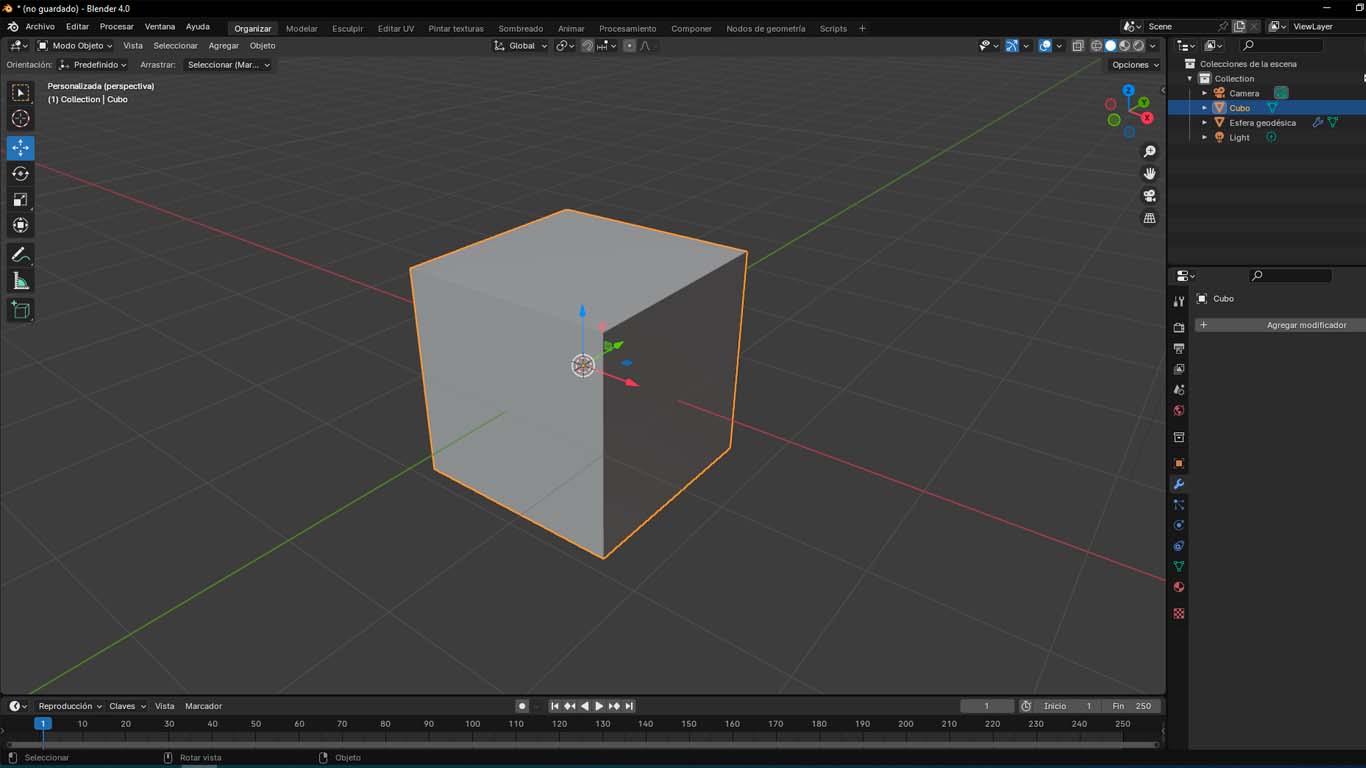
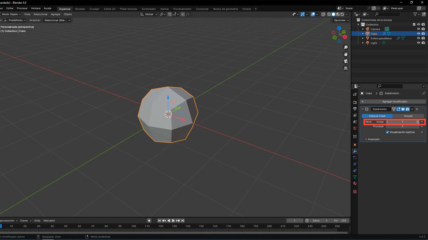
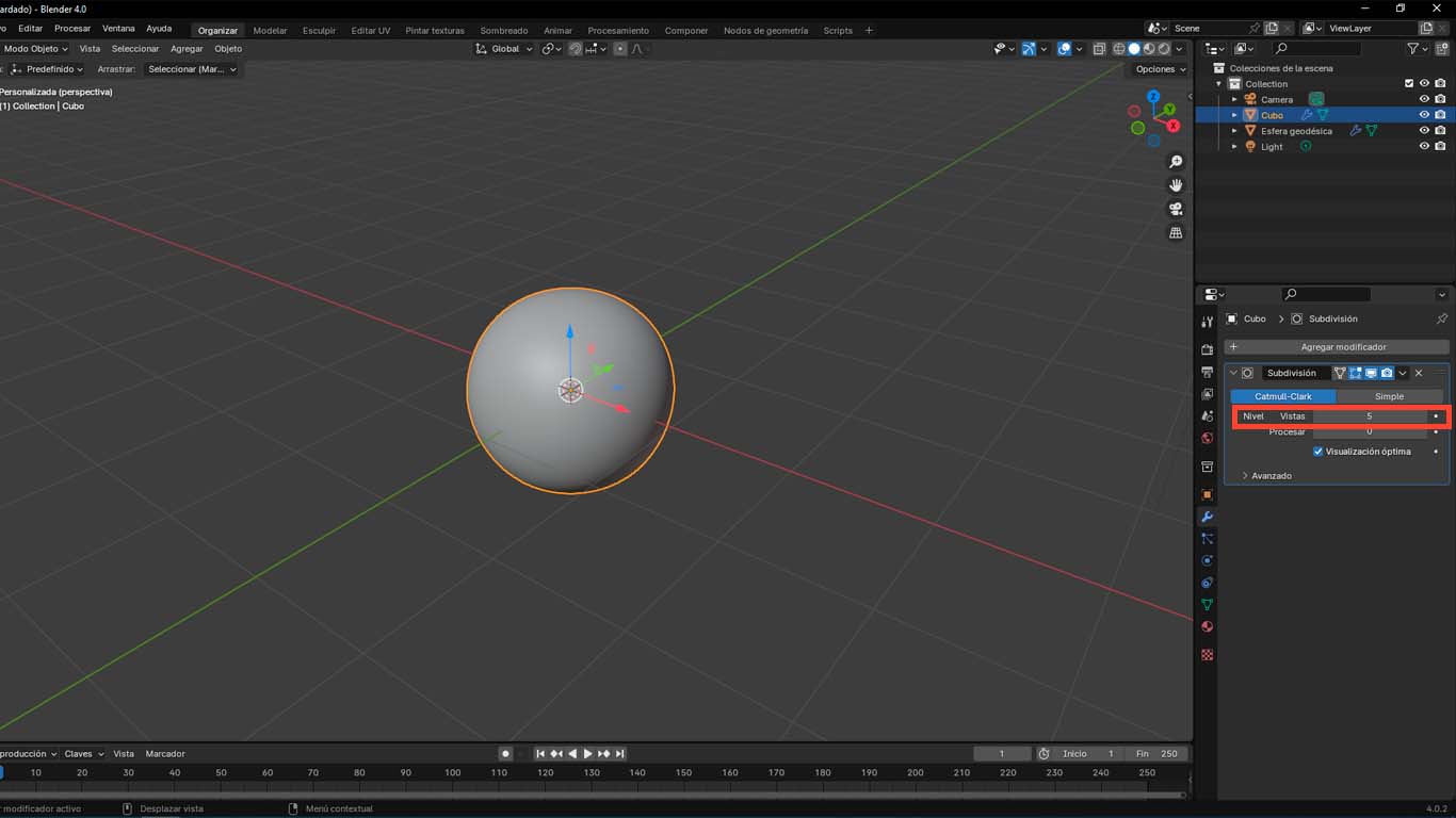
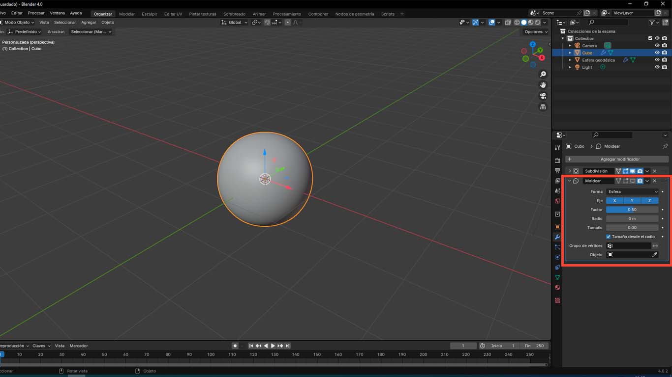
To develop the VORONOI SPHERE we add a cube in Blender and add a MODIFIER called SUBDIVIDE SURFACE where we change the VIEWS option from value 1 to 5 to obtain a sphere.
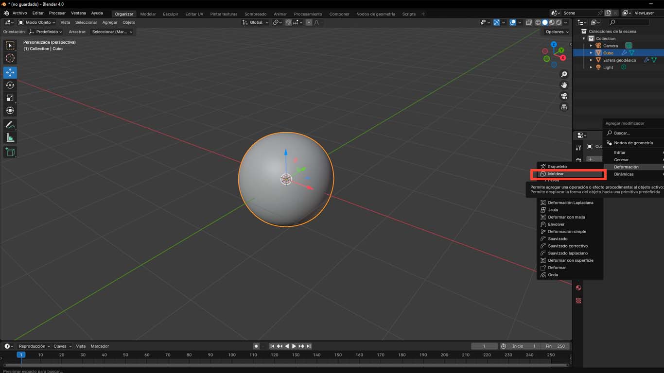
Then we add another MODIFIER called MOLD that we leave by default the configuration provided by the program.
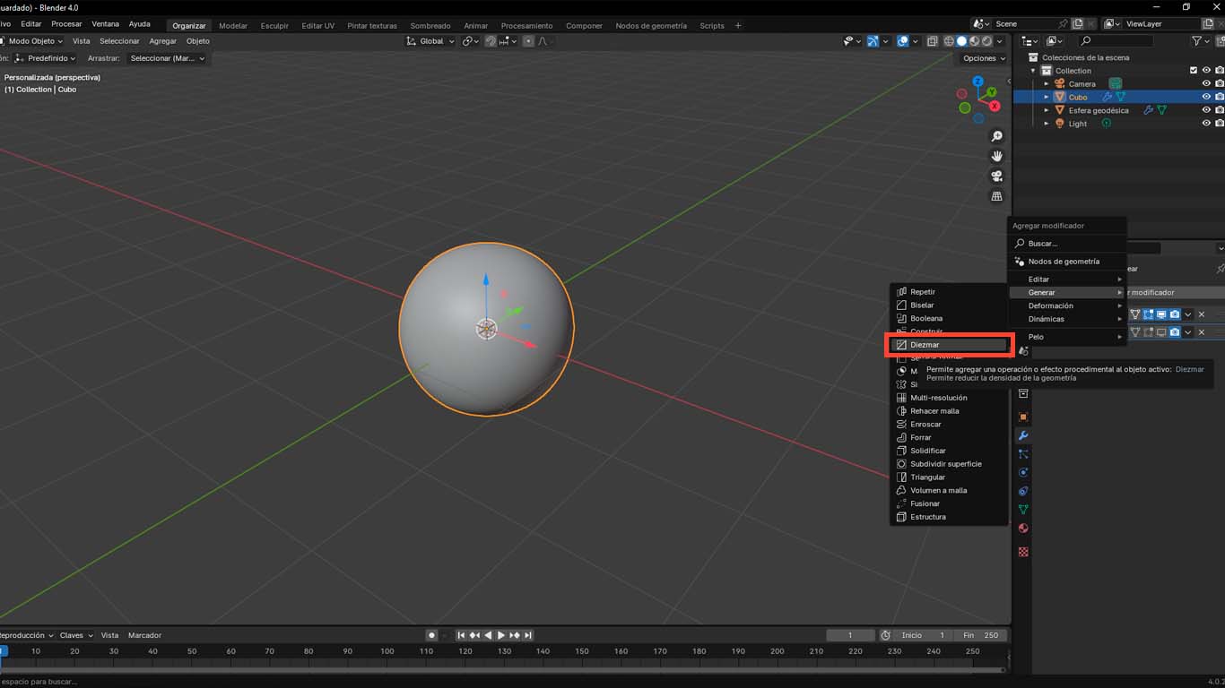
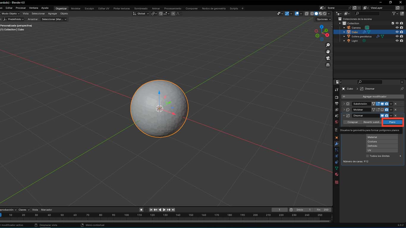
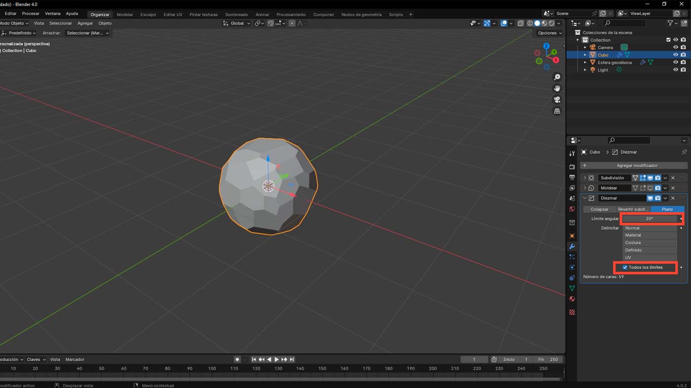
Then we add one more modifier called DECIMATE , where we activate the PLANAR option and change the ANGULAR LIMIT from 5 to 20° and finally we activate the ALL LIMITS option
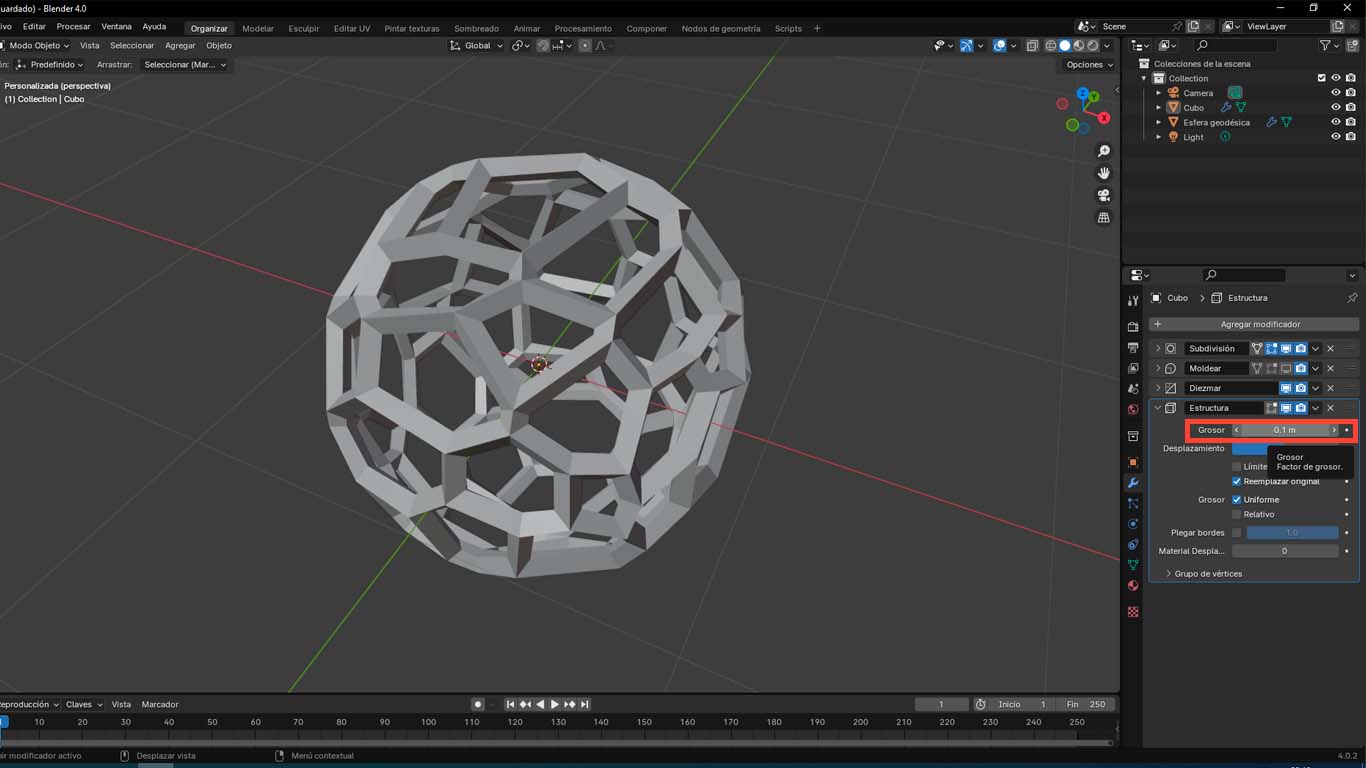
We add another modifier called WIREFRAME where we change the THICKNESS option according to what we want to achieve.
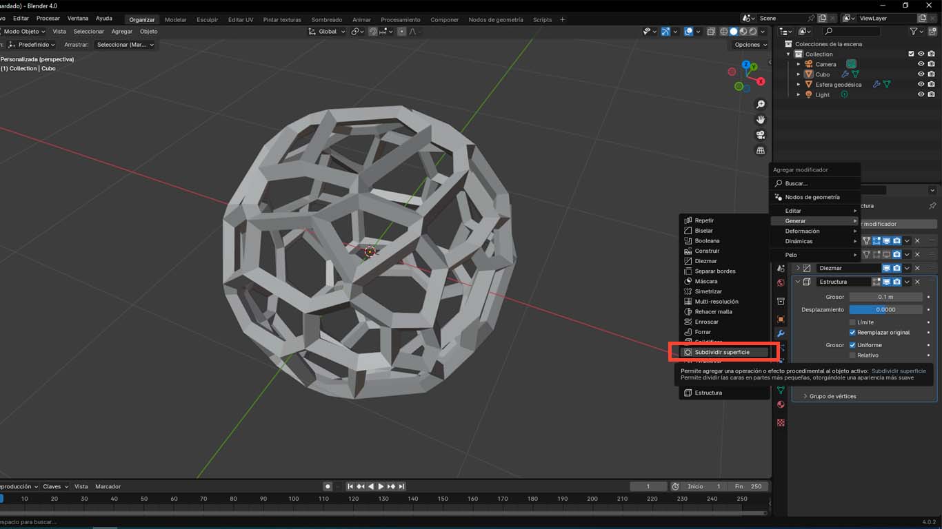
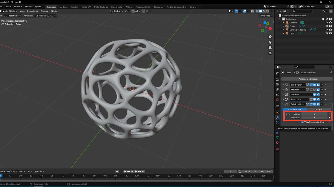
Finally, we add another modifier called WIREFRAME where we change the THICKNESS option according to what we want to achieve and we change the VIEWS and PROCESS options to achieve more detailed modeling.
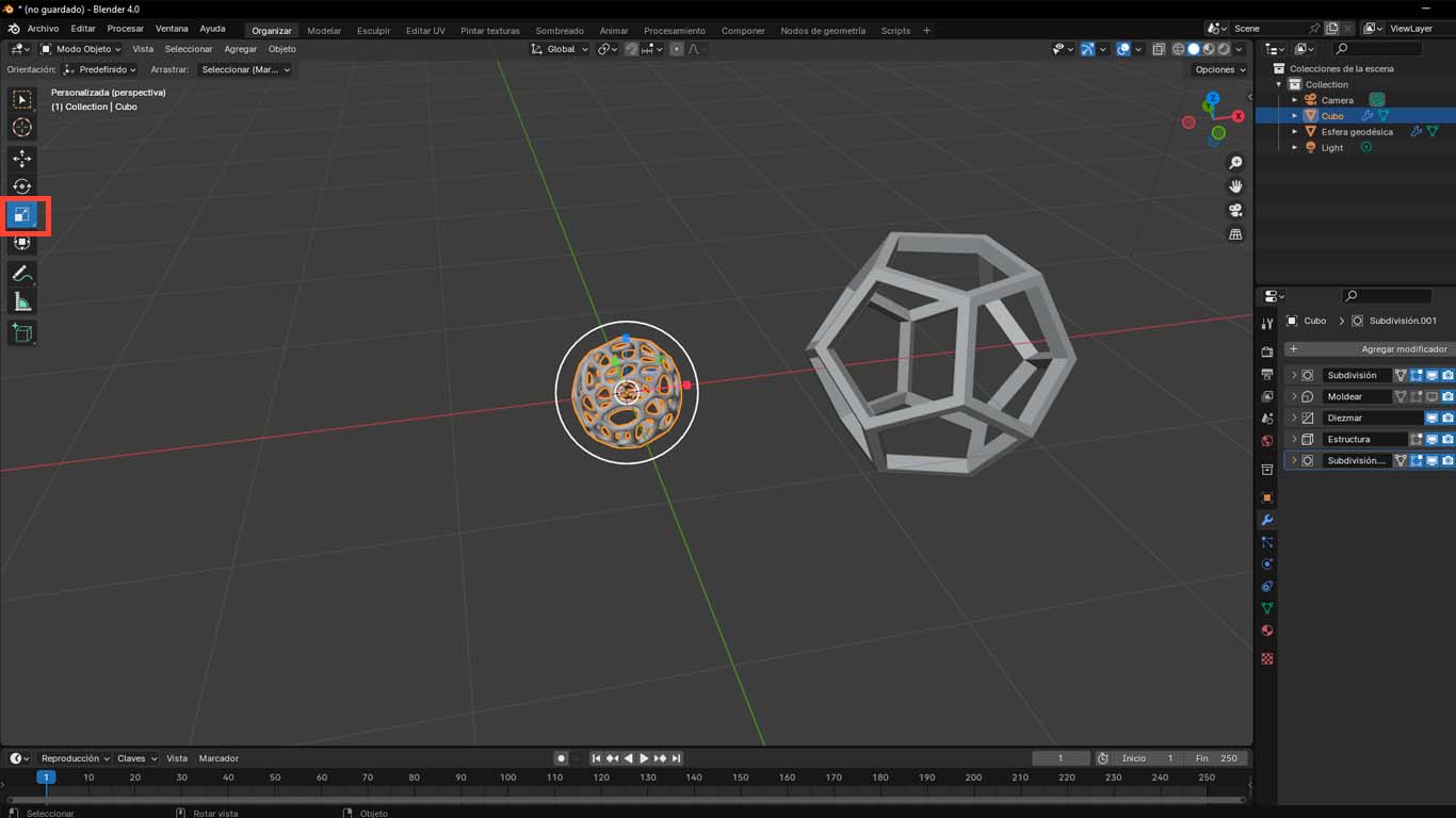
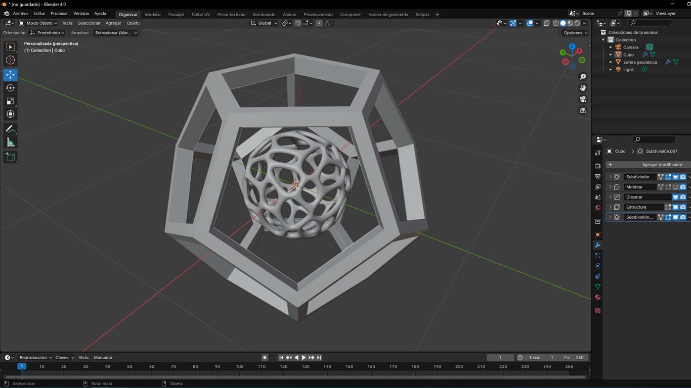
MODELING TO PRINT IN 3D
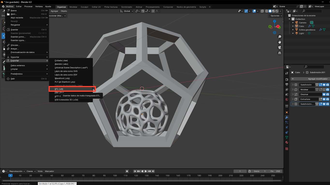
After modeling the 2 designs, I decided that the sphere should be inside the dodecahedron, so I scaled it until the size of the sphere could not come out on one of the sides. The idea is that it stays inside the dodecahedron and can move. Likewise, we place it at the bottom so that when printing it can be modeled and finally we export it in STL format to the PRUSA program.
PRINTING 3D MODEL
CONFIGURATION IN PRUSASLICER
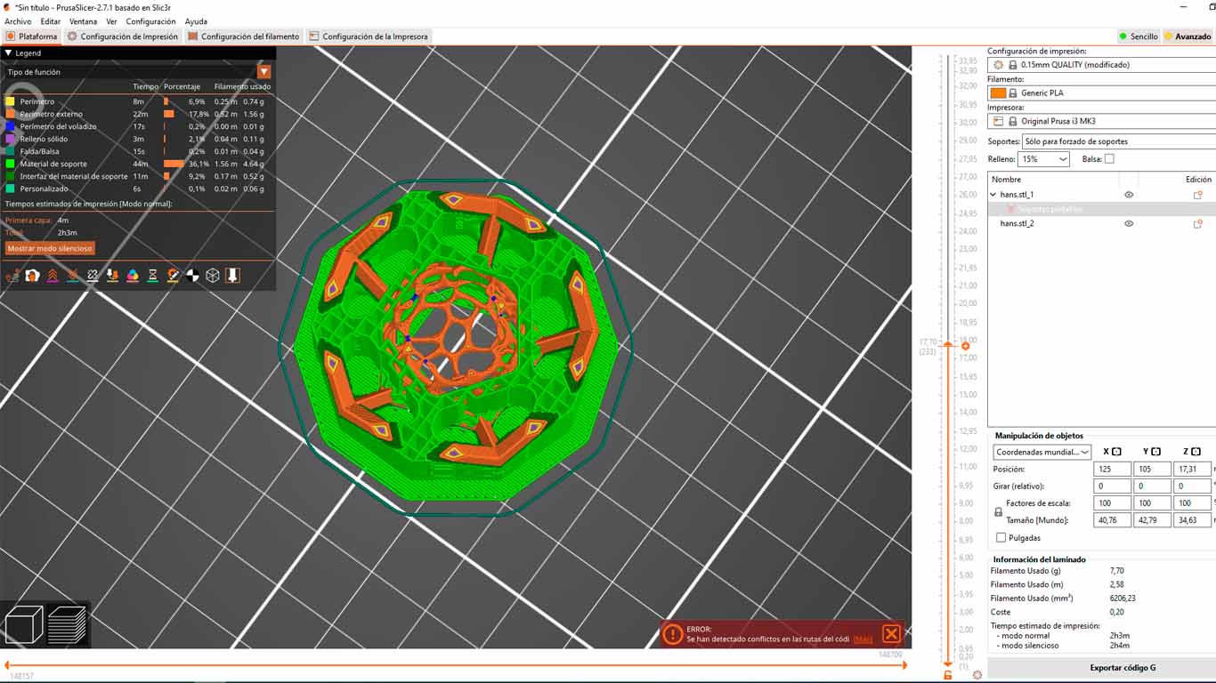
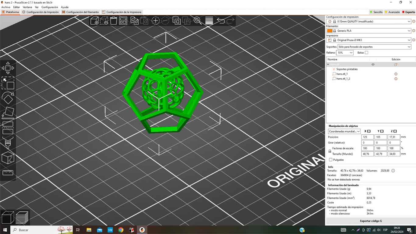
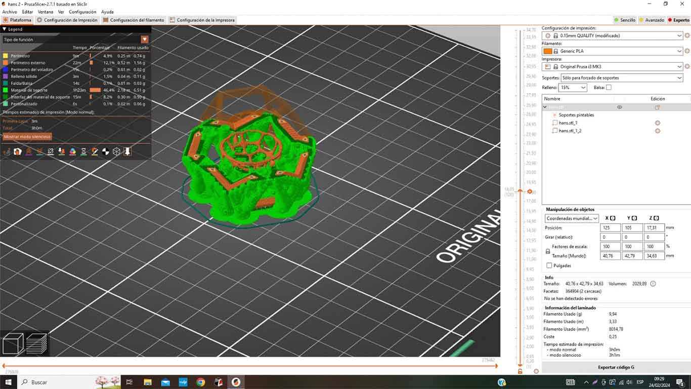
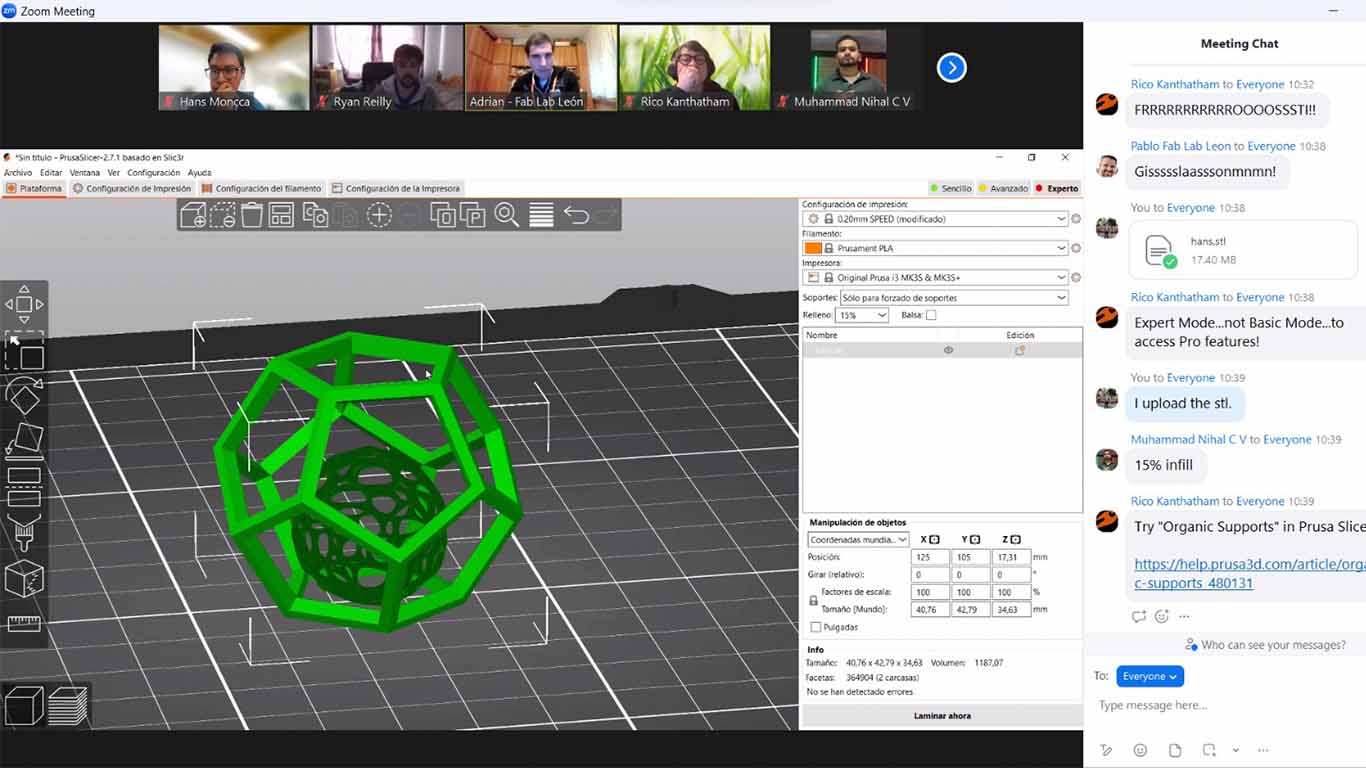
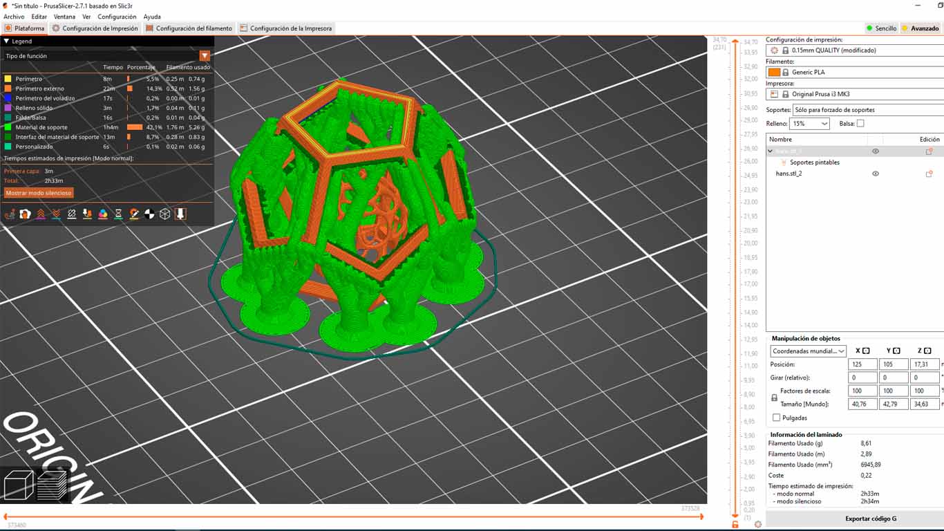
To start printing in 3D we have to import the modeling file into the PRUSASLICER program where we can see that the modeling does recognize both the dodecahedron and the sphere.
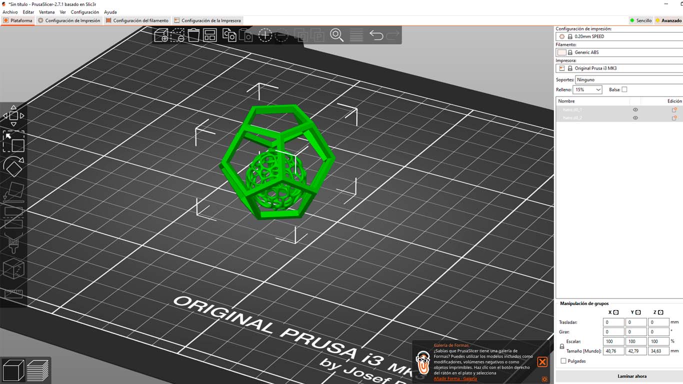
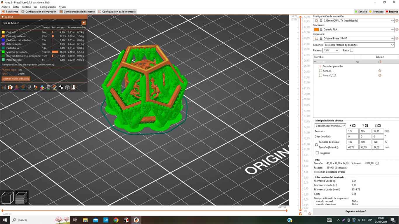
As it is a modeling that must meet the objective of the assignment, we have to generate SUPPORTS that the PRUSASLICER program itself provides us in order to develop complex modeling that does not present any basis. Therefore, for the first attempt, the ADJUSTED type supports were used but only for the dodecahedron since we cannot generate supports inside the sphere since it will be difficult to remove and the idea is that it is empty inside.
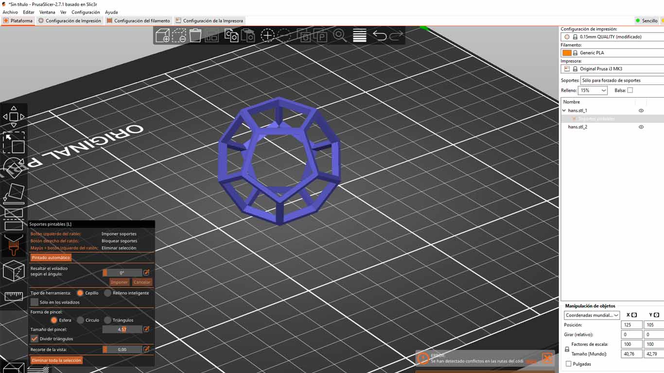
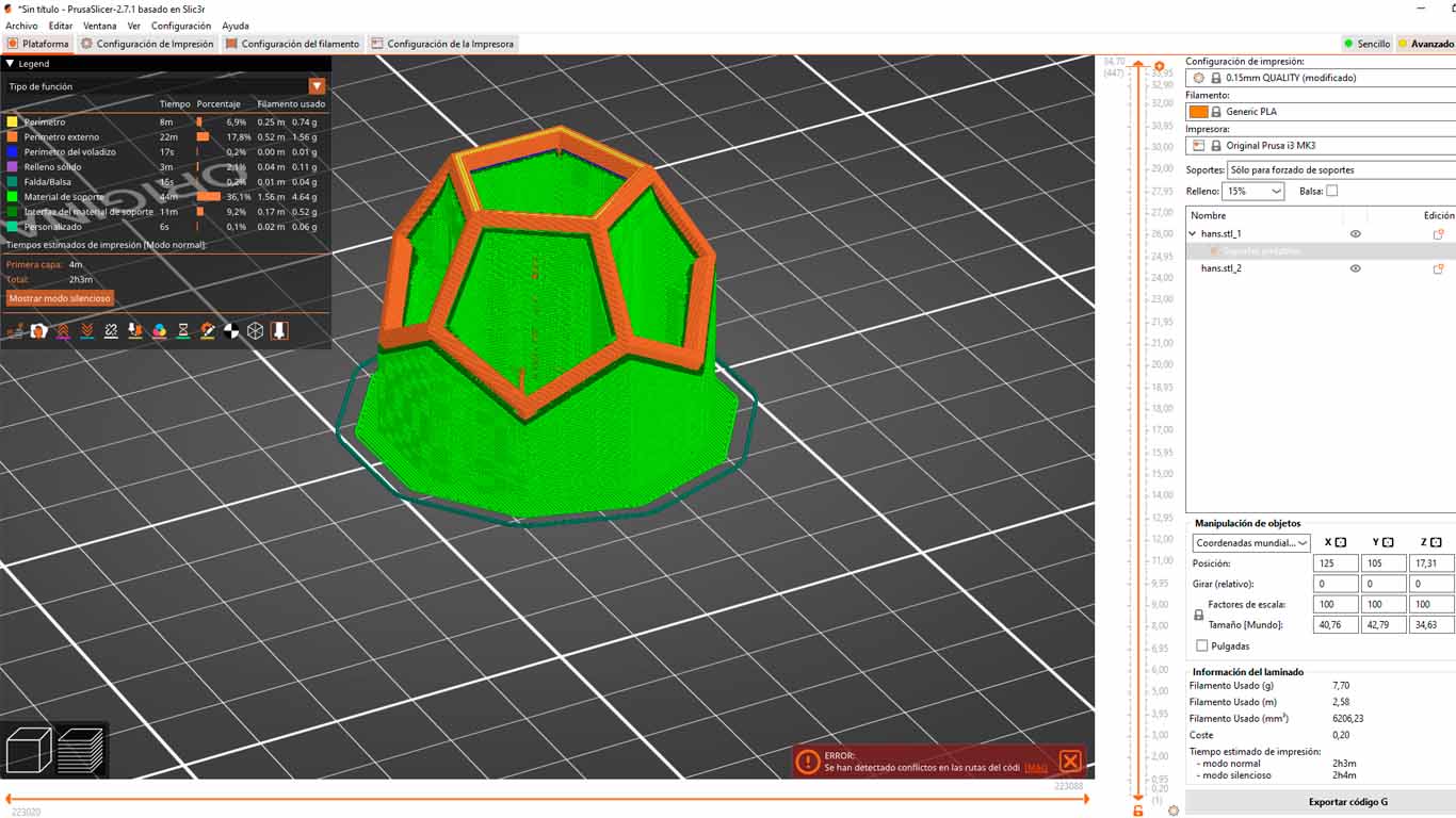
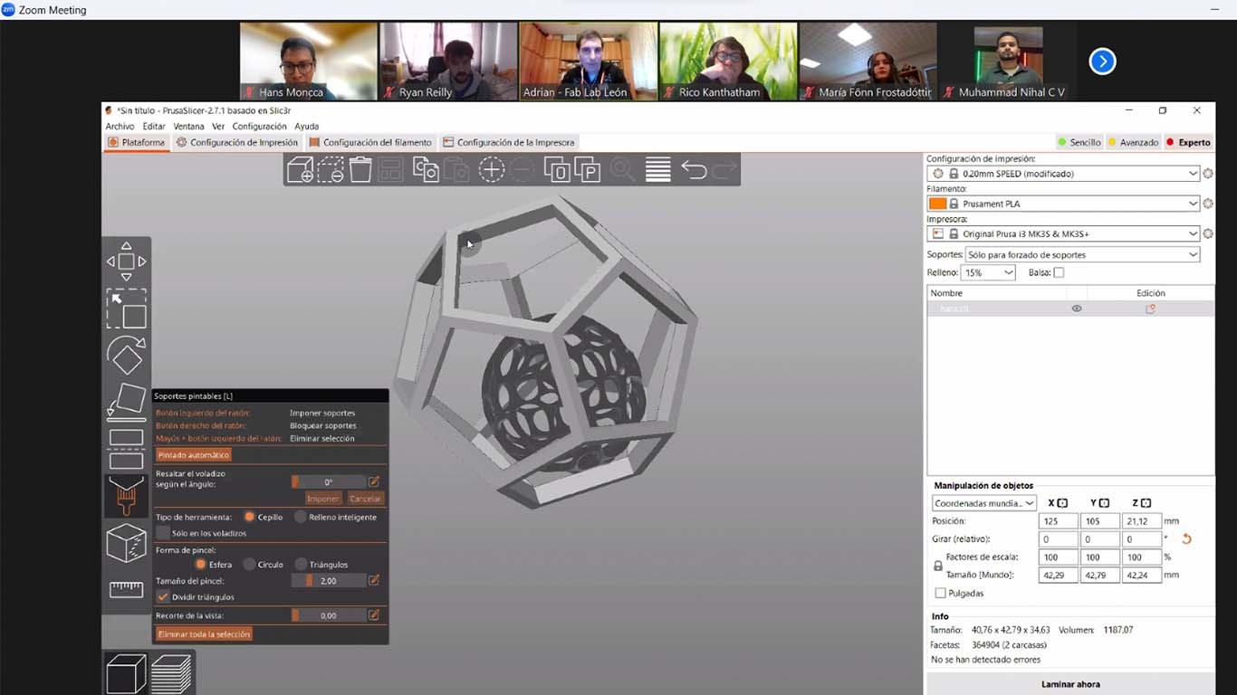
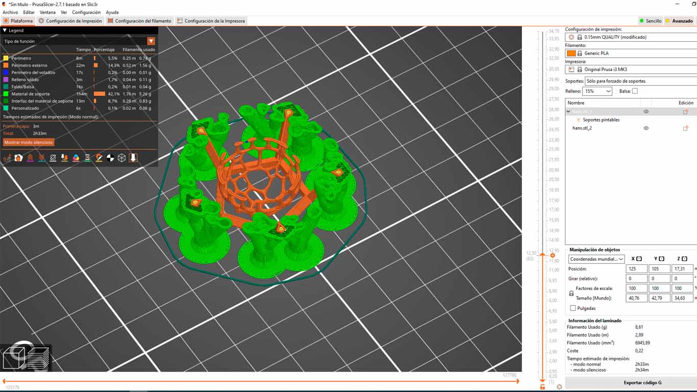
We can see that the inner sphere does not have any support inside, after configuring the printing, we send it to print.
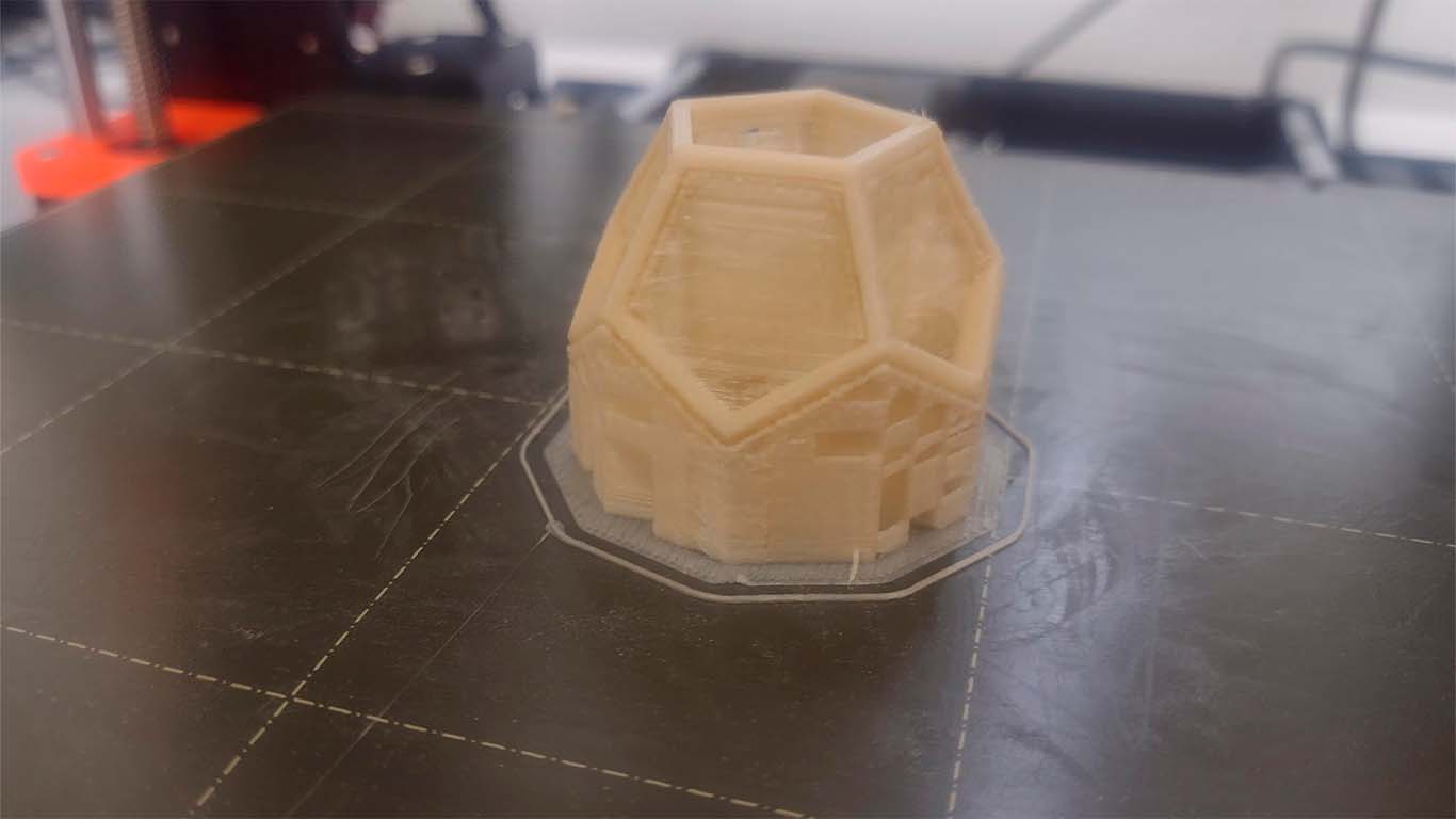
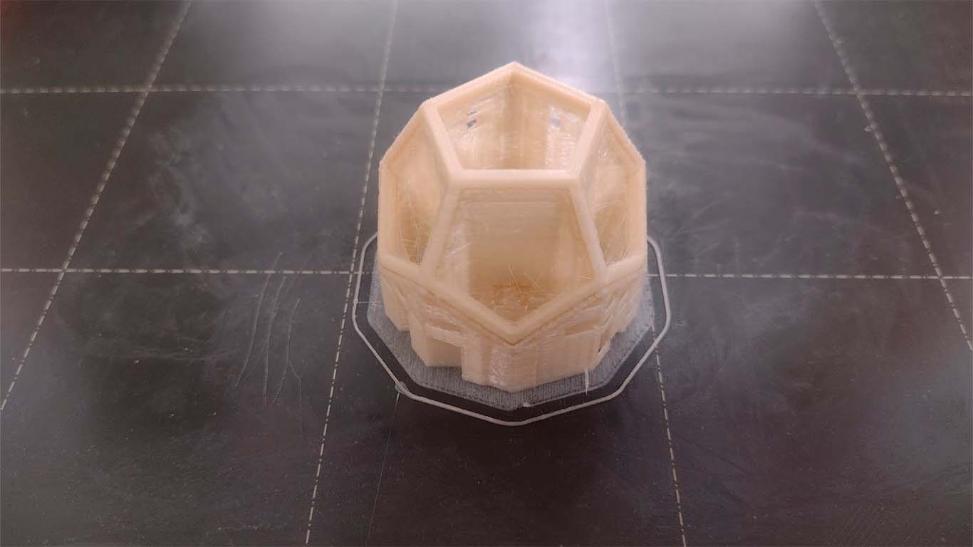
3D PRINT - TEST 1
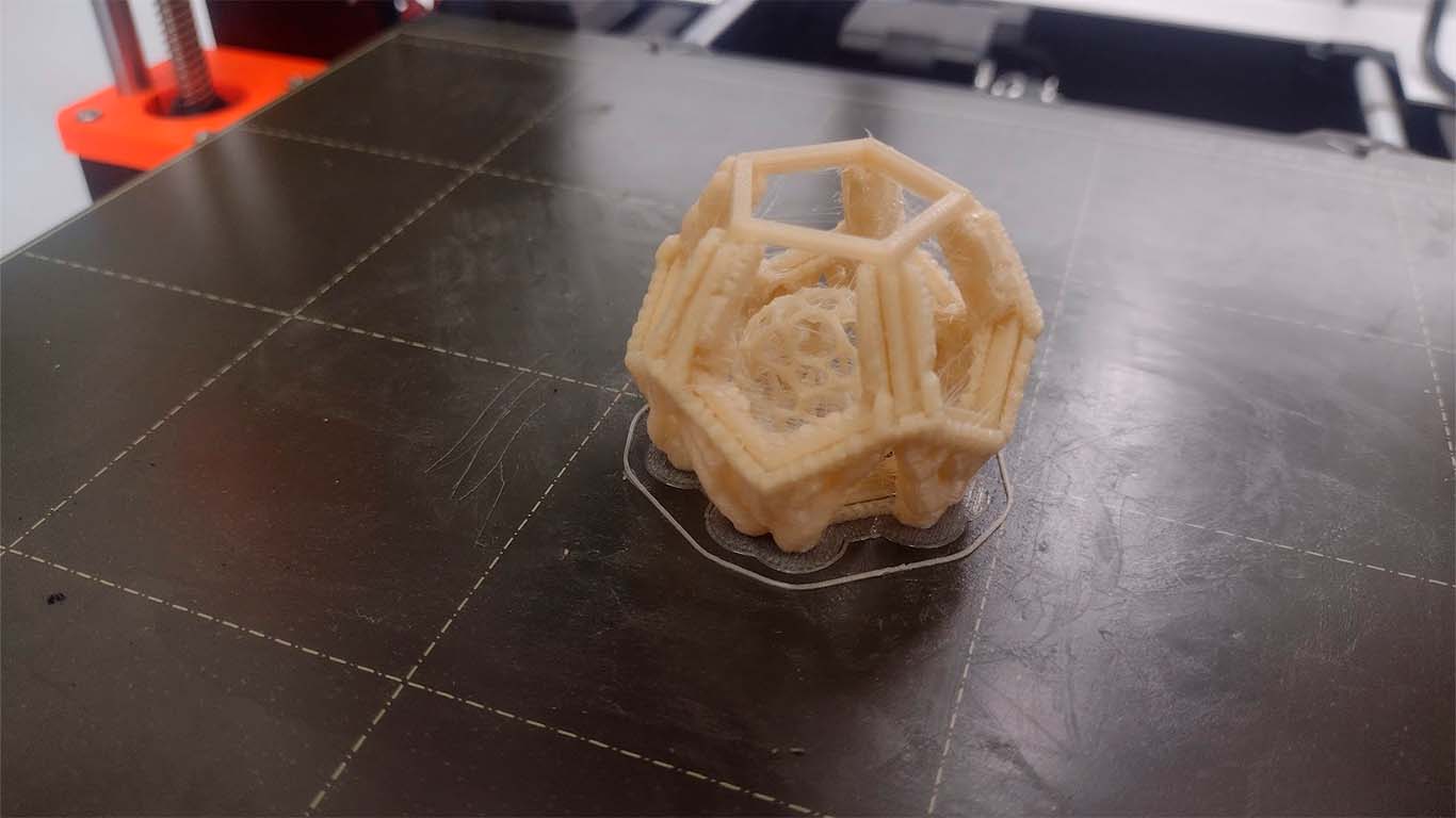
For the first test, the printing was bad because the base of the sphere did not develop correctly, where it has a part that the printer could not make. Also, when removing the supports it was a bit complicated and broke an edge of the model. My friend Maryori told me that she should try another type of support since it is very difficult to remove those types of supports and she recommended the ORGANIC.
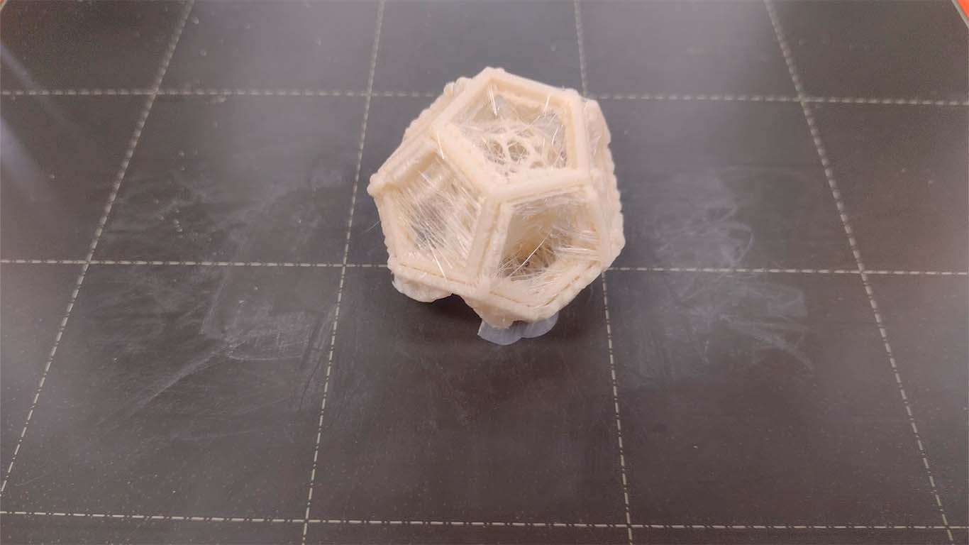
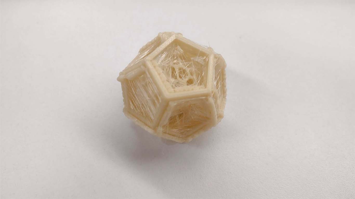
3D PRINT - TEST 2
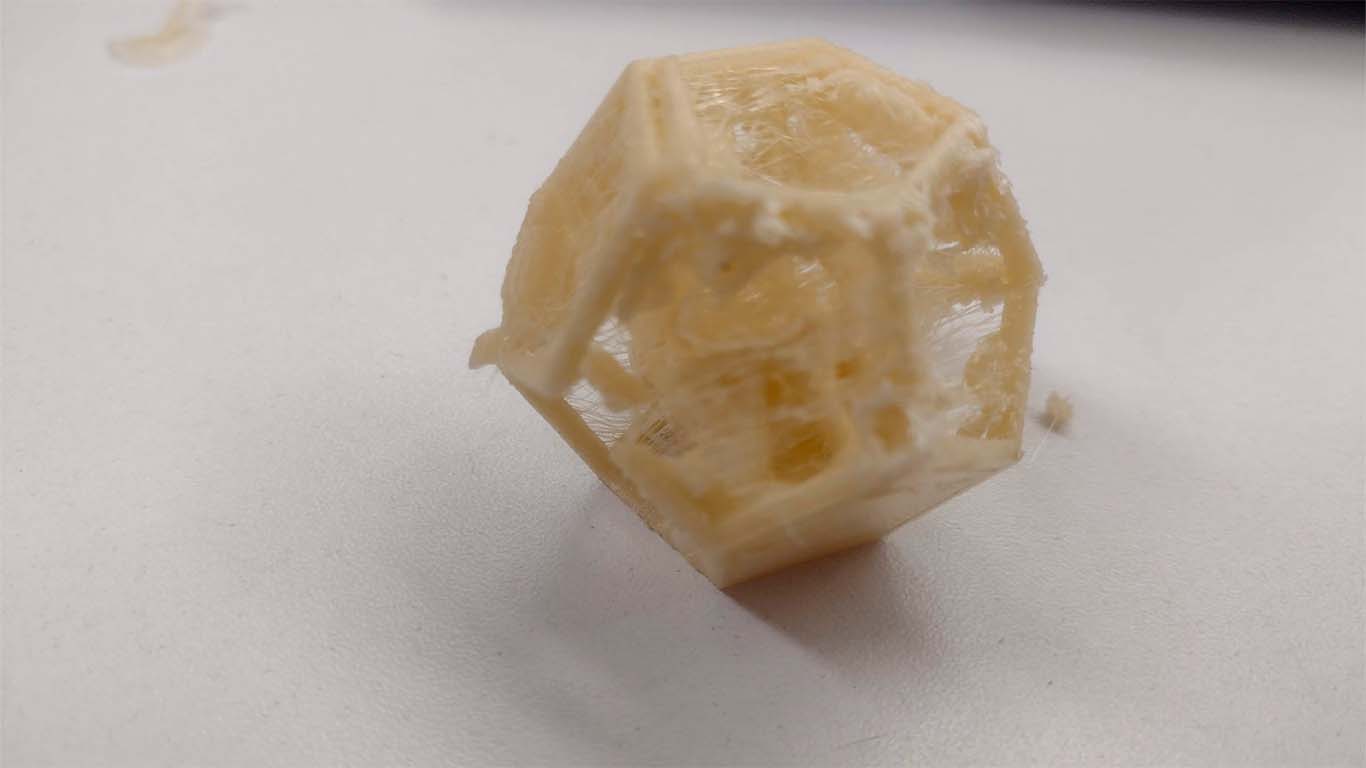
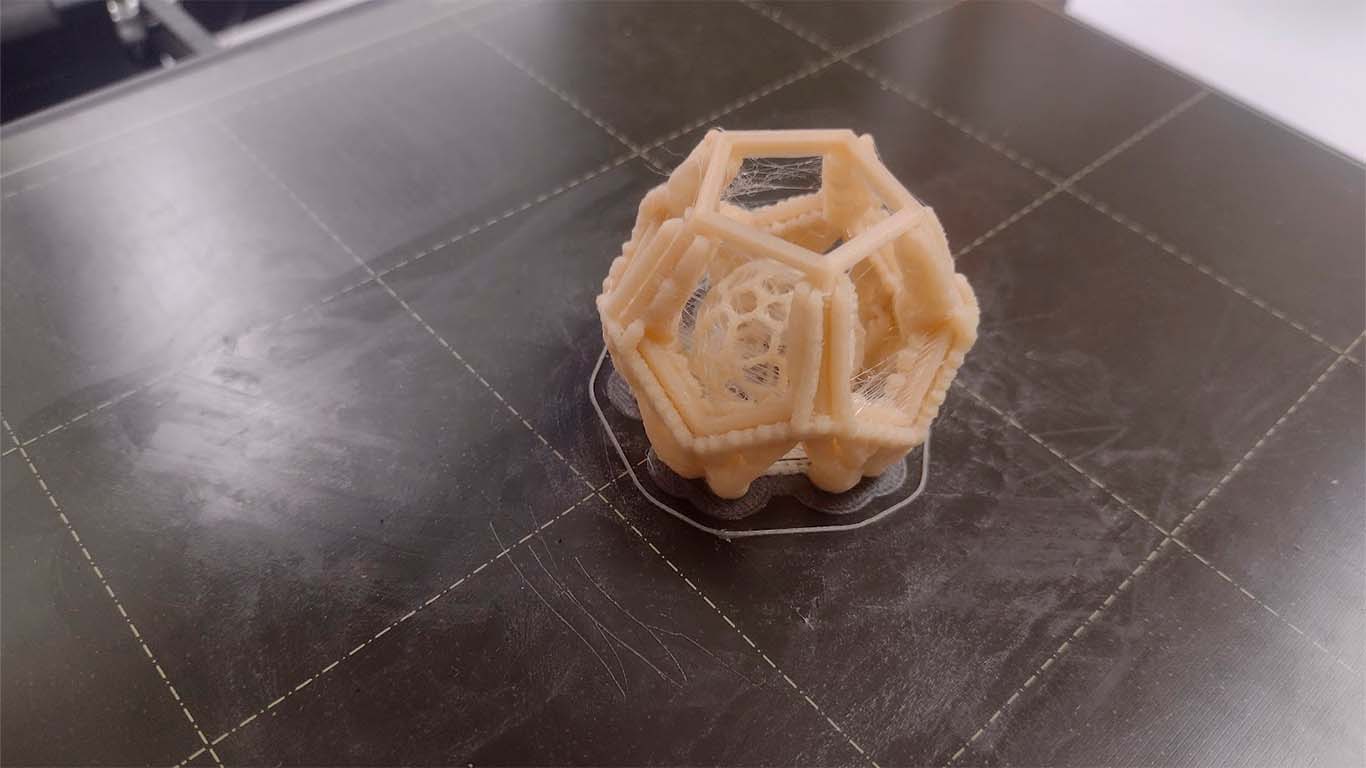
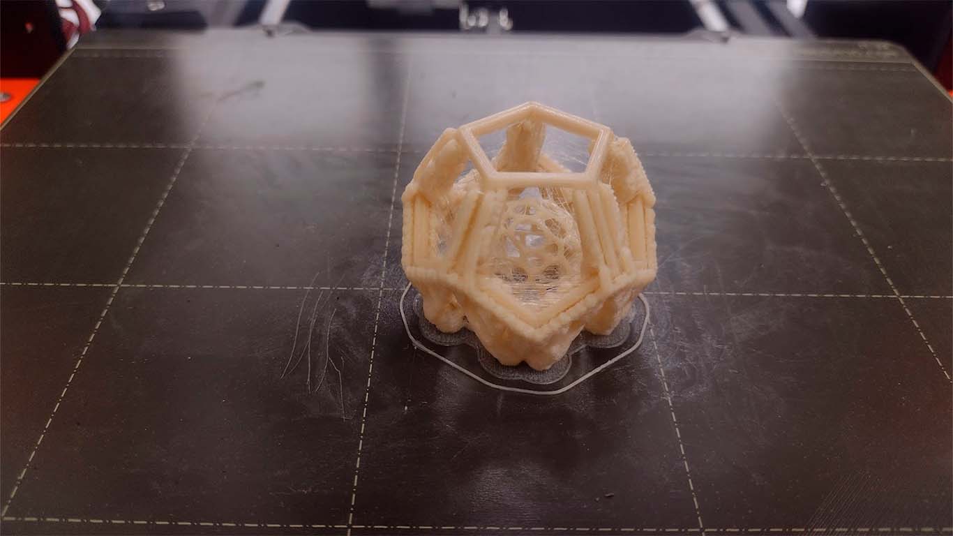
For the next test I decided to use the ORGANIC type supports on the dodecahedron and the sphere, which was a recommendation from my friend Maryori. I decided to put the supports on both models, I raised the sphere so that it has a base and from there the impression can be developed without losing any side like the previous test. But I think that by letting the software make the supports by default, the impression came out very well but when it came to removing the supports it was impossible and worse in the sphere. Here my results:
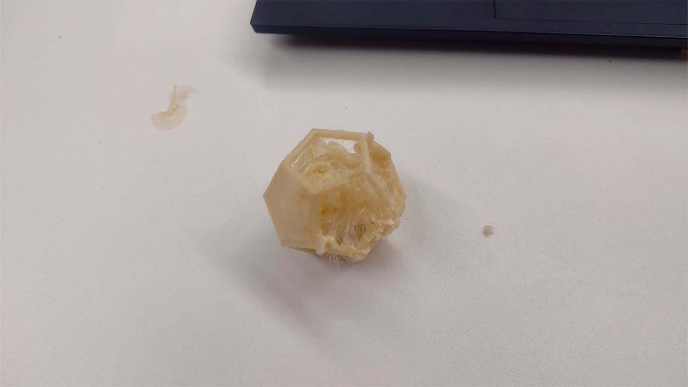
The 3D printer did its job of making the model, but it had many threads of filament and all the supports were difficult to remove. While I was doing the work of removing them, the model broke again and I got very frustrated by how long the printing took, but I will continue learning from it.
3D PRINT - TEST 3
On Saturday 02/24 I decided to enter the OPEN GLOBAL TIME where Adrian and Rico gave me the opportunity to tell them about my experience about the supports in order to achieve the impression of the modeling and they helped me to better understand the tool that the PRUSASLICER gives us on the supports and it helped me a lot to understand and get my modeling printed. I felt that now I would achieve it thanks to your support.
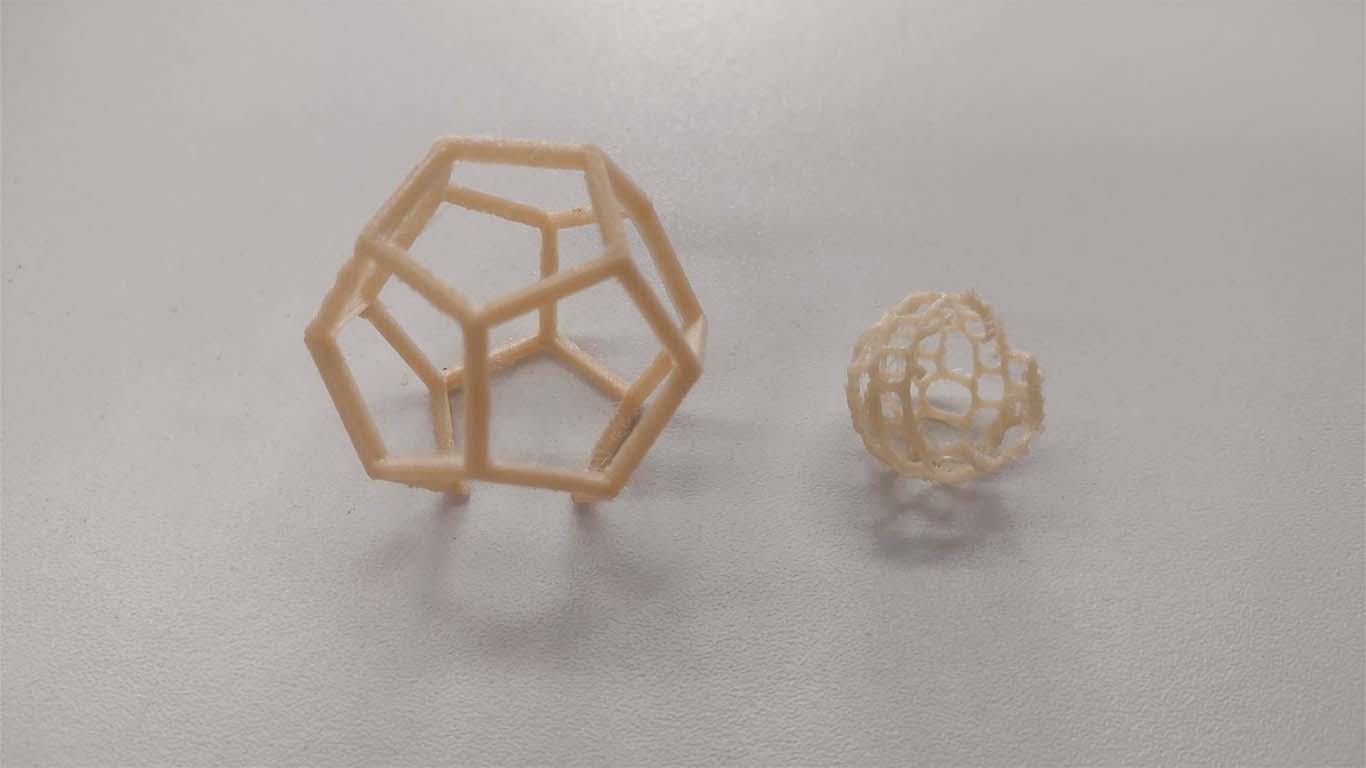
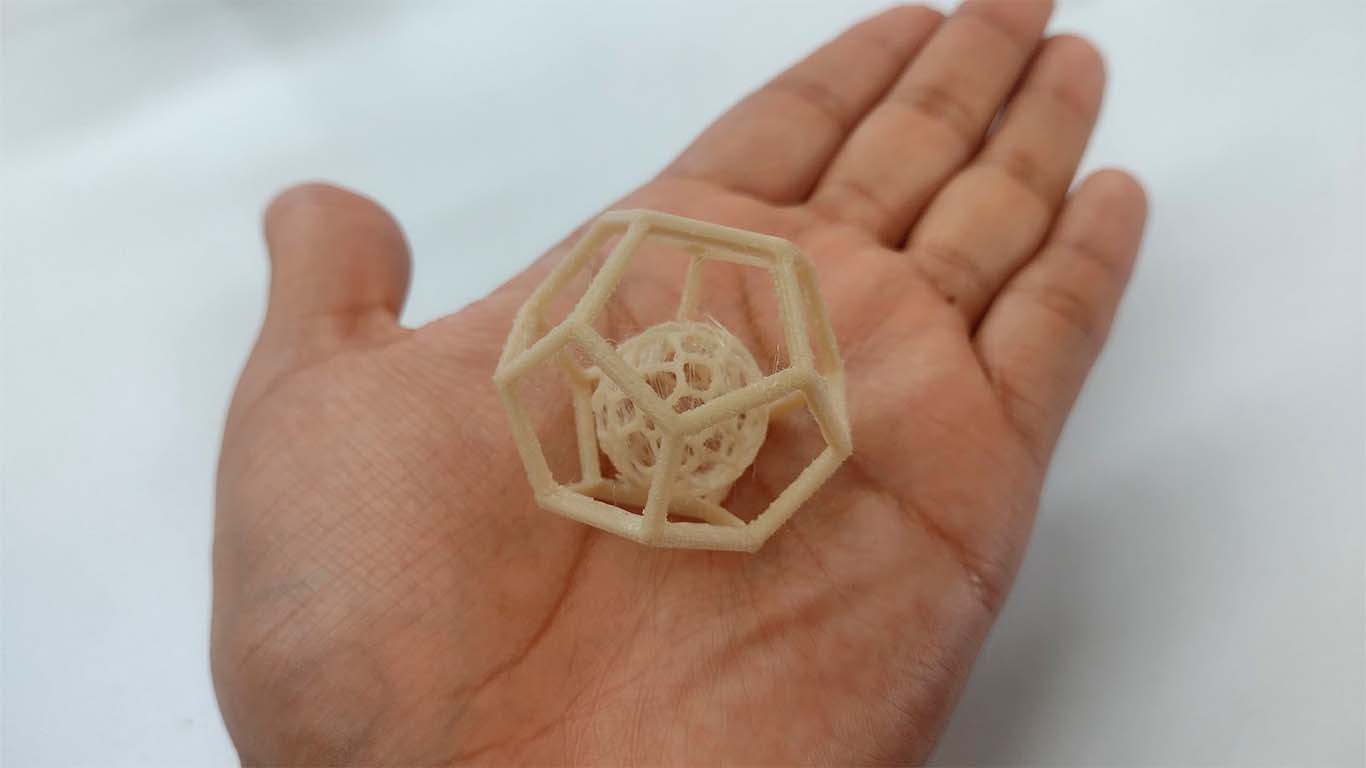
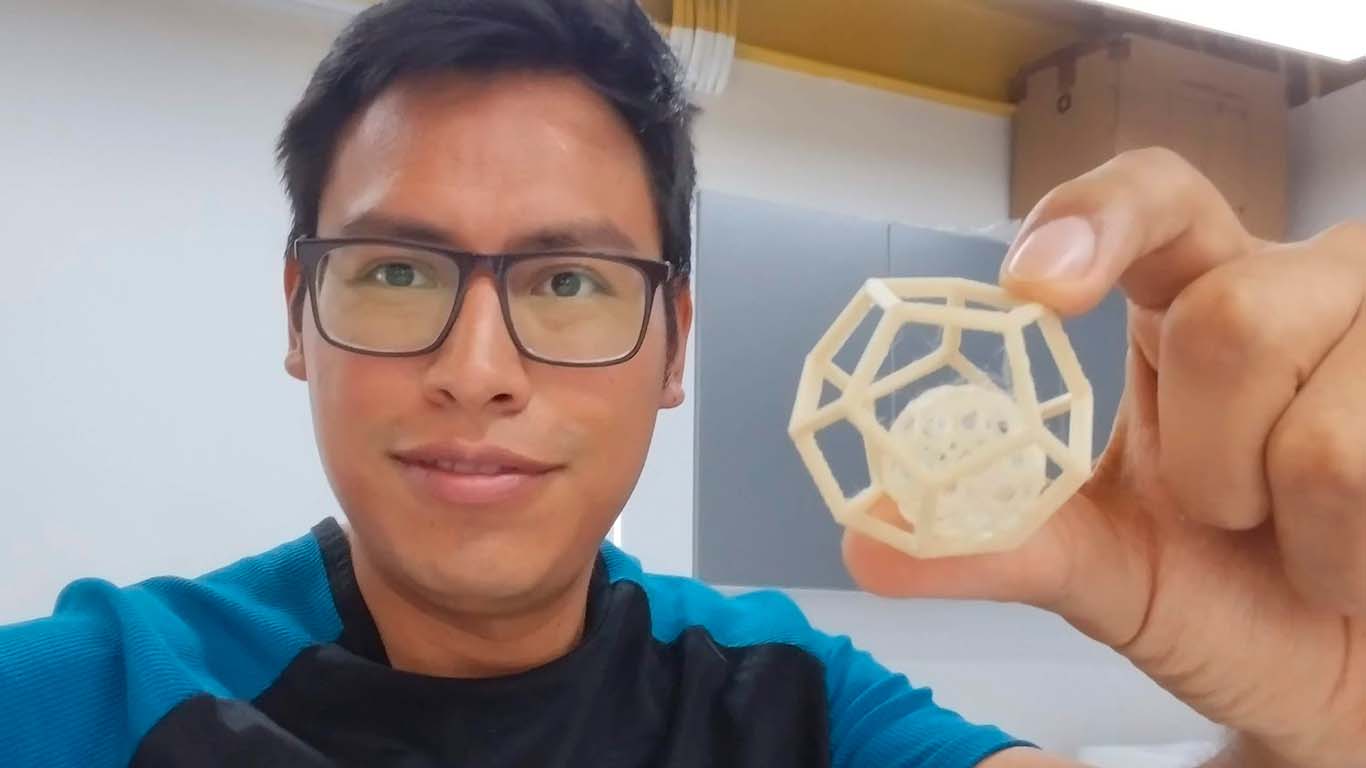
After understanding the tool and the recommendations that Adrian and Rico gave me, I began to work on the supports to achieve the print. The result came out very well, I was able to print and remove the supports without affecting the model.
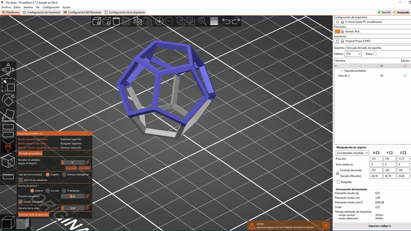
We must keep in mind that the supports should not obstruct or affect the modeling, that is why we have to review and place the supports only where they are necessary, to be more effective in time and to be able to achieve the modeling.
Here I show the photographs of the printing and the process of removing the supports. It turned out very well, a good job and thanks to Adrian, Rico and my friend Maryori who also helped me a lot to achieve the printing.
3D SCANNING
SCANNING WITH SMARTPHONE
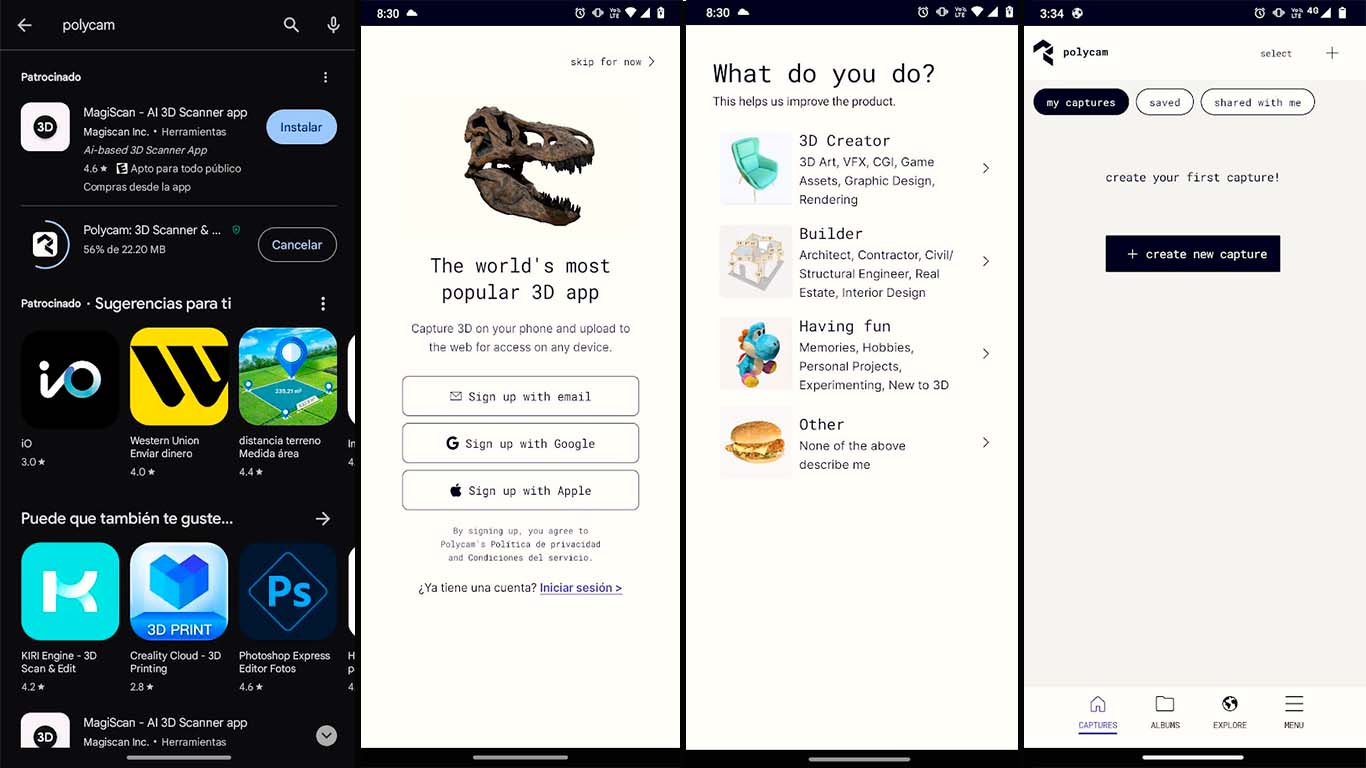
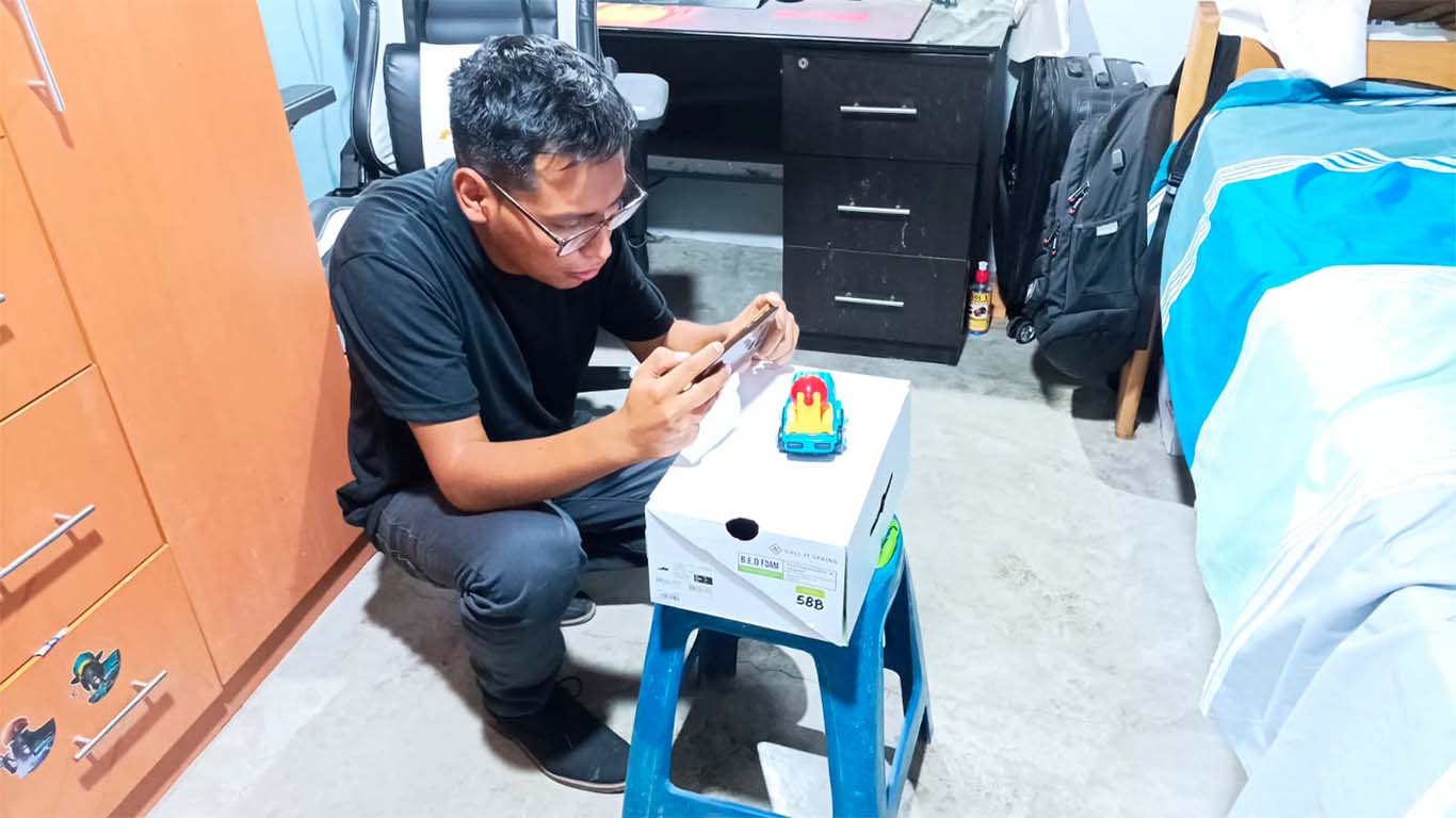
At the Scientific University of the South we still do not have a specialized scanner. Therefore, for the next assignment I am going to use my cell phone, which is a MOTOROLA G9 , and through the POLYCAM application I will scan a figure.
Installing POLYCAM is very simple, we just go to our PLAY STORE on Android and search for POLYCAM , where we install it and click CREATE NEW CAPTURE , where we will start scanning our object that we want.
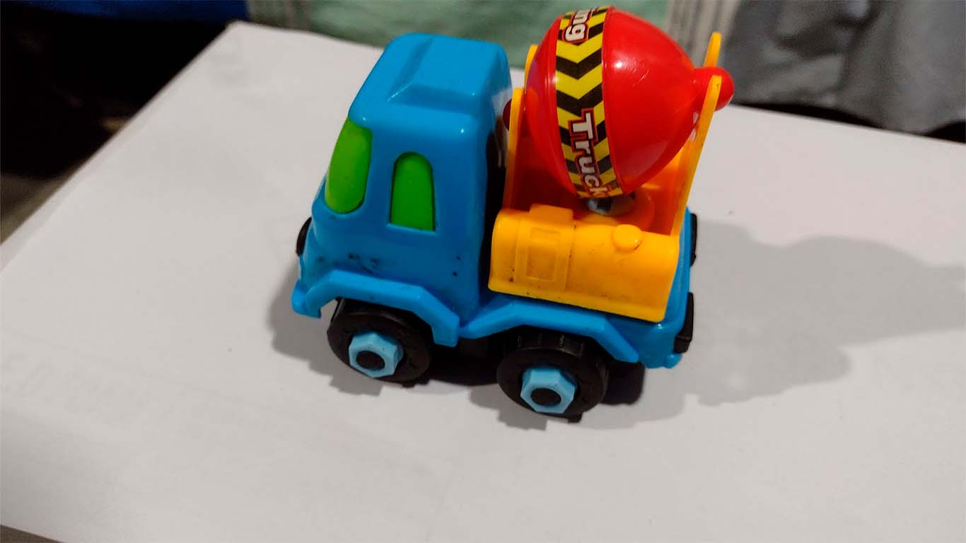
The object I chose was a toy from my cousin Fabricio who has autism, he loves his car because he takes it everywhere and it is always with him wherever he goes. I asked my cousin to borrow his cart so I could scan it since he is a very important person to me and I wanted to try with an object that has a lot of meaning.
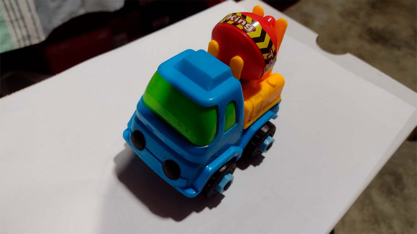
Previously, my friend Maryori told me about the application since she had used it and it was an application that they showed us in class as an alternative to using it. So I reviewed some tutorials on how to use it and started doing it. I relied on my brother and my cousin to help me with the lighting since it is very important when carrying out the scan and we figured out a way to be able to rotate around the object to be able to obtain all the views and the application to carry out its work.
The first scan didn't go very well because I did it very quickly and the application took very few photos to be able to do the modeling. Here I show the result.
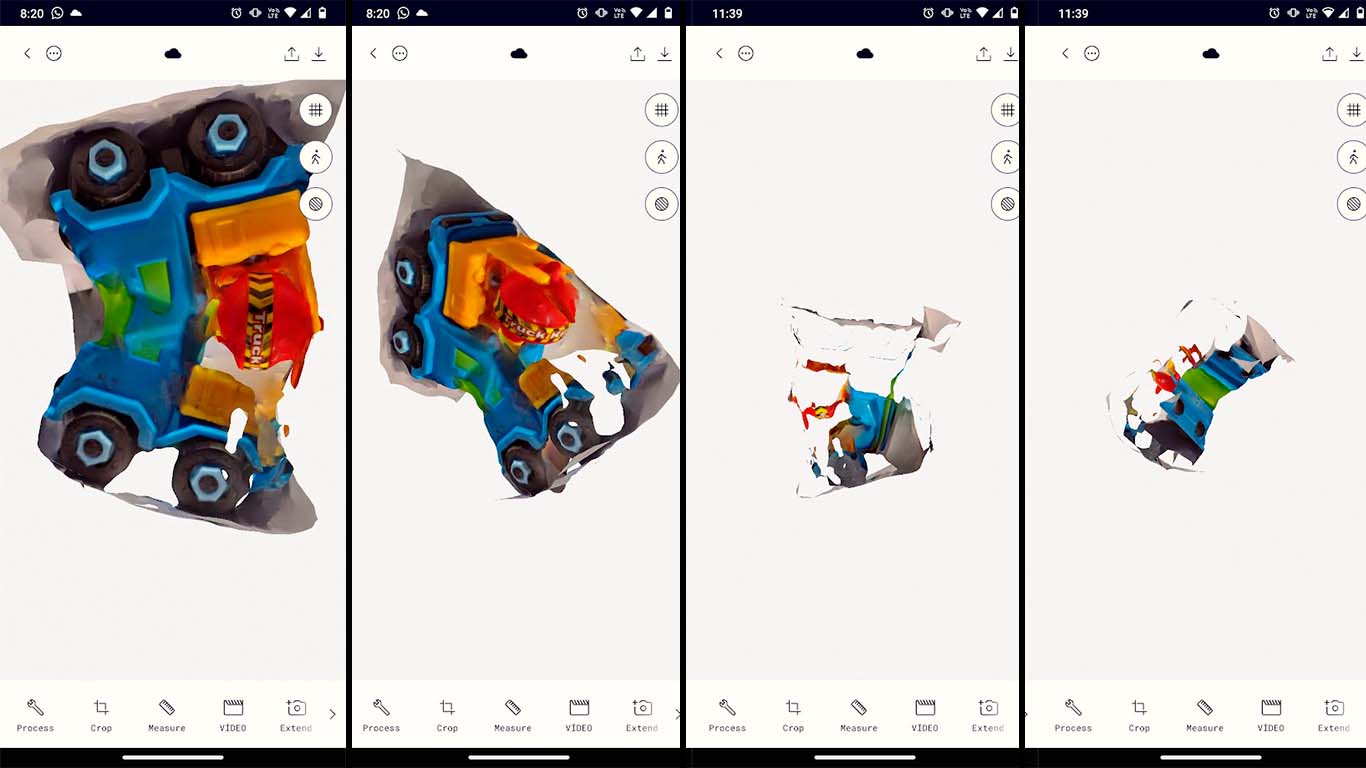
For the second test I was able to make a good scan since I rotated the camera more slowly and the application took approximately 80 photos, which is the ideal minimum. I had to wait a few minutes for the application to do its job and here I show you the result.
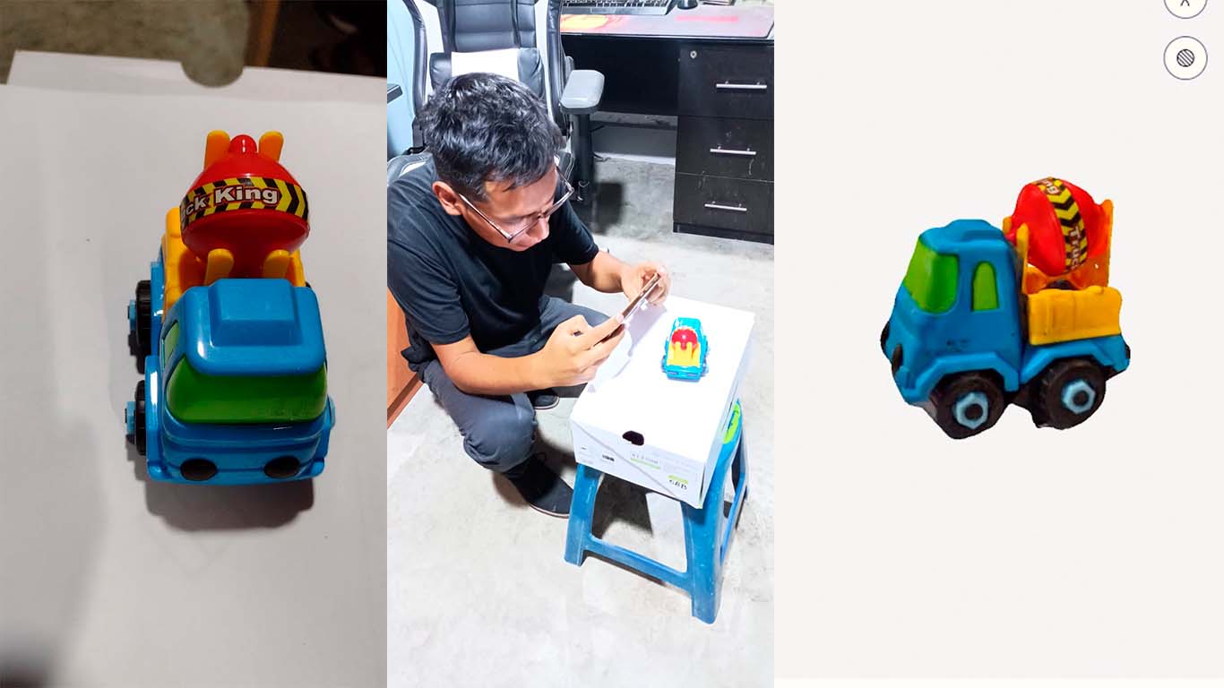
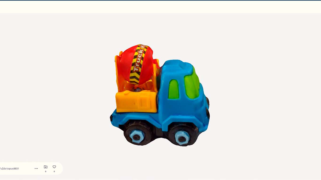
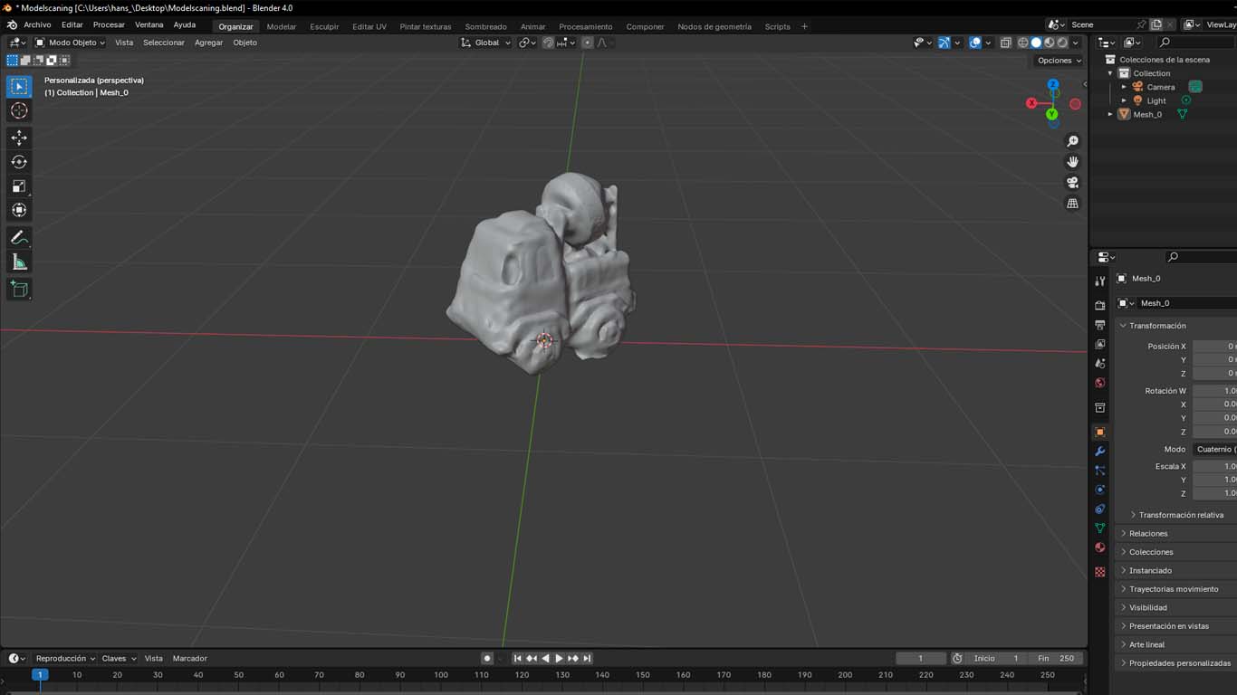
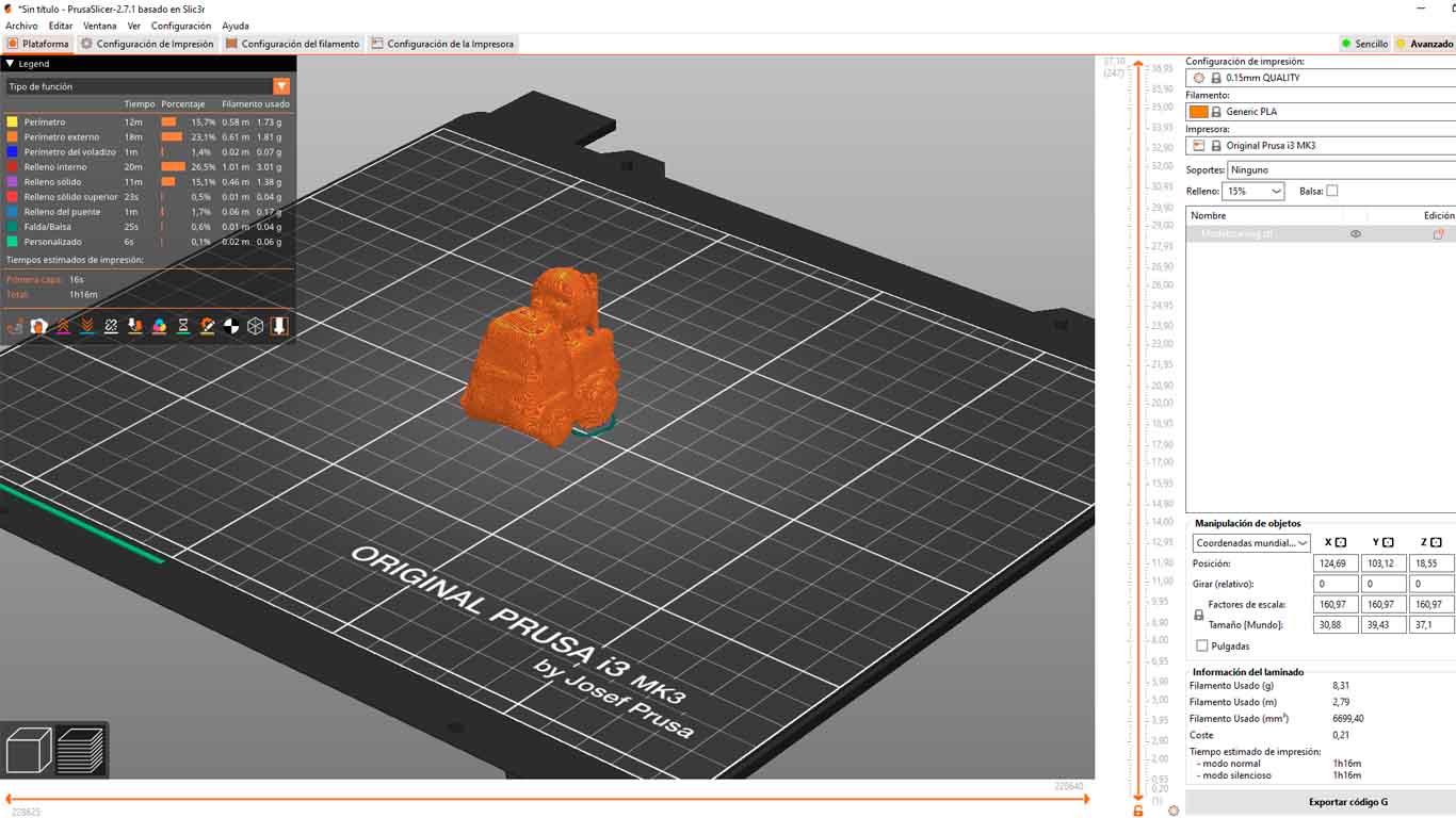
POLYCAM gives you the possibility of downloading the modeling that it scans in 3D OBJECT format since the other extensions are paid. However, we can obtain a good result from the modeling, here we can see what it looks like in the BLENDER program and then we can export it in STL format to be able to 3D print it. Here the results.
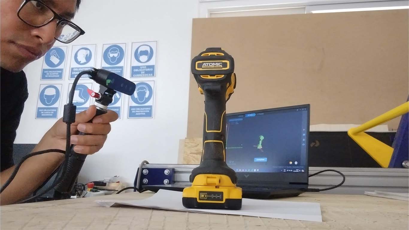
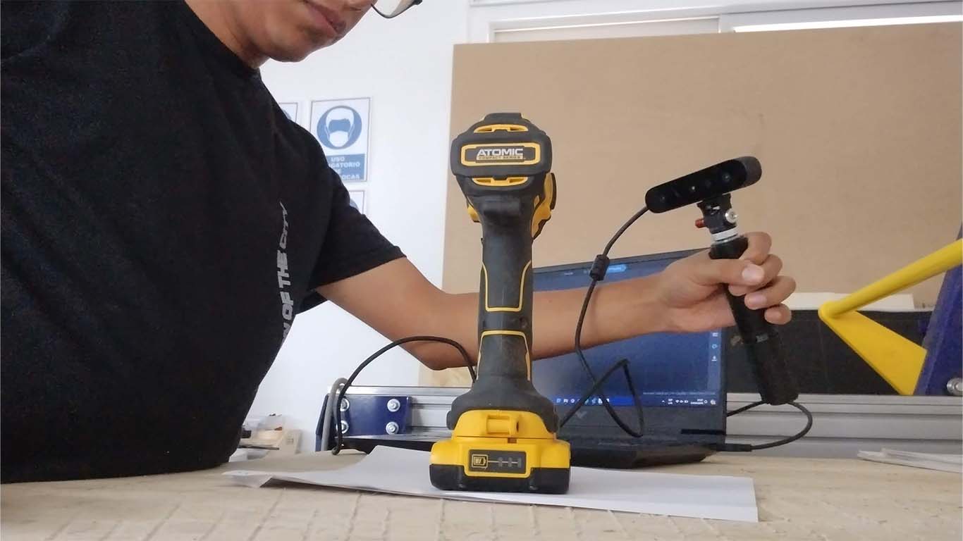
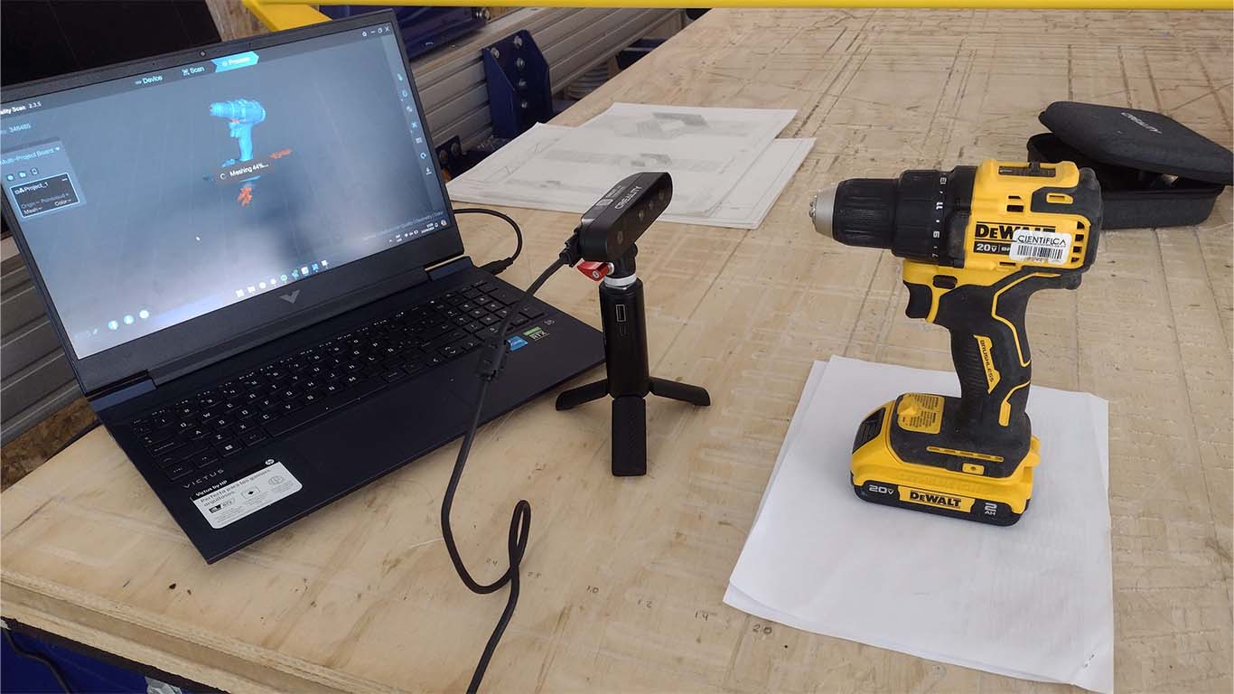
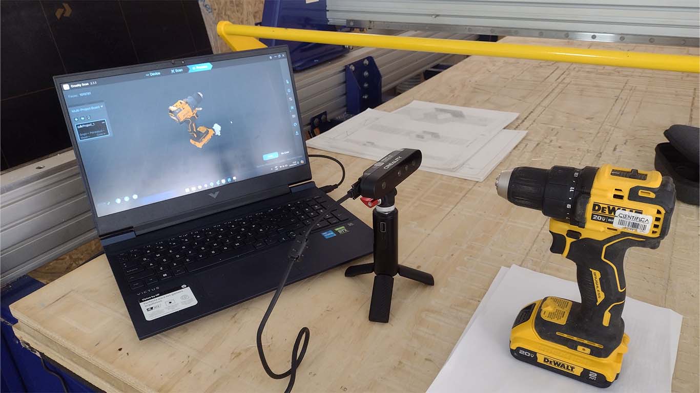
SCANNING WITH 3D SCANNER CREALITY
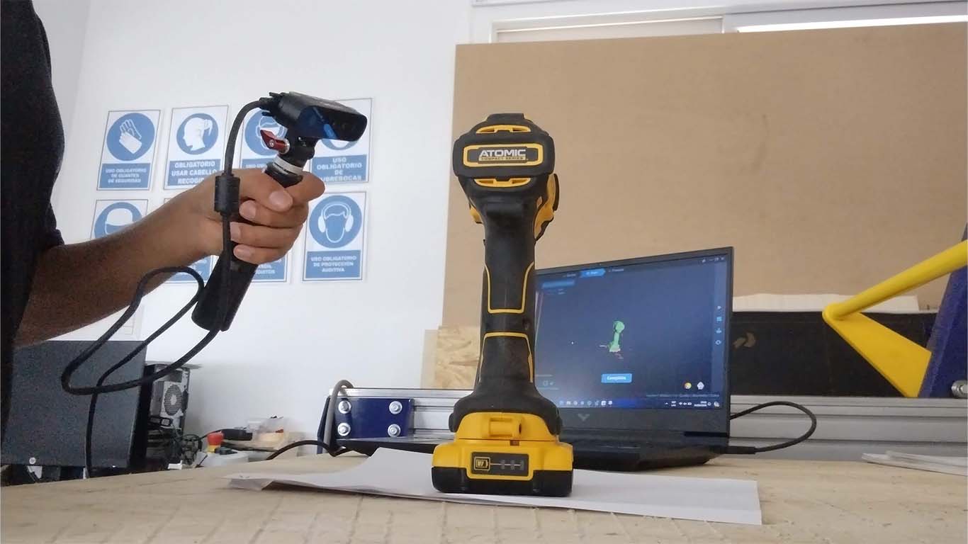
In week 9 of the FAB ACADEMY, the 3D SCANNER CREALITY arrived at the fab lab. First time I saw this type of machine and I found it super interesting how the scanners work and to update my week of 3D SCANNING AND PRINTING I am going to show how I made a 3D scan of a cordless drill. I found the way of doing it and the results in the end very interesting.
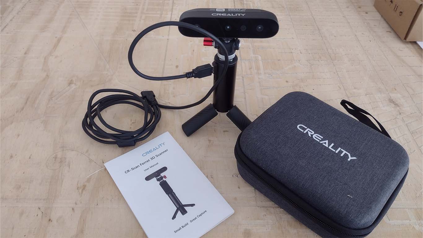
First, we need to download the 3D SCANNER program from their website, which we can find on the supplier's website and the characteristic that the scanner has is that it can be used for both PC or laptop and cell phones, in my case as I already scanned with my cell phone, I'll connect it to my laptop.
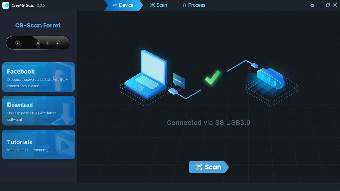
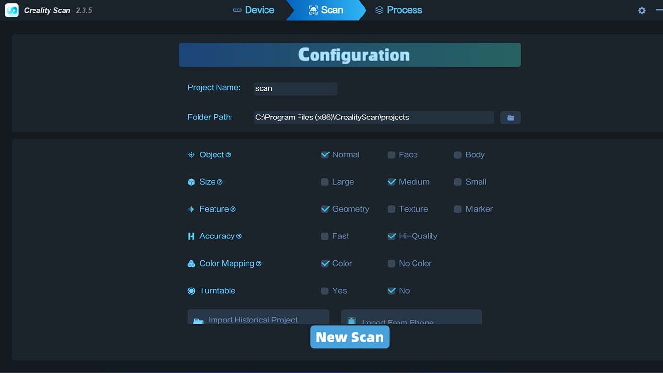
After the program reads the scanner, it will ask us for some settings that we would like to give it to start a new scan of an object.
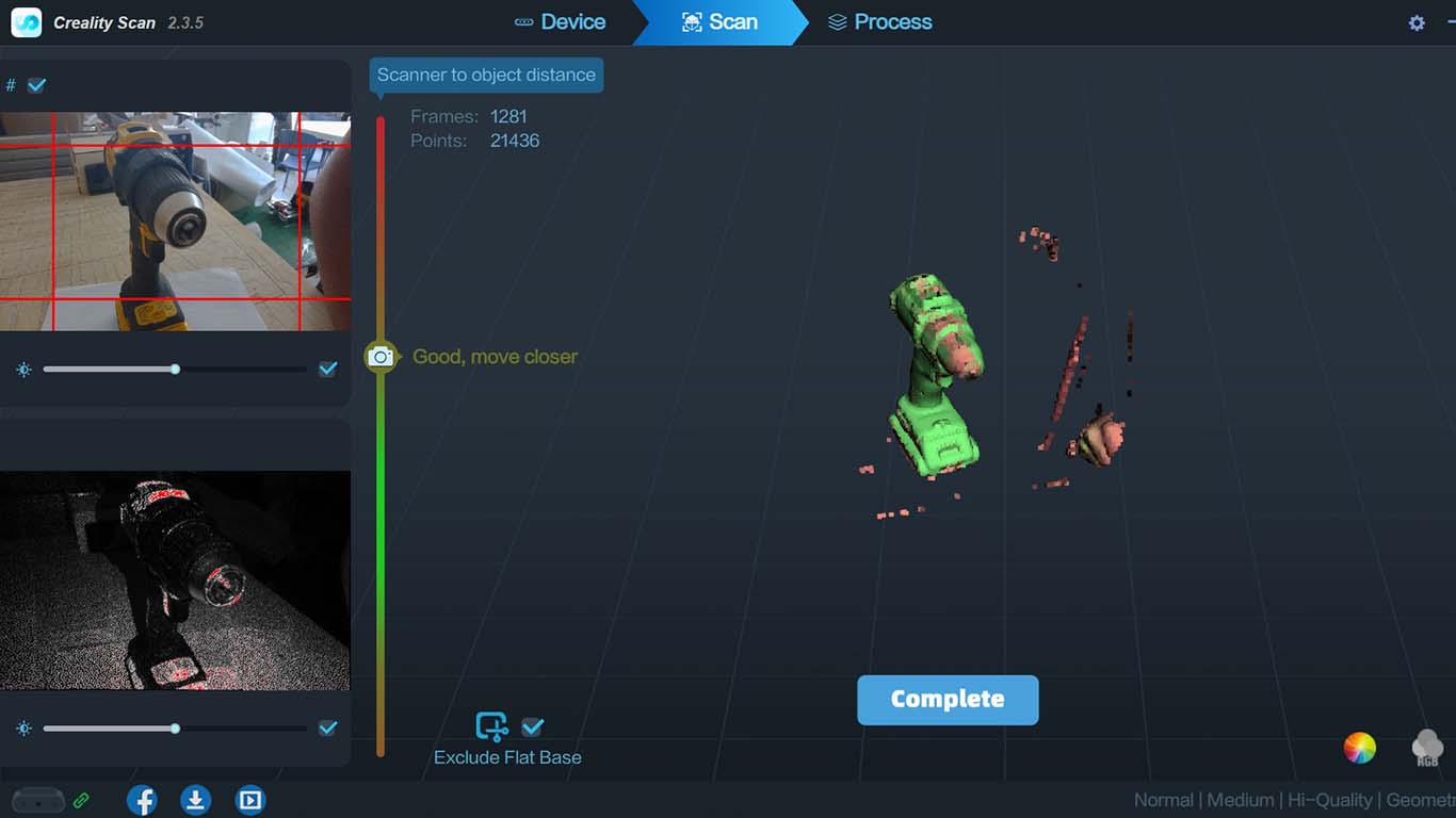
Finally, we will enter the scanning area where the work window, the cameras and the progress of the object scan are shown.
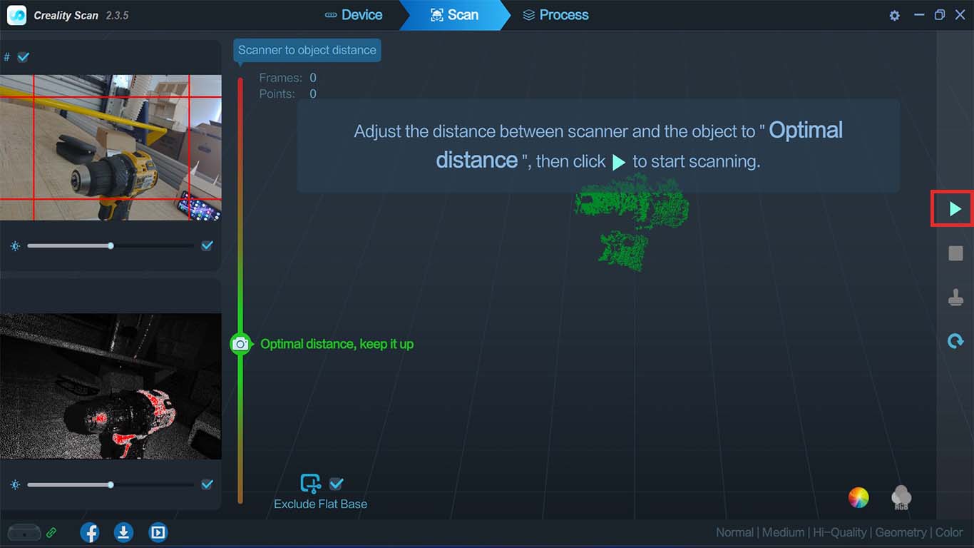
Here are some photographs when I started using the 3D scanner, I had to be careful and check the screen to prevent the program from having gaps since it warned me when the sequence was lost, I had to do it slowly and from a maximum distance of 20 cm now. If it was too close or too far, the program warned me and I had to find the last scan point again.
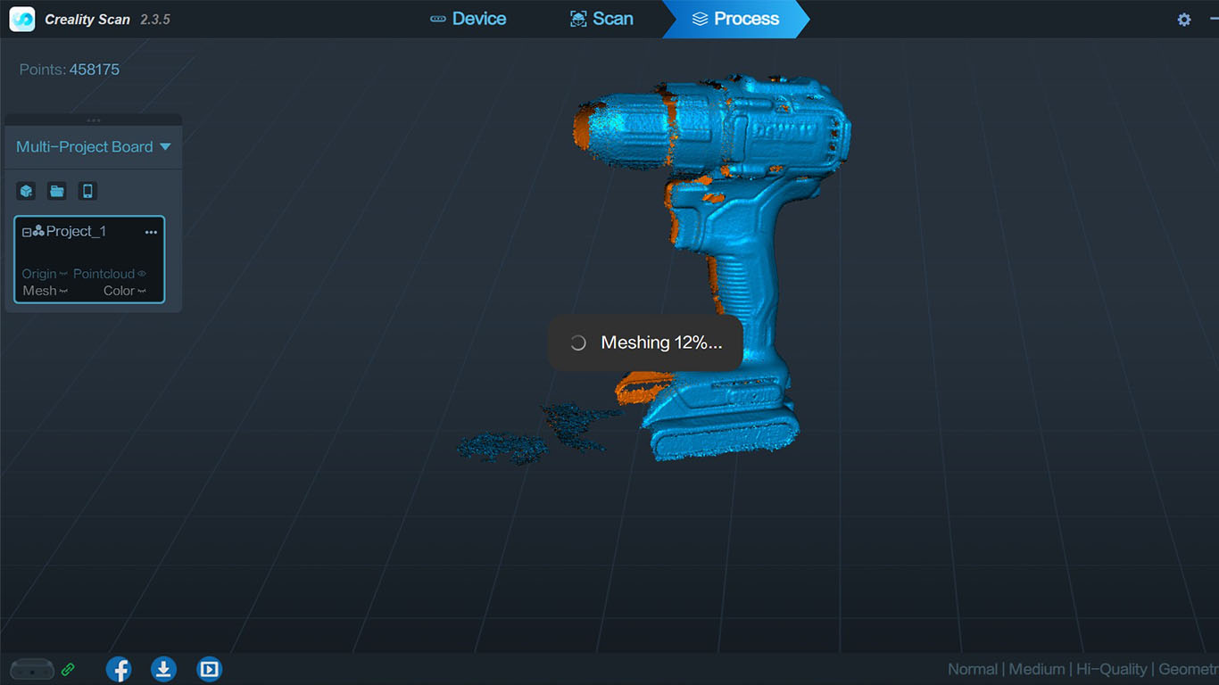
After doing a correct scan of the cordless drill, it took me twice to scan the entire object. The program goes through a phase of OPTIMIZATION and MESHING of the scanned model until it shows me the object with the real colors on my laptop screen.
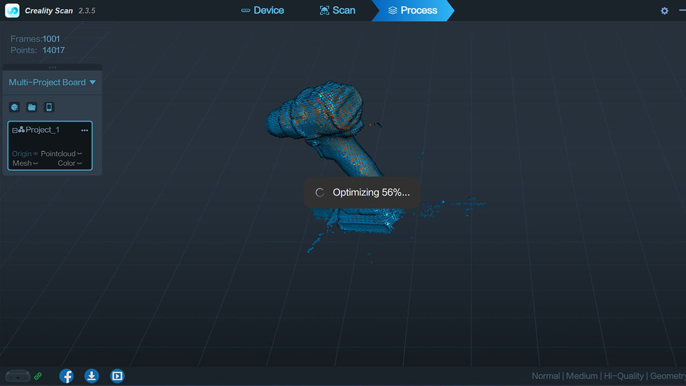
Here the scanned model goes through the MESHING phase which takes approximately 2 minutes.
Finally, after the program performs both processes, it gives us a preview of our scanned object on the screen, where we can rotate it and see the details it was able to scan.
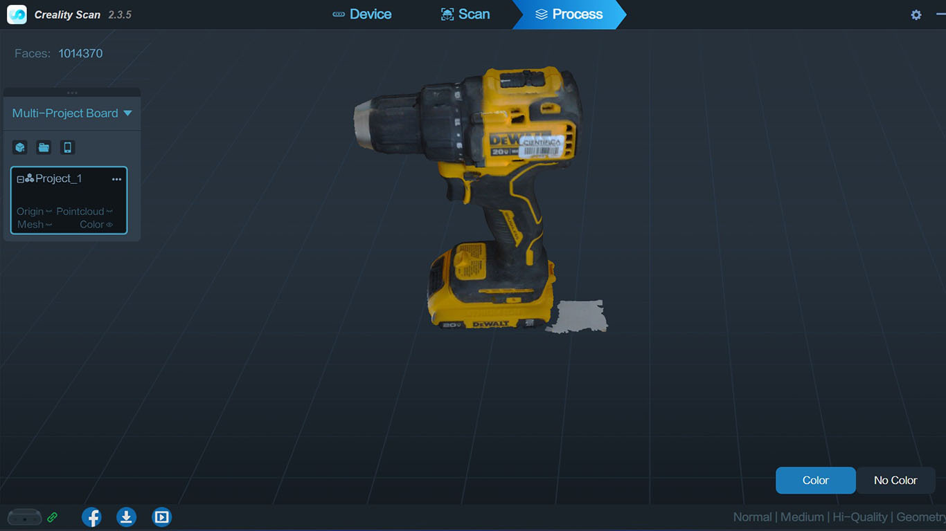
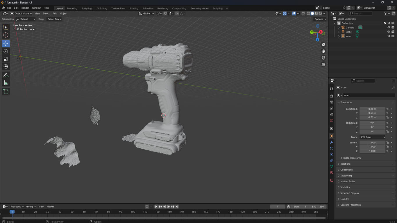
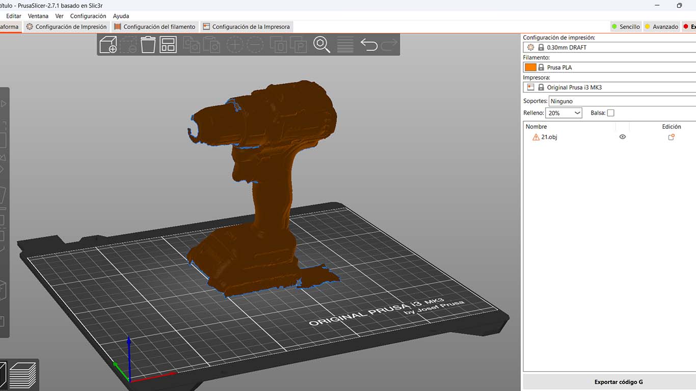
After obtaining the preview of the model in the program, we can export it in OBJ format. where from there we can work in any 3D program. In my case I will export it to Blender to see what the model looks like and from there I will go to Prusa Slicer to see if 3D printing is possible.
FILES
Here you can download all the files that I have made for the following assignment: