This week's assignment was:
- Do your lab's safety training
- Test runout, alignment, fixturing, speeds, feeds, materials, and toolpaths for your machine
- Make (design+mill+assemble) something big (~meter-scale)
- Extra credit: don't use fasteners or glue
- Extra credit: include curved surfaces
ORGANIZATION
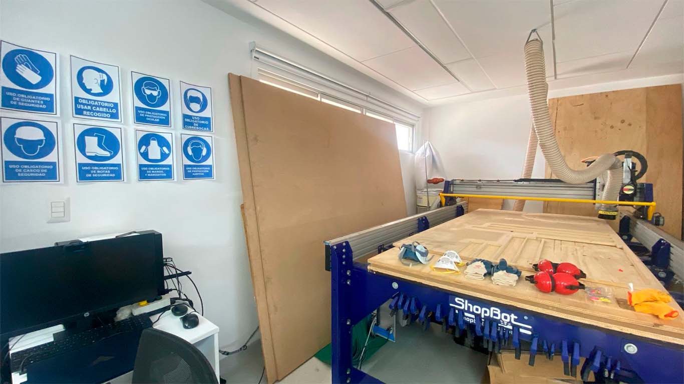
At the FAB LAB UCSUR we review all the safety protocols for the use of the CNC machine and use of protective equipment for the group and here I also show how I organized myself for this week.
| Wednesday 6th: | Fab Academy classes, organization for the week and preparing the materials and review the FAB LAB security protocols. |
|---|---|
| Thursday 7th: | Talks about safety and health at the FAB LAB, meetings with instructors for recommendations and design progress for the assignment. |
| Friday 8th: | Purchase of plywood sheets to cut on the CNC. Carrying out tests for the material and design. Design mockup cutting |
| Saturday 9th: | Enter OPEN GLOBAL TIME, cutting something big on the CNC and assembling the design. |
| Sunday: 10th: | Documentation and commit of everything done until Saturday. |
| Monday 11th: | Taking design photographs and making 2nd commit. |
| Tuesday 12th: | Review the documentation and make the last commit for the following week. |
GROUP ASSIGNMENT
Here I leave the link to go to the group assignments page.
Clic here to visit the WEEK 7 GROUP ASSIGNMENT PAGE
DO YOUR LAB'S SAFETY TRAINING
TRAINING
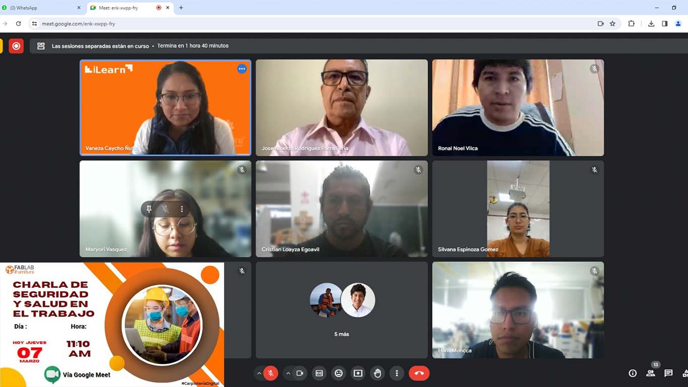
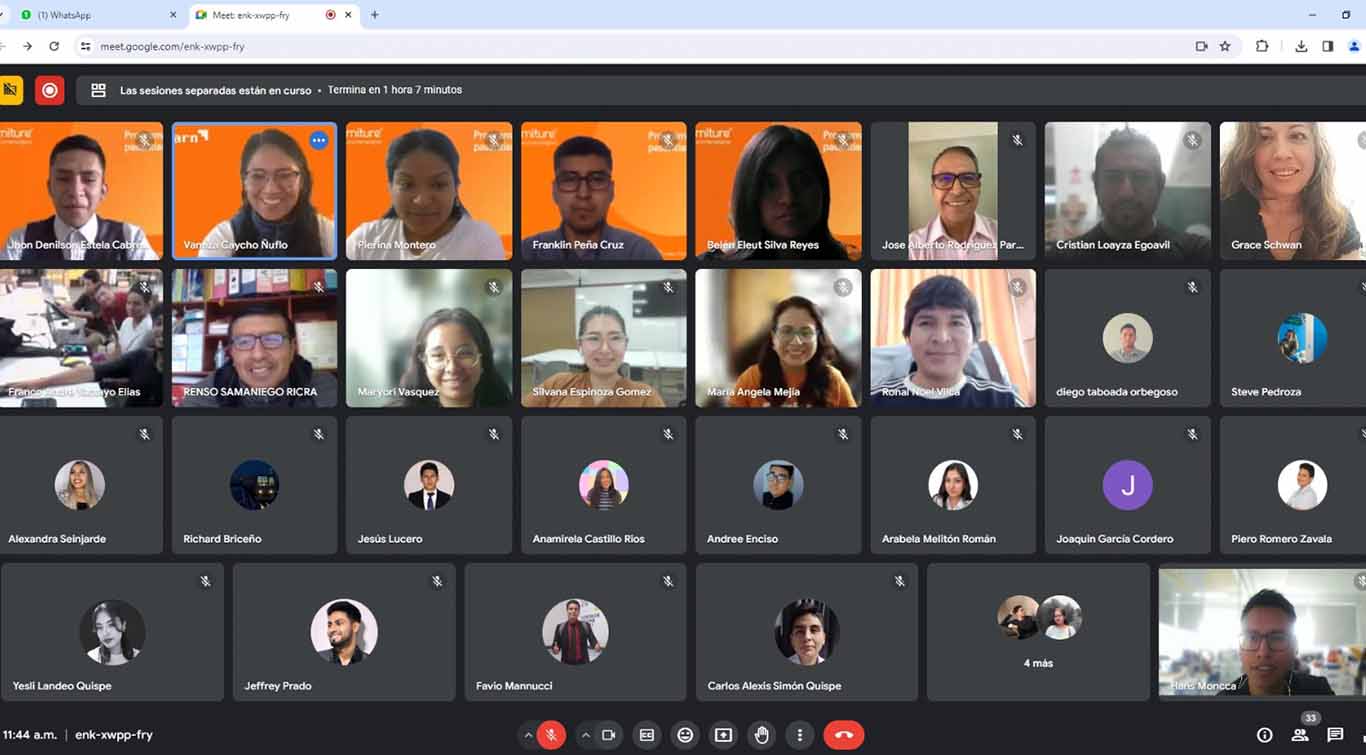
On Thursday 03/07, teacher Vaneza organized a virtual training for us from engineers to explain to us about SAFETY AND HEALTH AT WORK , especially dedicated to FAB LABS. Here we were able to receive a prior talk to learn about all the characteristics that we have to take into account to be able to work safely and avoid accidents.
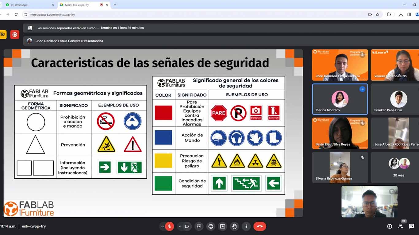
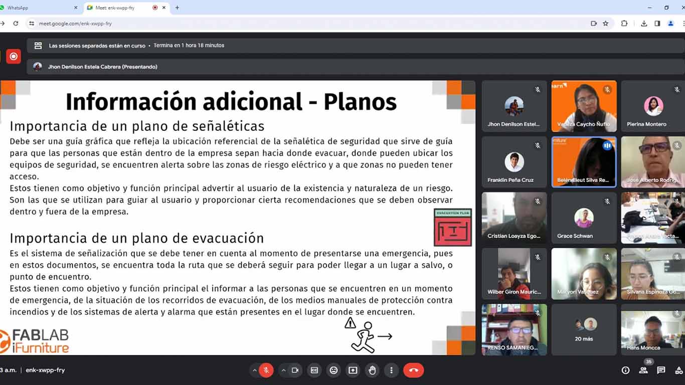
The security specialists first explained to us the signs that our laboratory must have and everything that each of them must contain. Signage in these spaces is important to avoid accidents and be safe when using machines.
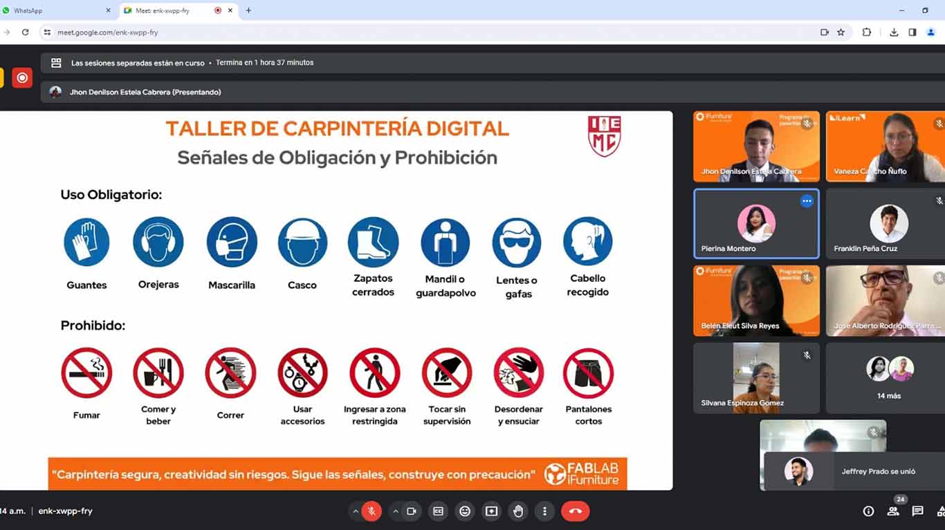
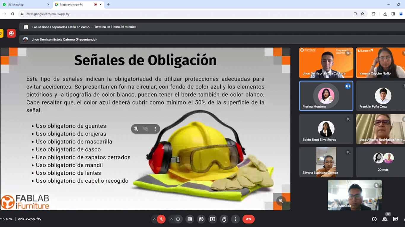
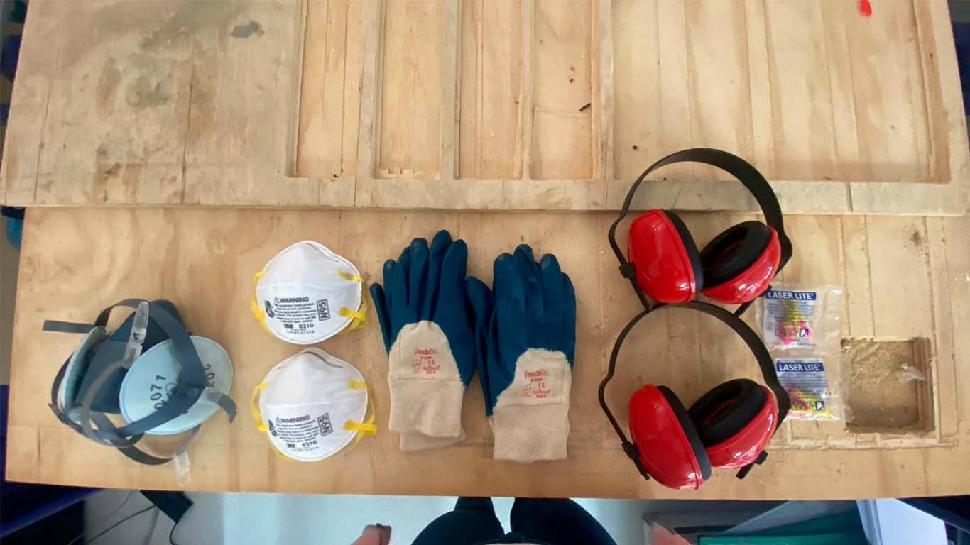
Then they explained to us about the use of "EPP" safety equipment, where we must comply with 8 important aspects to be able to work in the laboratory. Let us remember that each of them is very important for our safety and health.
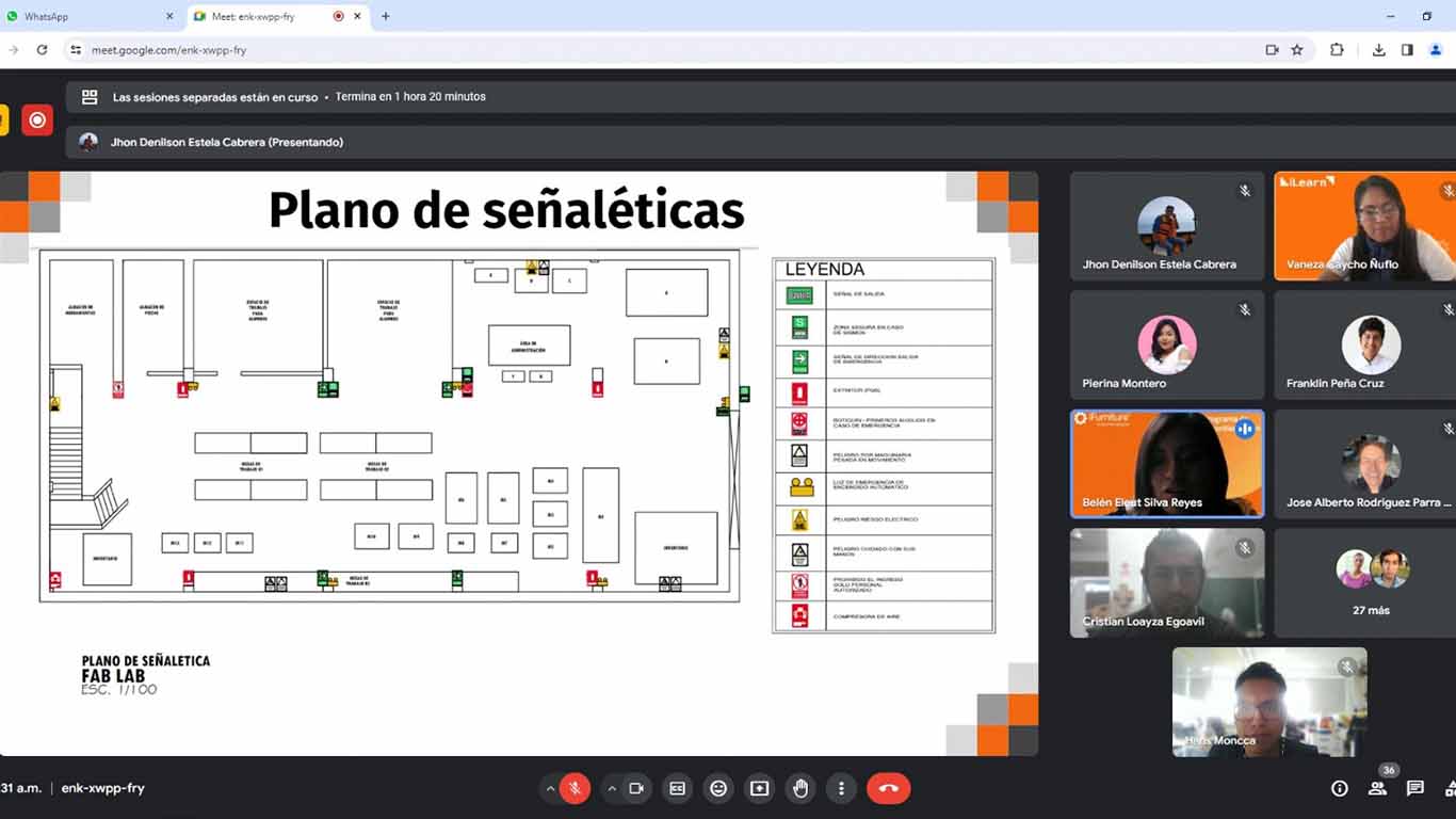
Finally, it is also important to know the laboratory, which is why they explained to us that we must have our map to know the location of each machine, safe areas and the location of fire extinguishers. The plan is fundamental for our safety and must comply with aspects that must be taken into account in our laboratories.
Here I show a screenshot at the end of the talk that was very interesting and that also made me reflect on some things that were not being taken into account in the laboratory of the Scientific University of the South.
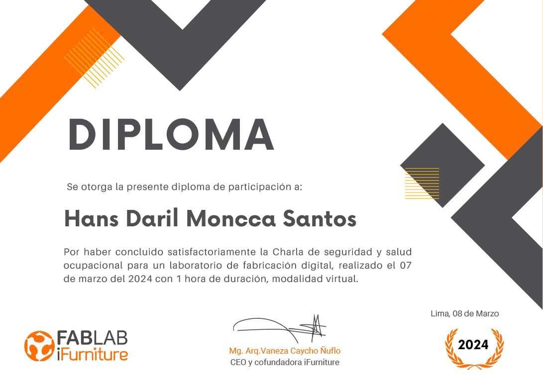
Here I leave a screenshot of my certificate awarded by Ifurniture for health and safety training. Thank you teacher Vaneza.
DOING MY LAB SAFETY
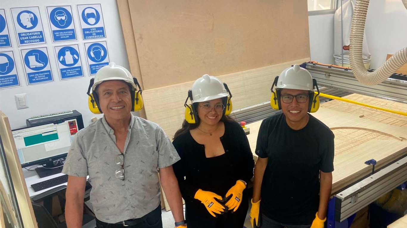
After the safety talk, my friend Maryori and I began to supervise all the aspects that we must consider in the FAB LAB. So we got our safety equipment ready and we also checked if we had all the signs, but to do it and be able to comply with the safety aspects and be able to start working.
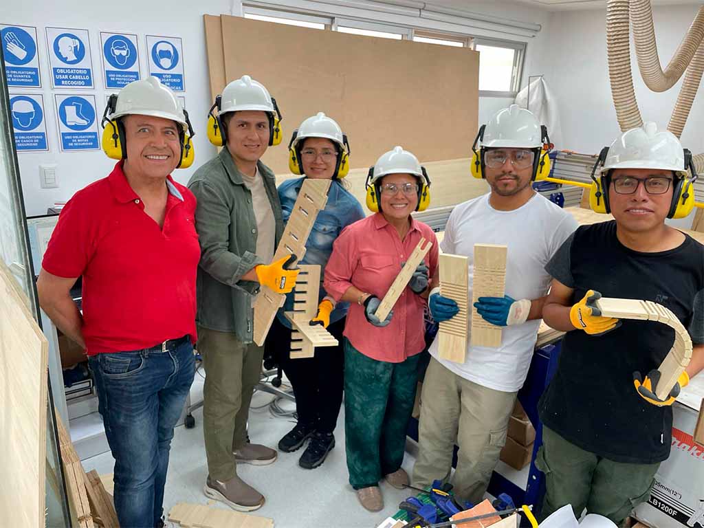
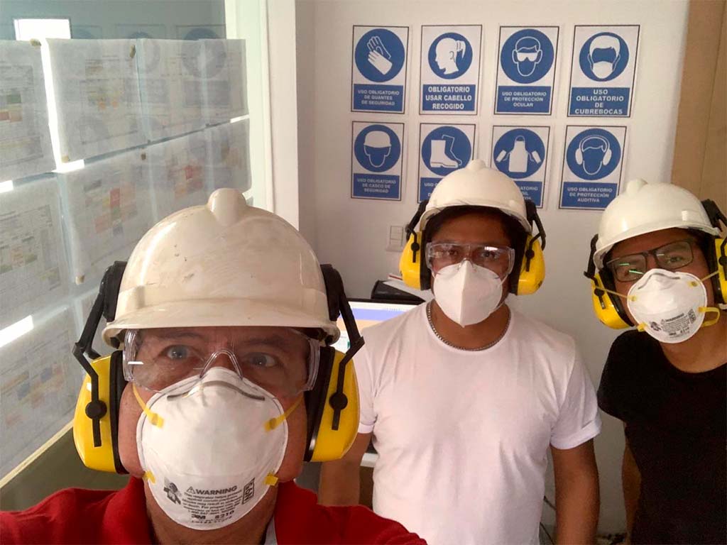
The following photographs were taken on Saturday 03/09 where we met at the FAB LAB Cientifica del Sur to carry out our group work and also to advance with our individual work. We all committed to working safely.
FEATURES, CONFIGURATION AND IMPLEMENTS OF THE CNC MILLING MACHINE
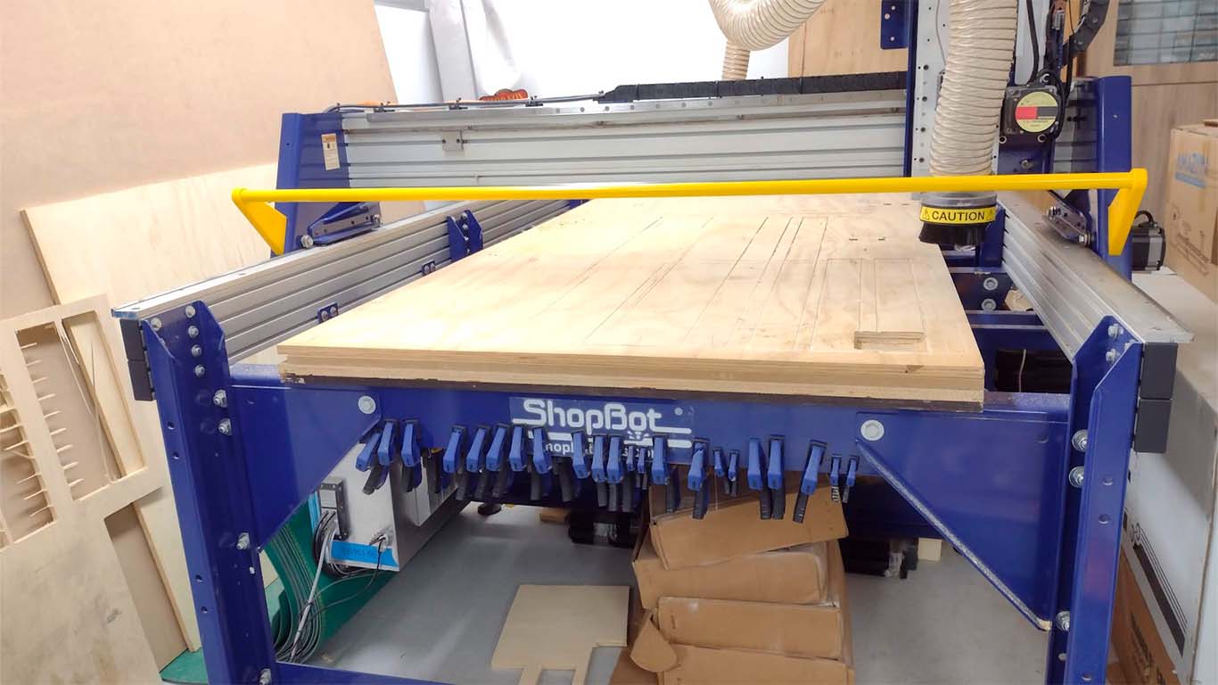
SHOPBOT PR-ALPHA
The CNC router machine that we have at the Universidad Cientifica del Sur is the SHOPBOT PR ALPHA MODEL 96 - 48, which has the following technical specifications:
| CUT / MOVEMENT AREA: | 105” x 61” x 8” |
|---|---|
| XY POSITIONING SPEED: | Variable, max. 1800”/min. |
| Z POSITIONING SPEED: | Variable, max. 900”/min. |
| LINEAR CUTTING FORCE: | Approximately 150 lbs. |
| INPUT VOLTAGE: | 220v single-phase, 230v 3-phase and 380/460V 3-phase power options are available, depending on tool and configuration. |
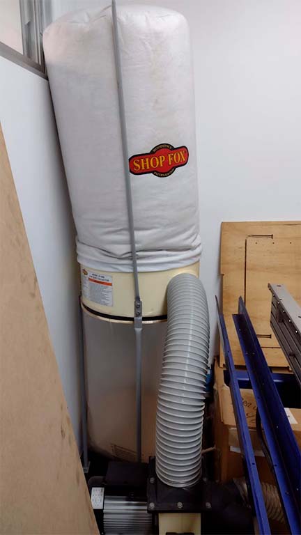
SHOPFOX - DUST COLLECTOR
The shopbot also has its dust collector that is located on one side of the laboratory, here I leave its technical specifications and its use is important when cutting.
| AIR SUCTION CAPACITY: | 1.550 CFM/td> |
|---|---|
| STATIC PRESSURE: | 12,3 inches |
| STANDARD BAG FILTRATION | 2.5 microns |
| MOTOR AMPLIFIER POWER: | 220-Volt - 12A |
| BAG VOLUME: | 5.4 cubic feet |
A REMINDER...
On the afternoon of Friday 03/07, teacher Vaneza gave us a small class on CNC Router and all the aspects that must be taken into account. The truth is that she gave us a lot of information to learn about the mills and all their characteristics.
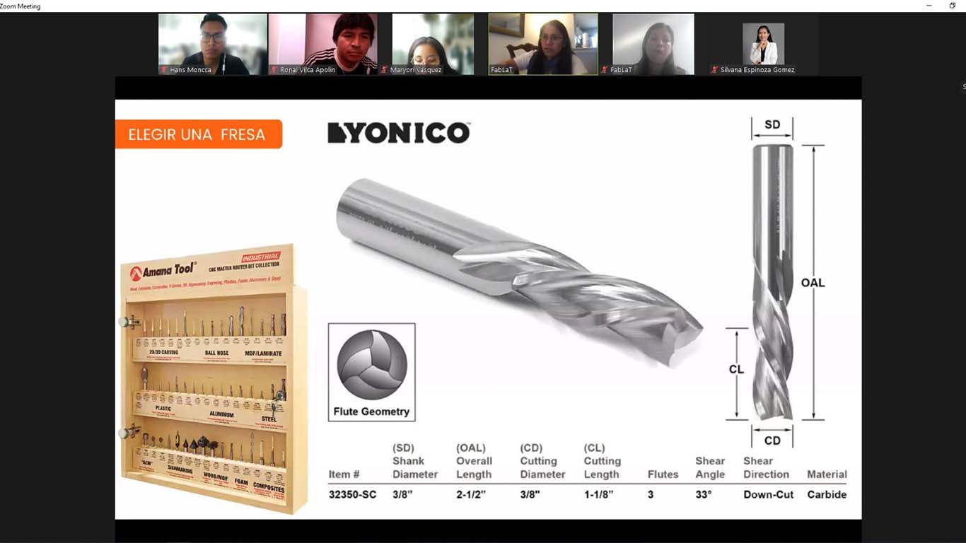
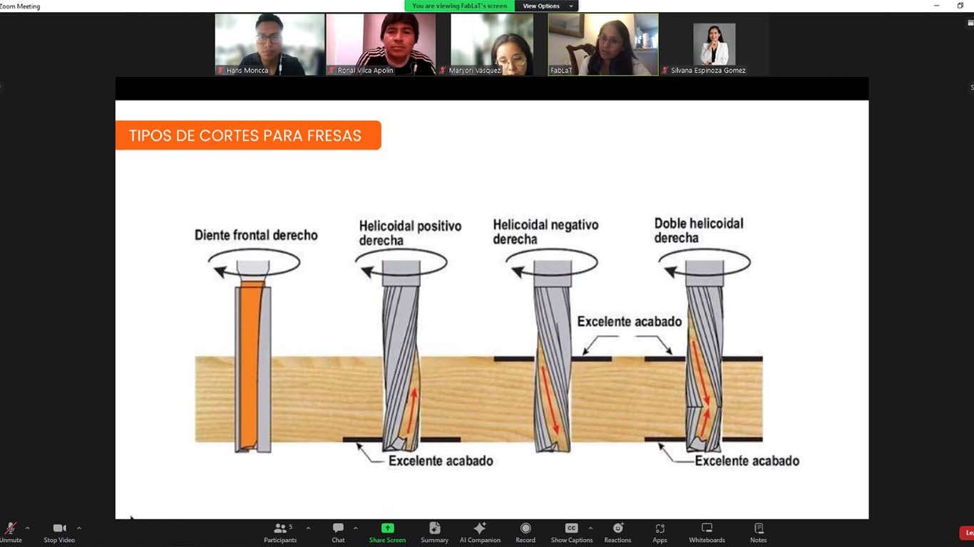
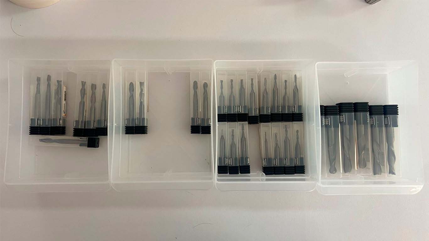
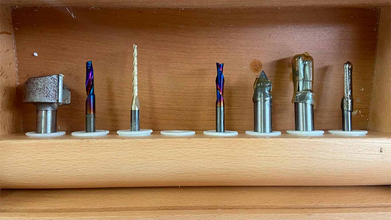
FAB LAB UCSUR IMPLEMENTS
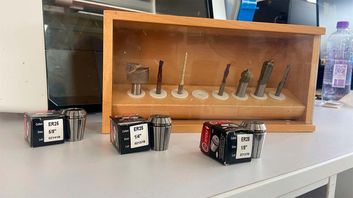
At the FAB LAB UCSUR we have the following implements for the CNC router machine. 1/4", 1/8" and 5/8" cutters together with their ER25 collets and a cutter that comes with the SHOPBOT. For our group and individual work we will use the 1/4" cutters, together with their appropriate collet since we have many more spare parts in case we have some problems and we can do the work.
VCARVE PRO - CAM
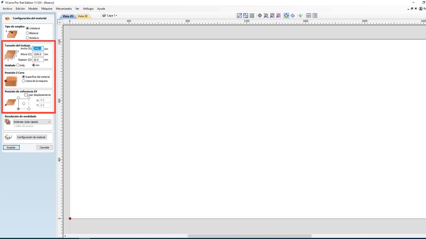
At the FAB LAB UCSUR we have the VCARVE PRO program that we use to use the CNC router and the following steps will be carried out with all the tests and with any document that we want to send to be cut. First we open VCARVE PRO and configure our material. In this case we have a 2440 x 1220 mm x 15 mm plywood . But to achieve a better cut of the pieces, we will increase + 1 mm, that is, 16 mm and be able to achieve the exact piece.
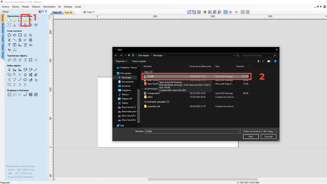
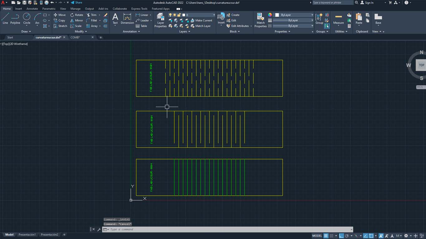
Then we import the file we want to cut, in this case I will do it with a DWG file and we select the file we are going to cut.
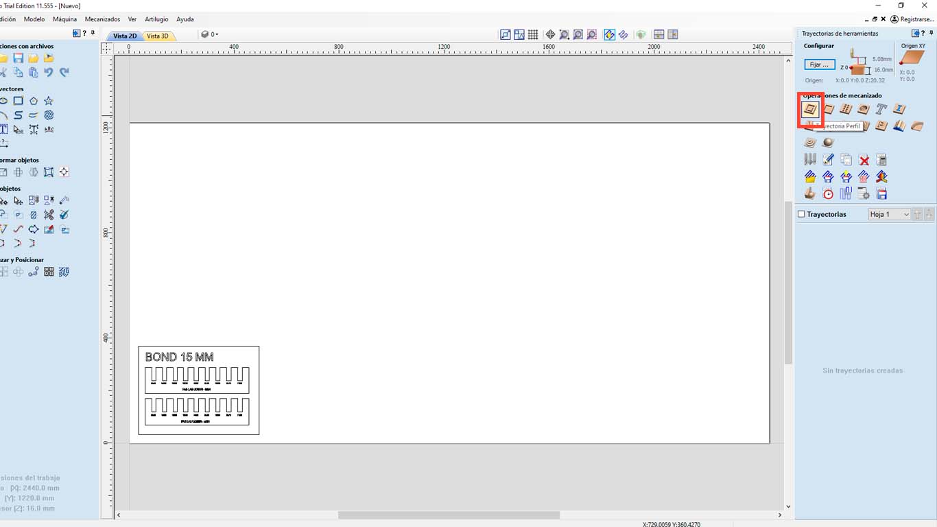
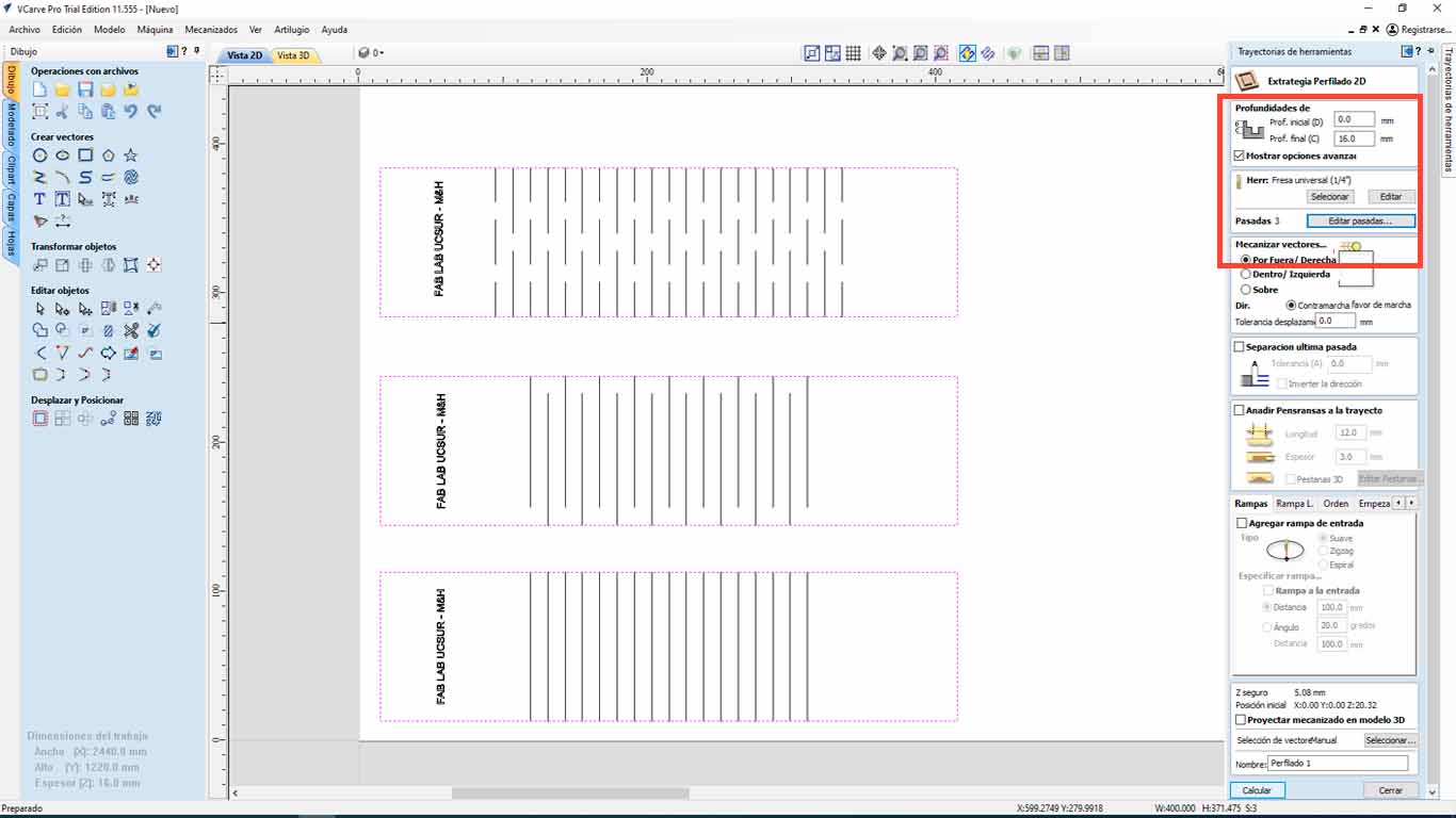
After that, we go to the upper right part of the program and we will find the "TOOL PATHS" button and look for the "PROFILE PATH" option, which is what we will use to cut the material. We have many options to do and that you can explore.
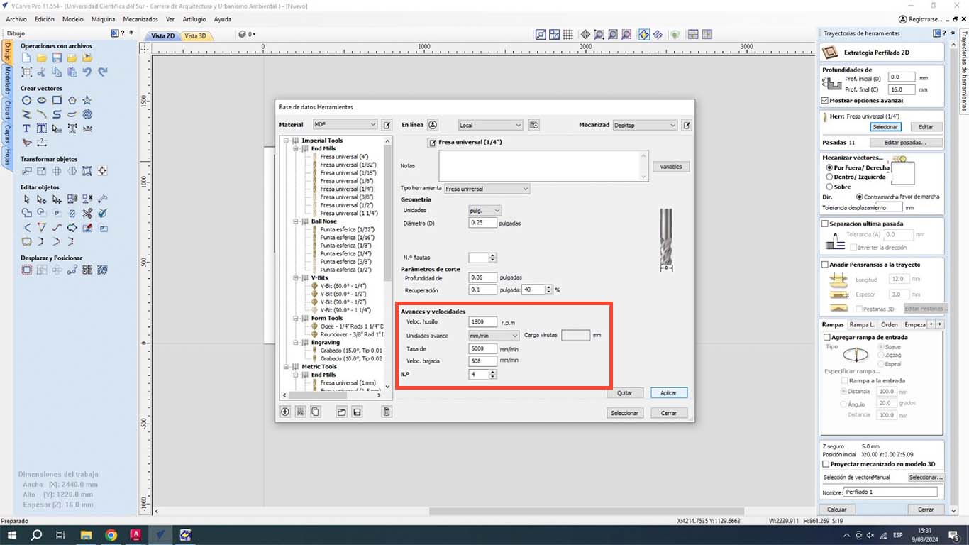
Then, in the 1st red rectangle, we check if the depth meets the entire thickness of the material. Then we check what type of cutter we are going to use and click "SELECT" to access the tool database, where we can change the size and type of cutter. Additionally, this is where we have to give the speed that the SPLINDER will have and the cutting speed. We have to be careful with it, in this case we will leave it as default.
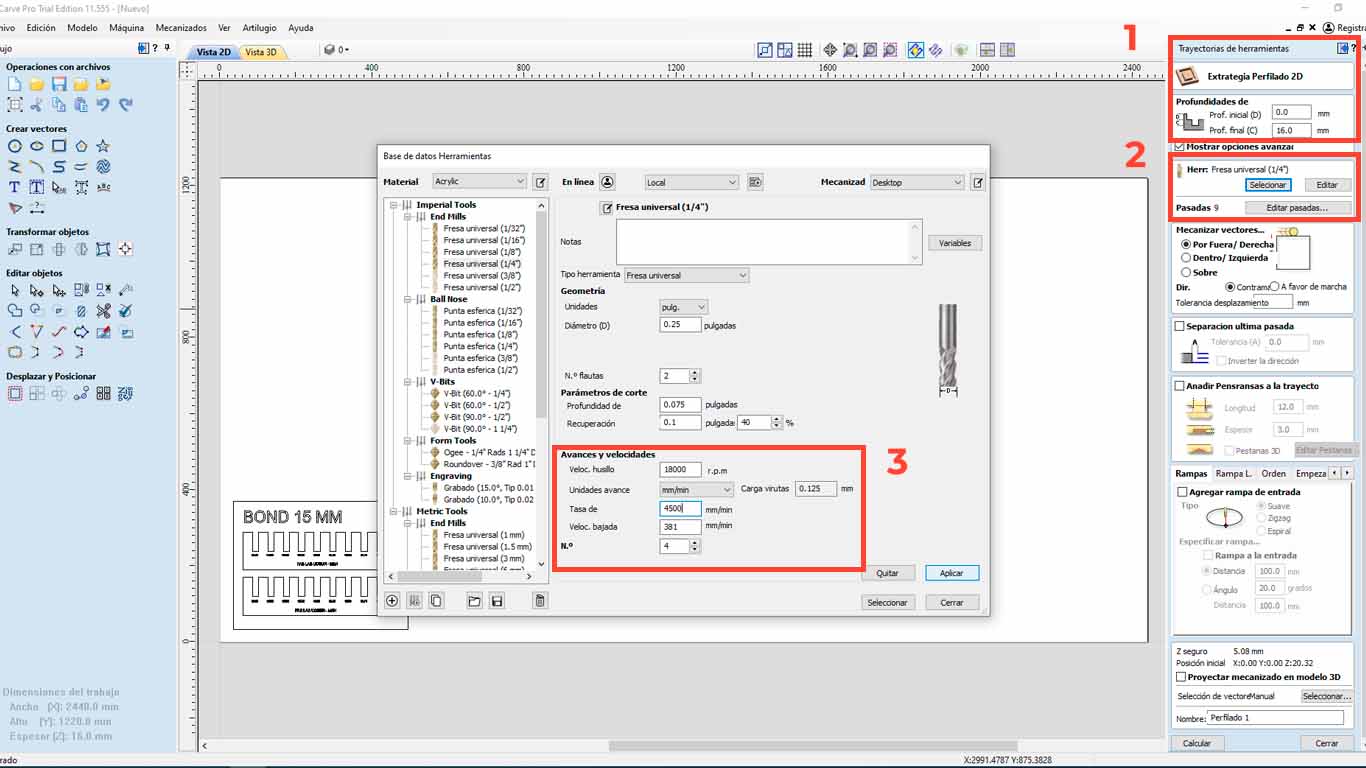
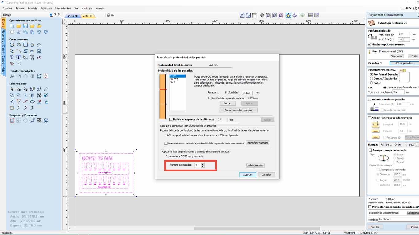
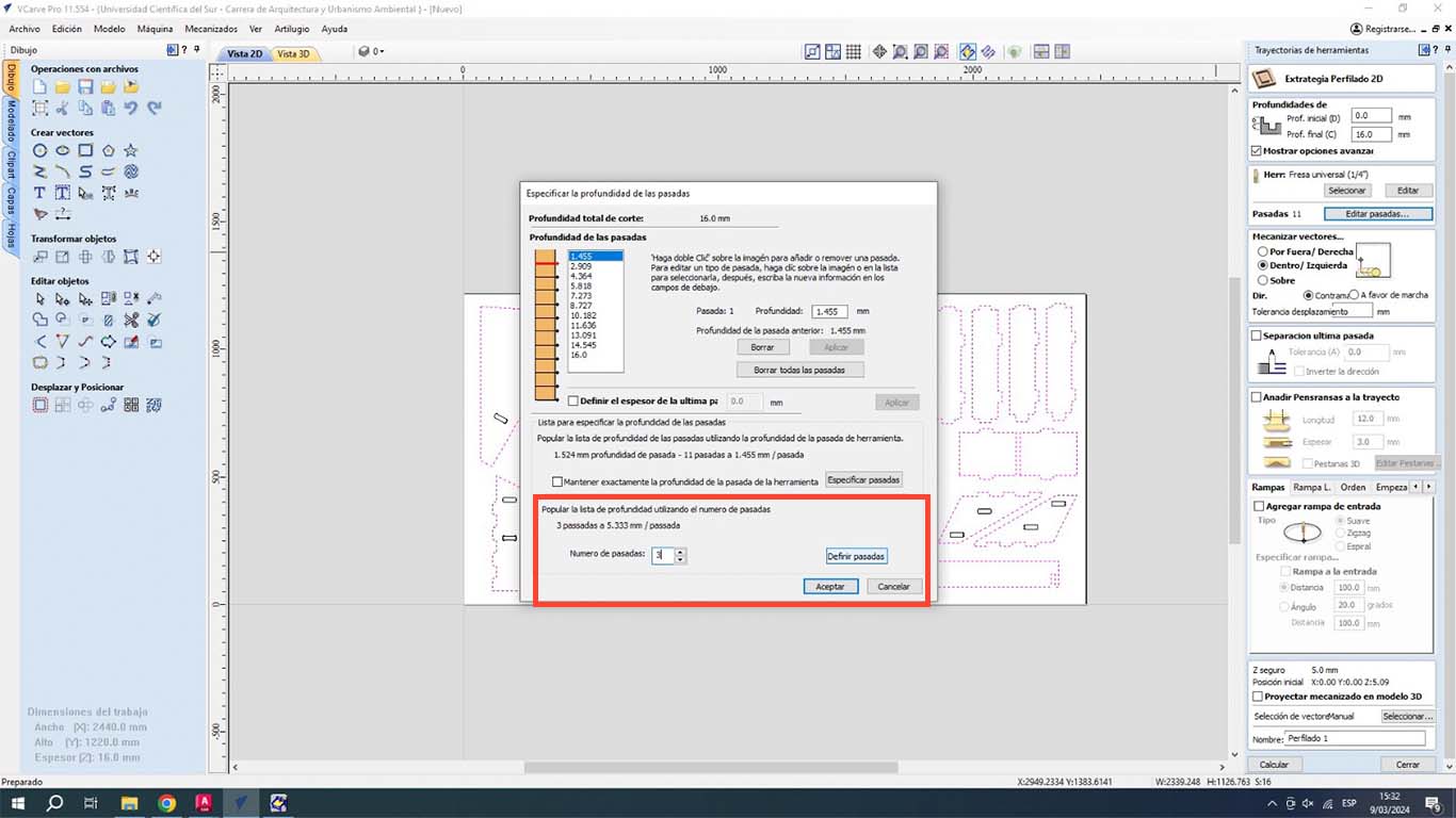
On the other hand, we also have to configure the number of passes that our milling cutter will have on the material. We have to be careful with this and in my case, I will make 3 passes to be able to cut the material.
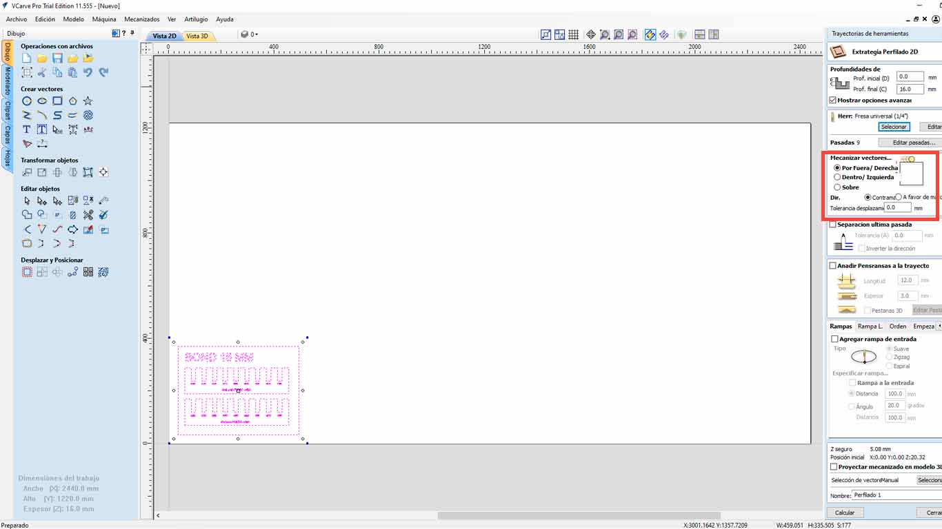
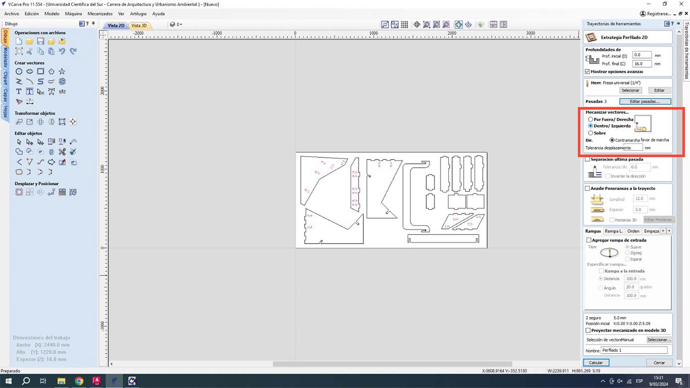
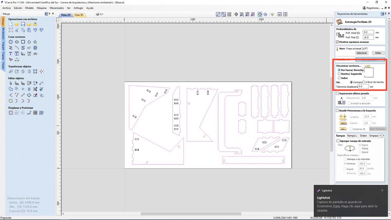
Finally, we have to analyze if we want our cut "OUTSIDE", "INSIDE" or "IN LINE" , this to know what we want. What I discovered is that on the outside it is when it is cutting pieces, on the inside it is used in holes or bones and in Line to make marks like what we are going to use to do the curve tests and accept
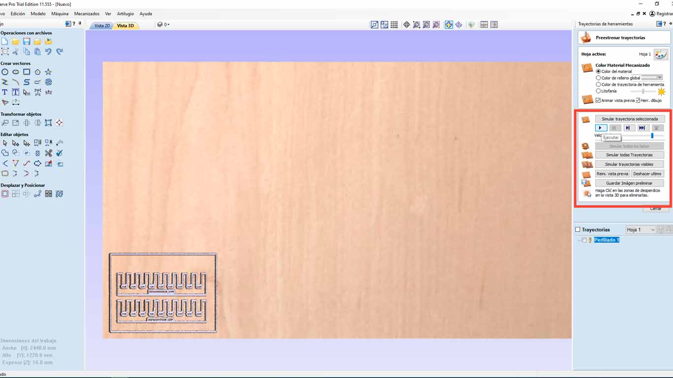
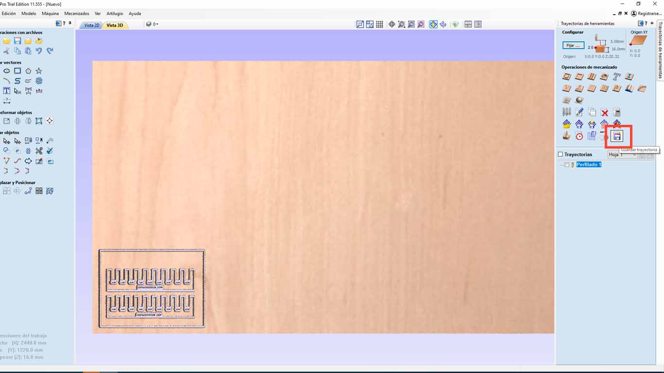
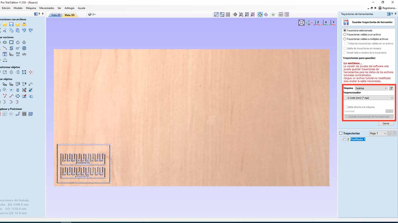
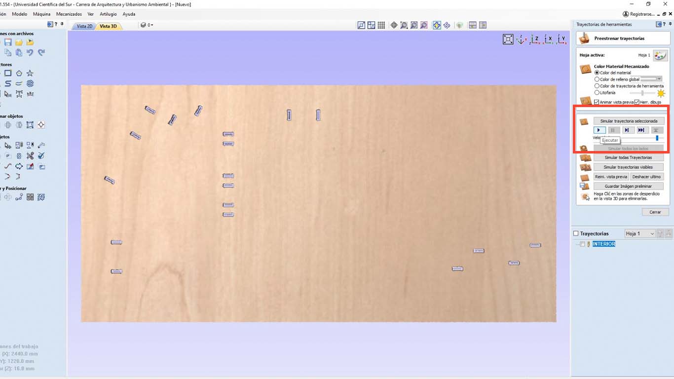
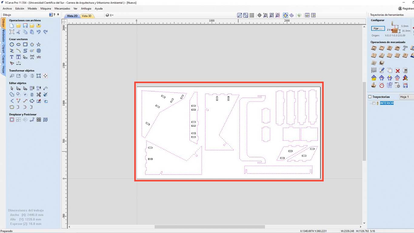
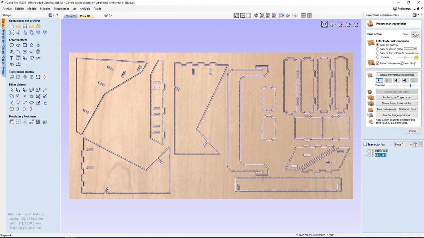
The program will send us to the 3D view, where it will show us a simulation of the cut that the machine will make. Here, we can see if there are any lines that are not being cut or there are some problems. Finally, we save the trajectory and we will go to the machine.
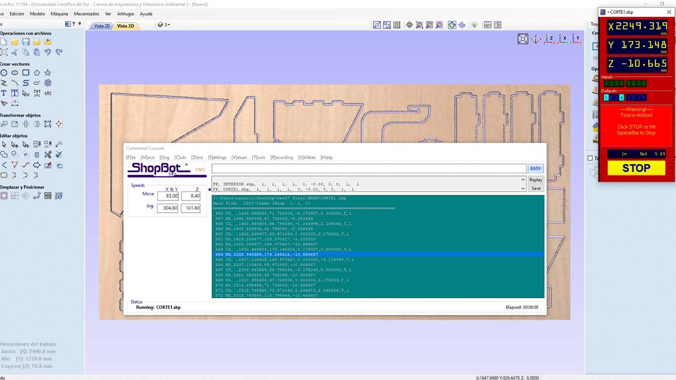
CONFIGURATION THE SHOPBOT PROGRAM
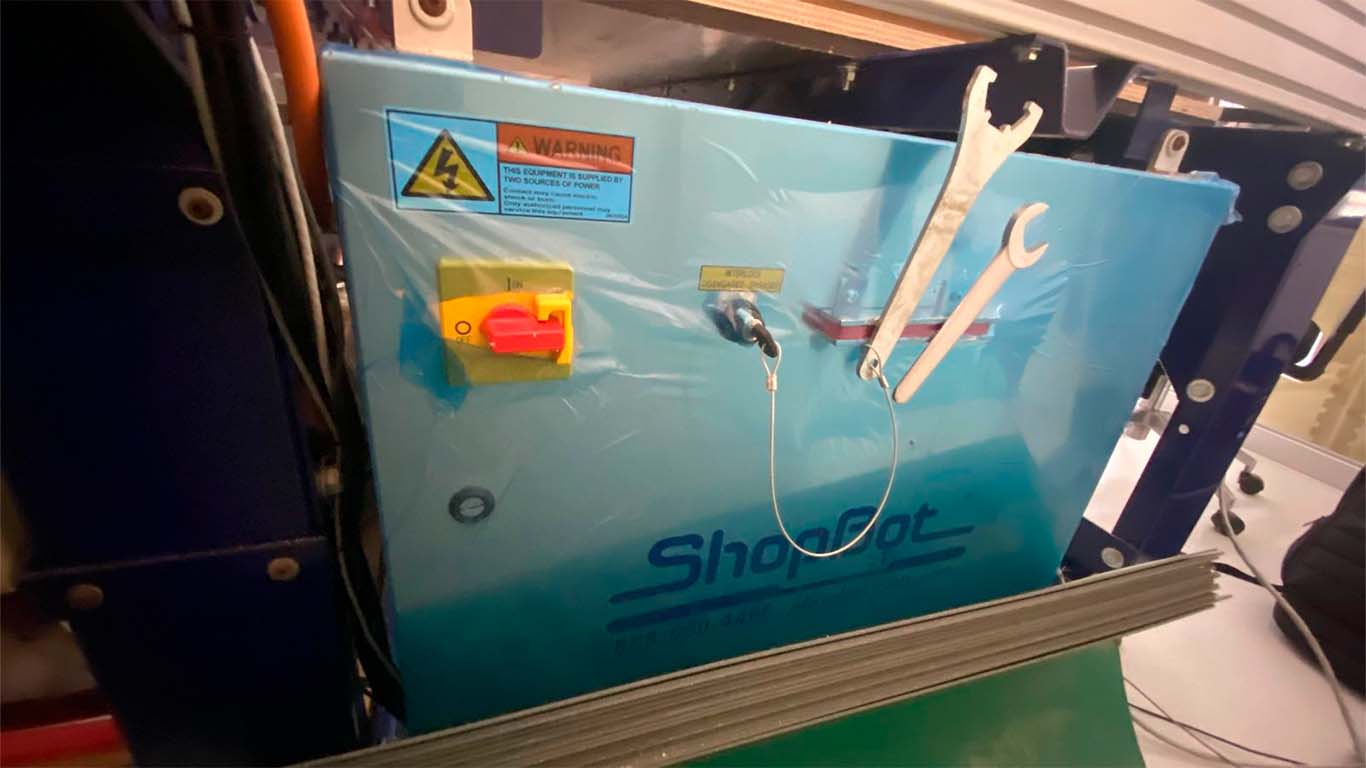
It is important to locate the safety and power box of the SHOPBOT since this is where we will turn on the machine and also activate the SPLINE. Remember to turn it off when changing the mill cutter or spring collet.
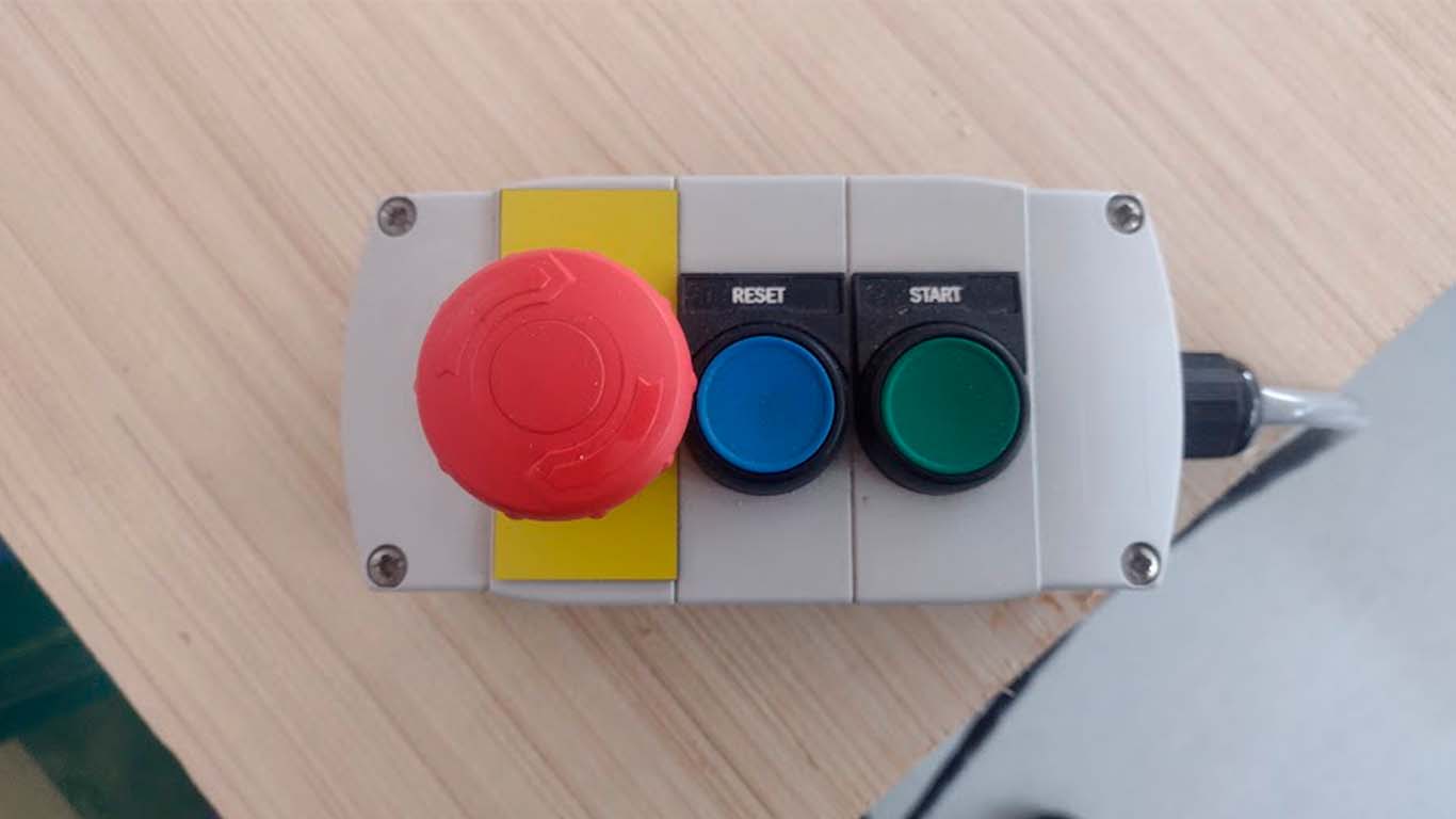
We have to remember that the SHOPBOT presents this control to be able to control the SPLINE at the time we want to activate it and presents an emergency button in case of any accident that may occur. We always have to have it in hand every time we use the machine for our safety and that of our colleagues.
To use the SHOPBOT machine we first have to open the program, then we have to calibrate the X, Y and Z axes. In the case of our machine, we have already calibrated the I will show what the calibration of the Z axis is like.
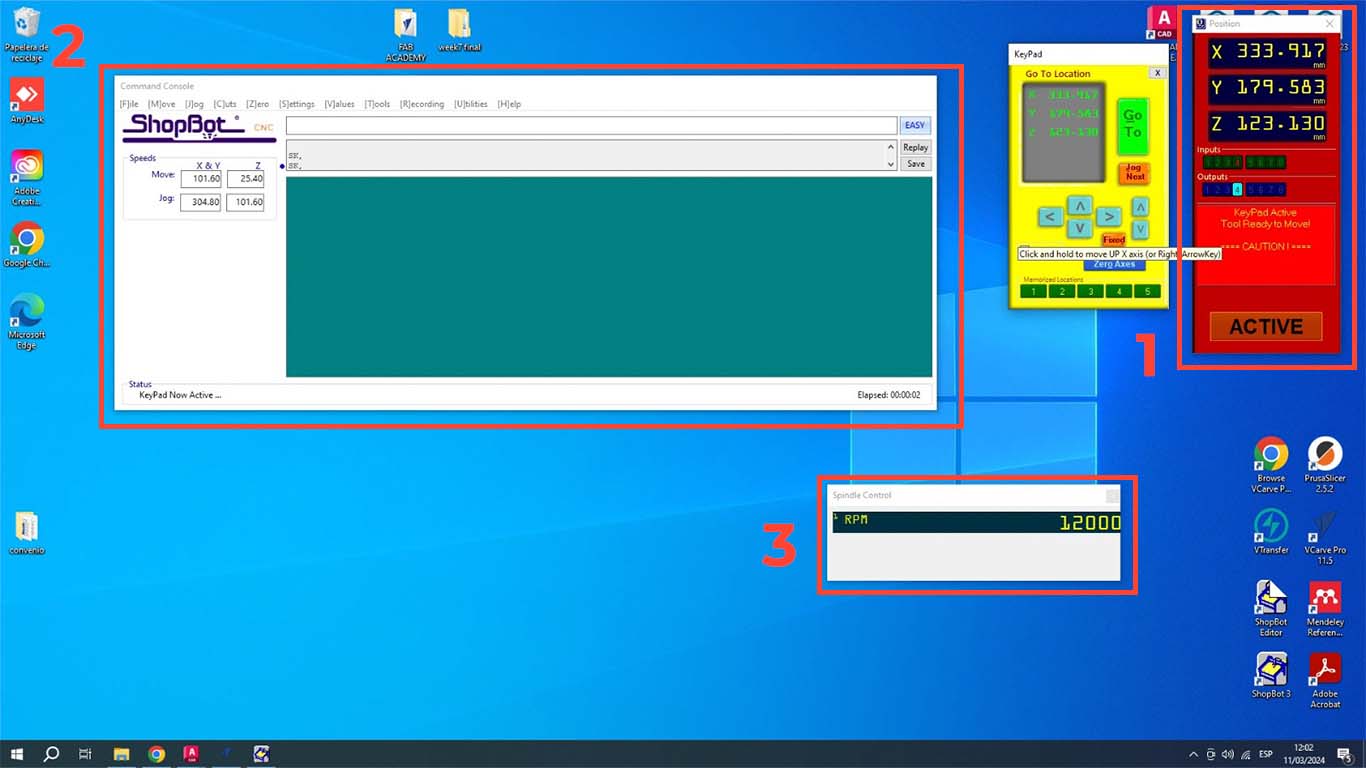
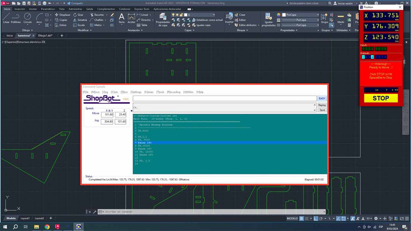
When you open the program, 3 windows will appear. The POSITION is where we perform the calibration, movement and control of starting or stopping the machine. The second window is COMMAND CONSOLE where we can open the trajectories, warm up the machine and, if it is the first time using it, its configuration. Finally, we will have the SPLINDER, which is the speed at which the machine is working and which is important when cutting.
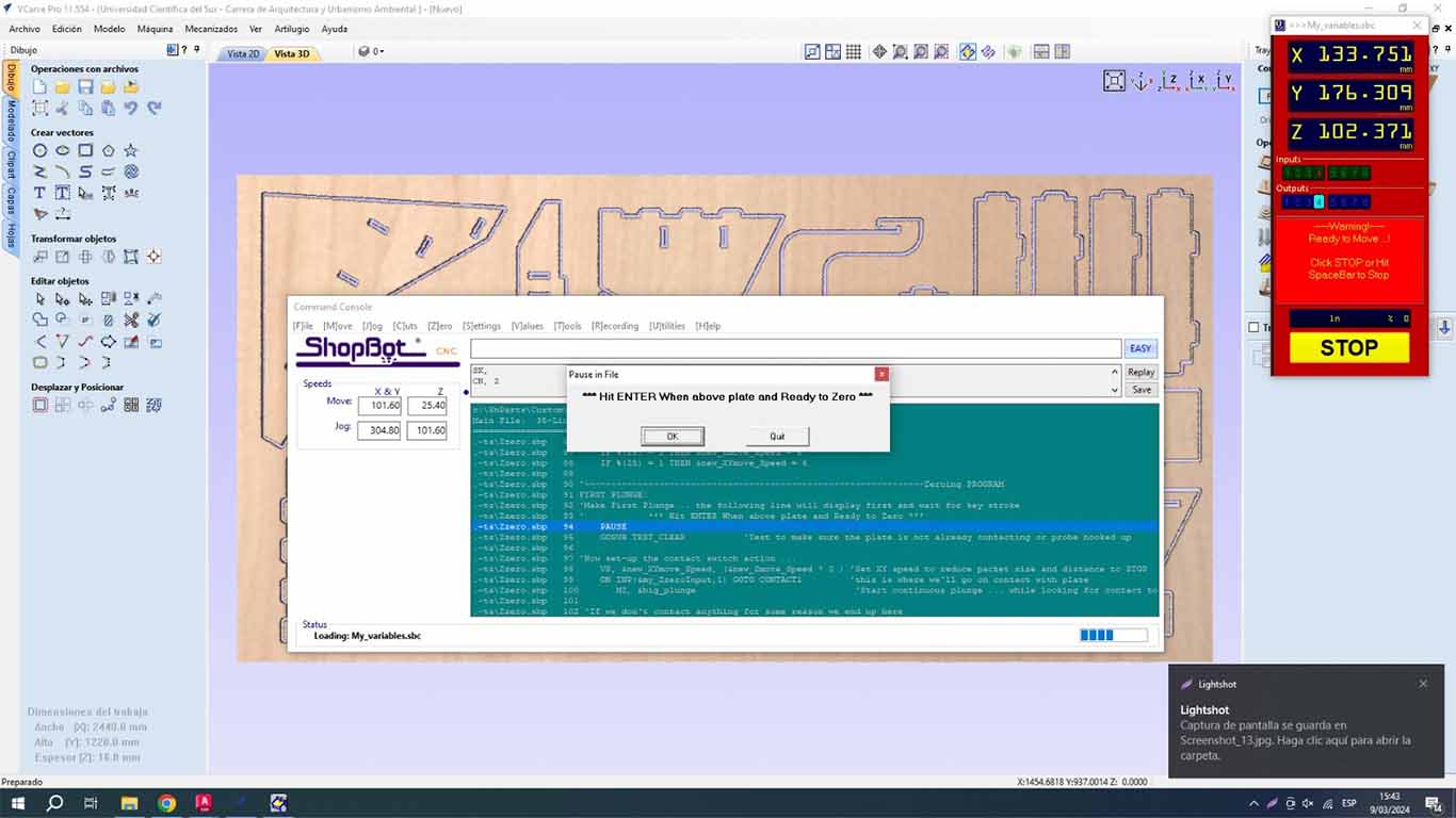
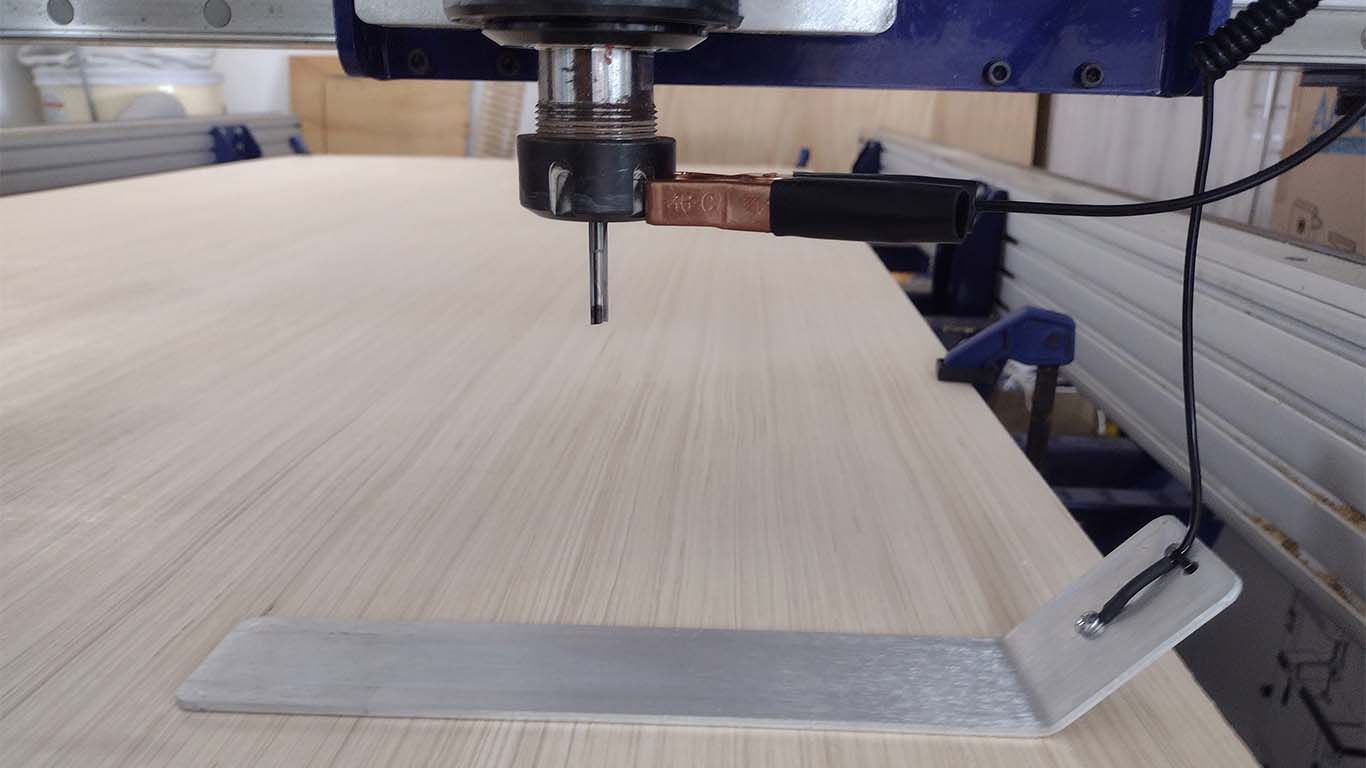
To calibrate the Z axis, we have to click the Z button in the Position window. Before calibrating, we have to place the hook on the SPLINDER and the metal plate on the material, so that the machine can be calibrated as we can see in the photograph and avoid breaking the entire splinder as it can cause this.
From here, the machine will only calibrate its Z axis so that it can start working. Here is a video of how it performs its calibration.
Then we will preheat the SPLINDER , this step is very important when using the machine. The trained personnel told us that it is important to carry out this step to be able to start working with the machine. The recommendation I make is that when we are going to use the machine, we have to follow the following steps and after cutting some pieces, if the machine is stopped for more than 15 minutes, the preheating has to be repeated again, this to extend the useful life of the machine.
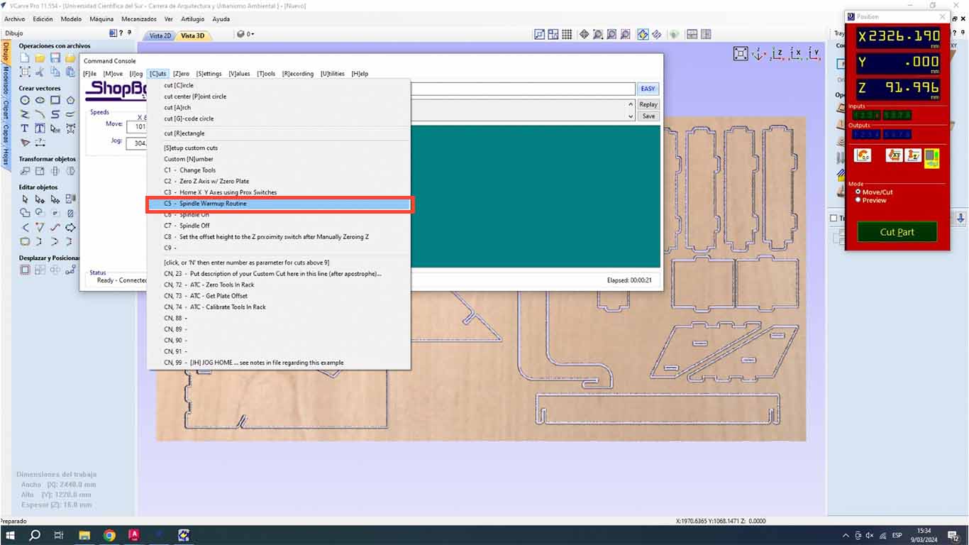
We go to the COMMAND CONSOLE window, we go to the CUTS tab and look for the SPLINDE WARMUP RUTINE button, this is to preheat the machine.
A routine window will appear for the SPLINDER that will change speed until it reaches 12,000 and this routine will warm up the splinder before starting to work. And when you press the START button on the shopbot, the SPLINE will spin until the routine is finished, which lasts approximately 10 minutes.
Here is a video of how the milling cutter and spline start to rotate.
When the SPLINE finishes warming up, we are ready to start working with the machine. We will start with the tests.
TEST RUNOUT, ALIGNMENT, FIXTURING, SPEEDS, FEEDS, MATERIALS AND TOOLPATHS FOR YOUR MACHINE
TEST COMB
The first test we perform is the COMB, which is to find the right fit. For all tests we will use the 15 mm PLYWOOD that will be used in our individual work as well.
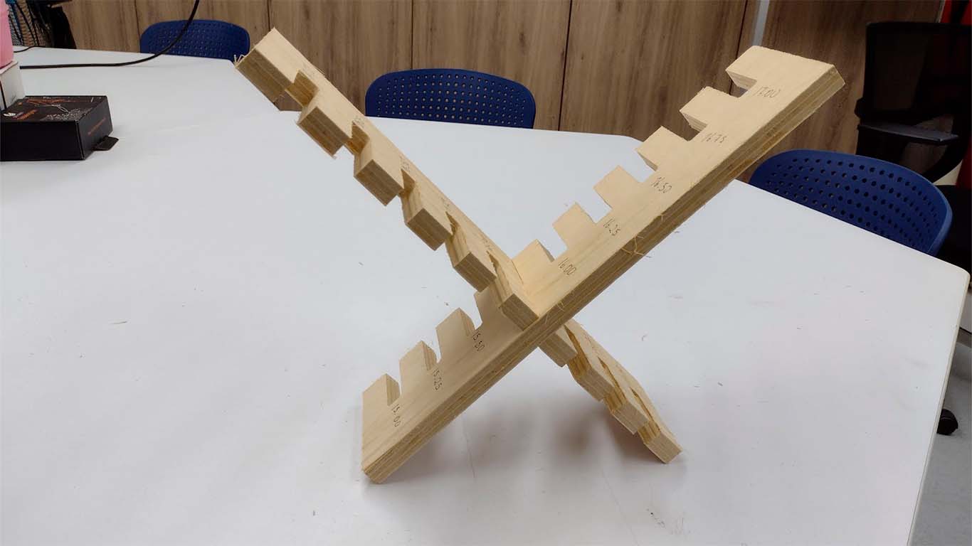
First we thought that the comb was similar to what we did in week 2 with the laser cut and it was not like that. Well, the idea is that the 15 mm plate can fit with another similar piece and instead of enlarging it, we reduce it and it will never fit. Bad calculation, here is a photo of our first comb.
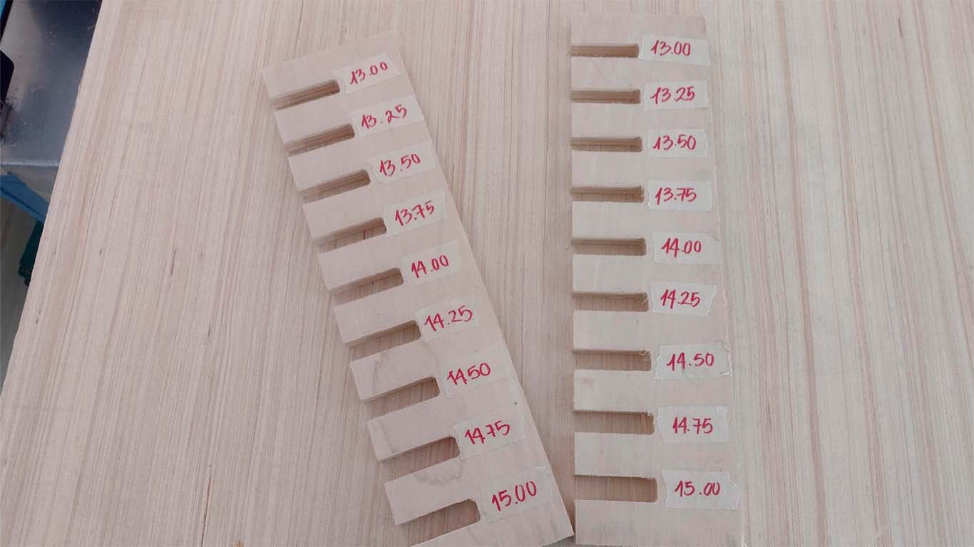
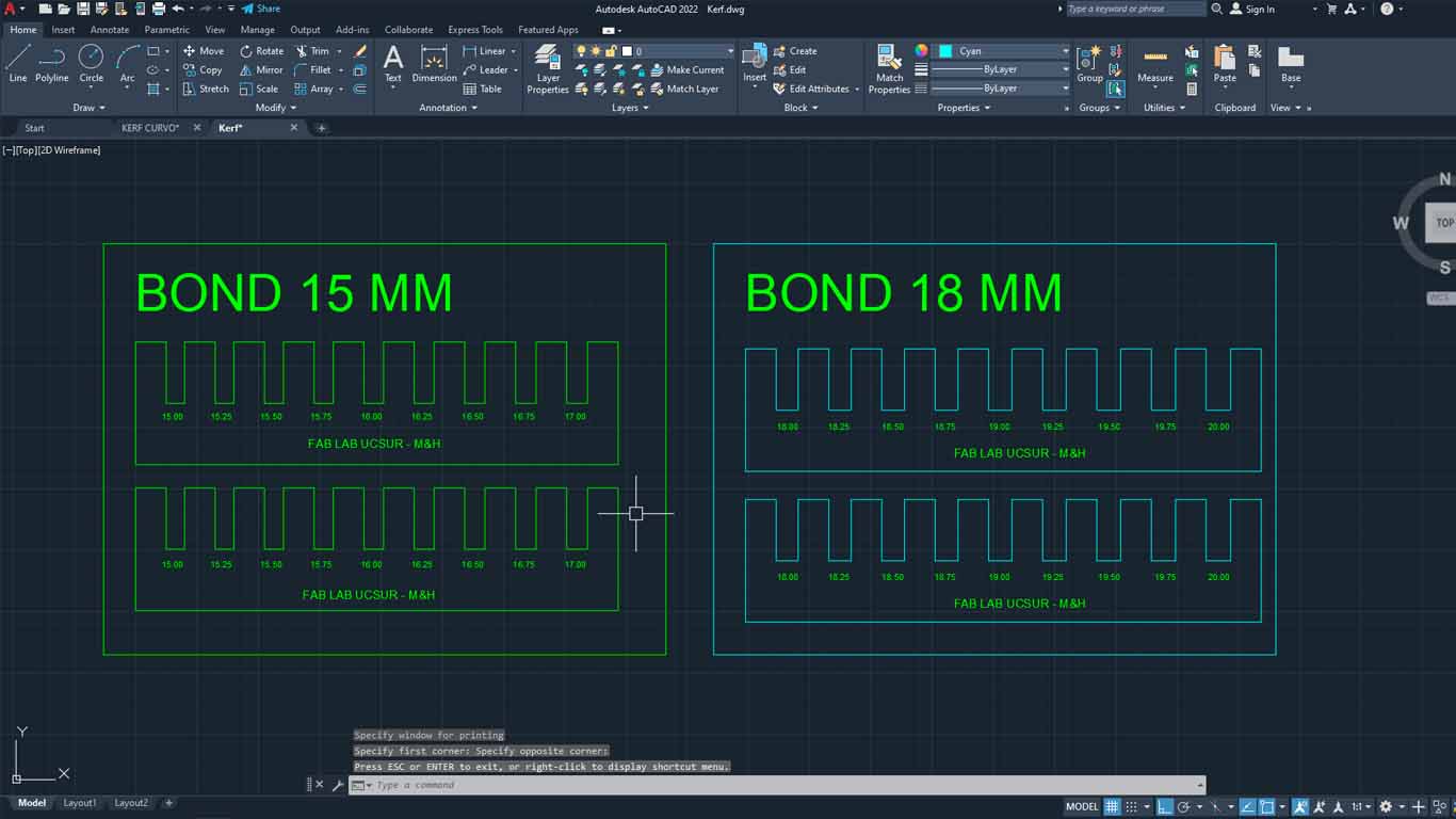
Later, we did was make the drawing in AUTOCAD where we made the bond taking into account the thickness of the material, which is 15 mm, and we gave each section a value of +0.25 mm to see what measurement was appropriate for a correct fit. . Here the process:
Here is a table with the characteristics used in the VCARVE PRO for cutting the comb.
| NUMBER OF PASES: | 3 |
|---|---|
| SPLINDE SPEED: | 18000 RPM |
| RATE: | 5000 mm/min |
| CHIP LOAD: | 0.1389 mm |
| CUTTING AREA: | OUTSIDE |
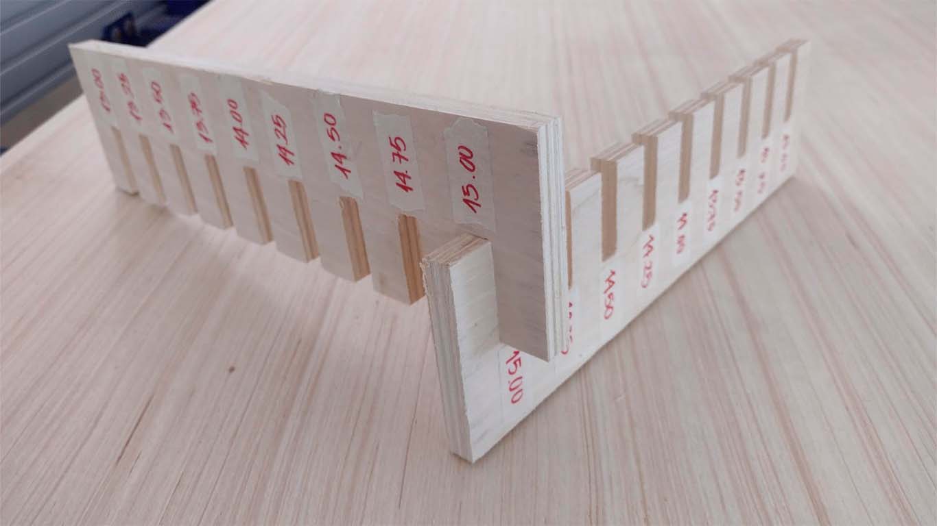
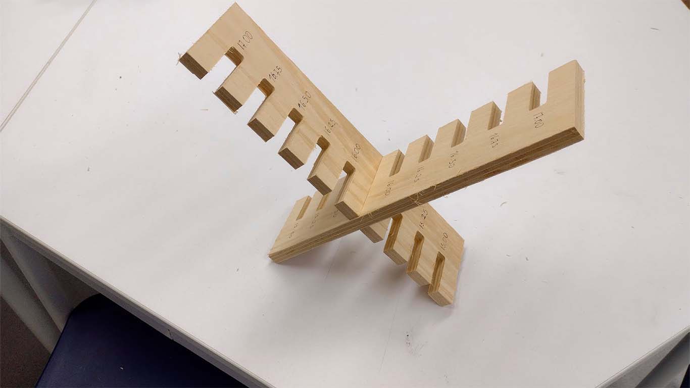
After cutting both combs, we can analyze and verify that the best joint for joints that are like this is for the cuts to have +0.75mm of the thickness of the material. In this case, for the 15 mm material, the ideal cut would be 15.75 mm for a better fit of the pieces.
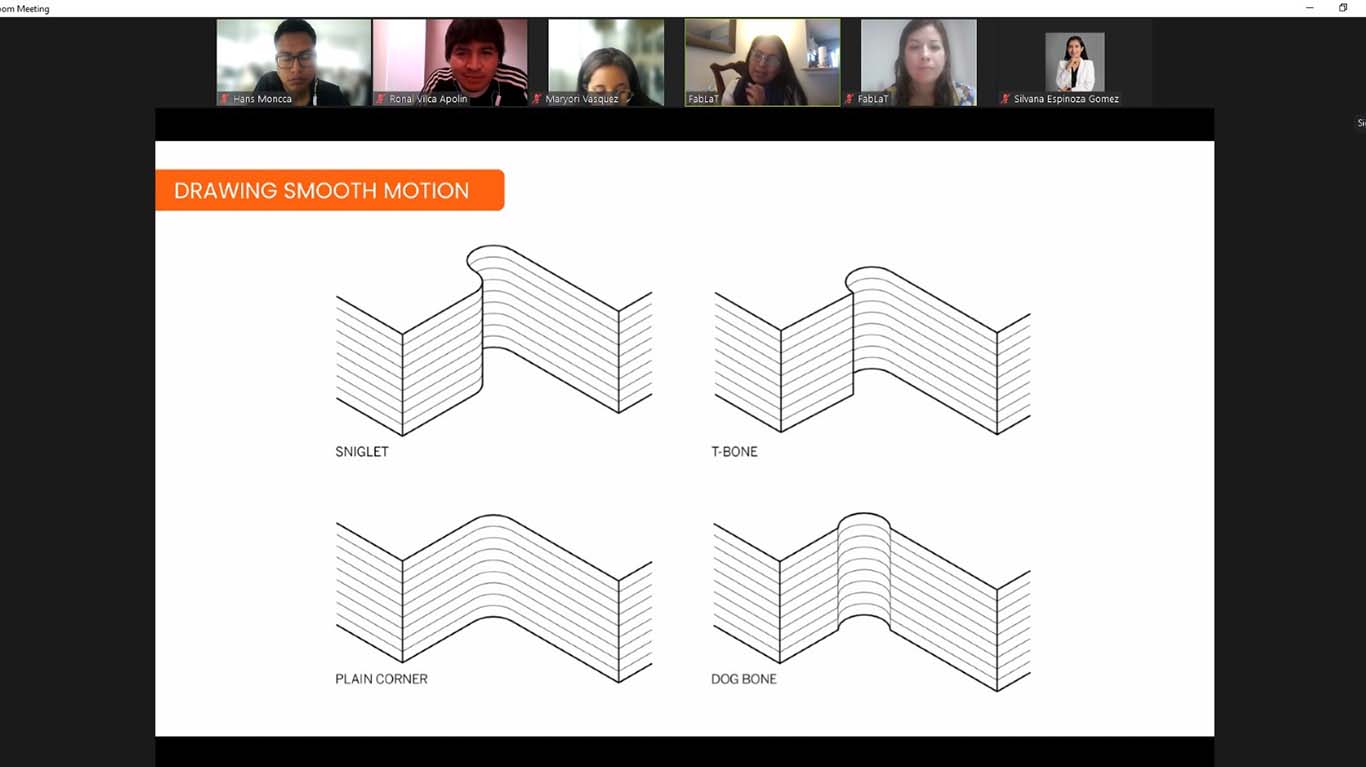
One observation, we forgot to make the dog bones and the chamfer that the corners must have so that they can be joined more easily.
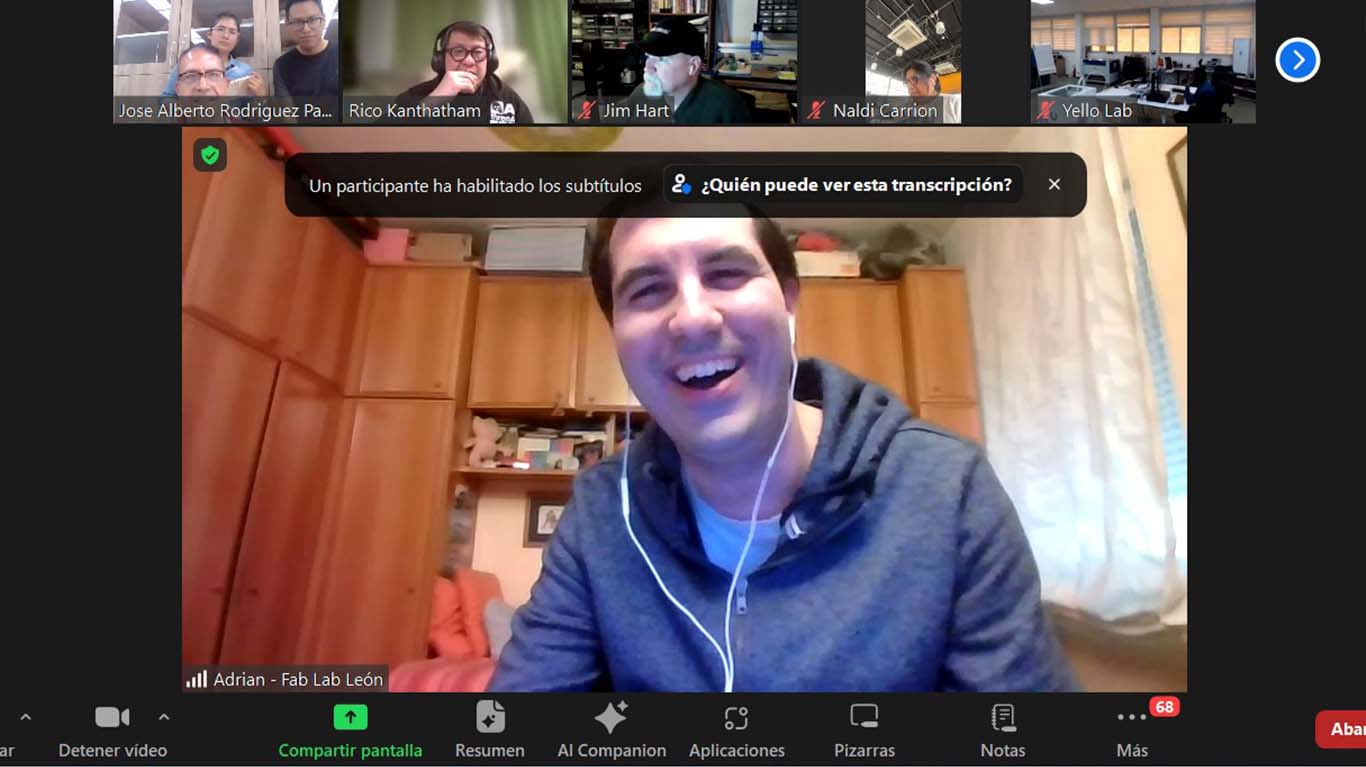
Before moving on to the next test, we joined the GLOBAL OPEN TIME as a group, where they were explaining how we could do the tests. We were grateful to Adrian and Rico for the explanations and we showed them our comb, but they recommended that we make chamfers and they observed the dog bones in each of them. The truth is that many thanks to them and also to Jose Alberto for sharing the photo.
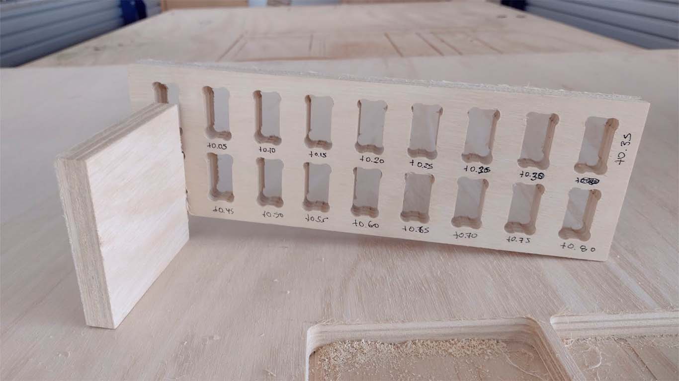
DOG BONE AND HOLE TEST
The second test is the dog bone and the hole. The idea of the test is to know what size is needed for the pieces to fit well in the holes. The DOG BONE test is to make it easier for us to insert the pieces between them and to ensure that the corners do not have problems, this mainly applies to the FEMALE pieces. On the other hand, the hole test is to know what size the female piece will be so that the MALE piece can enter without problems and without damaging the material.
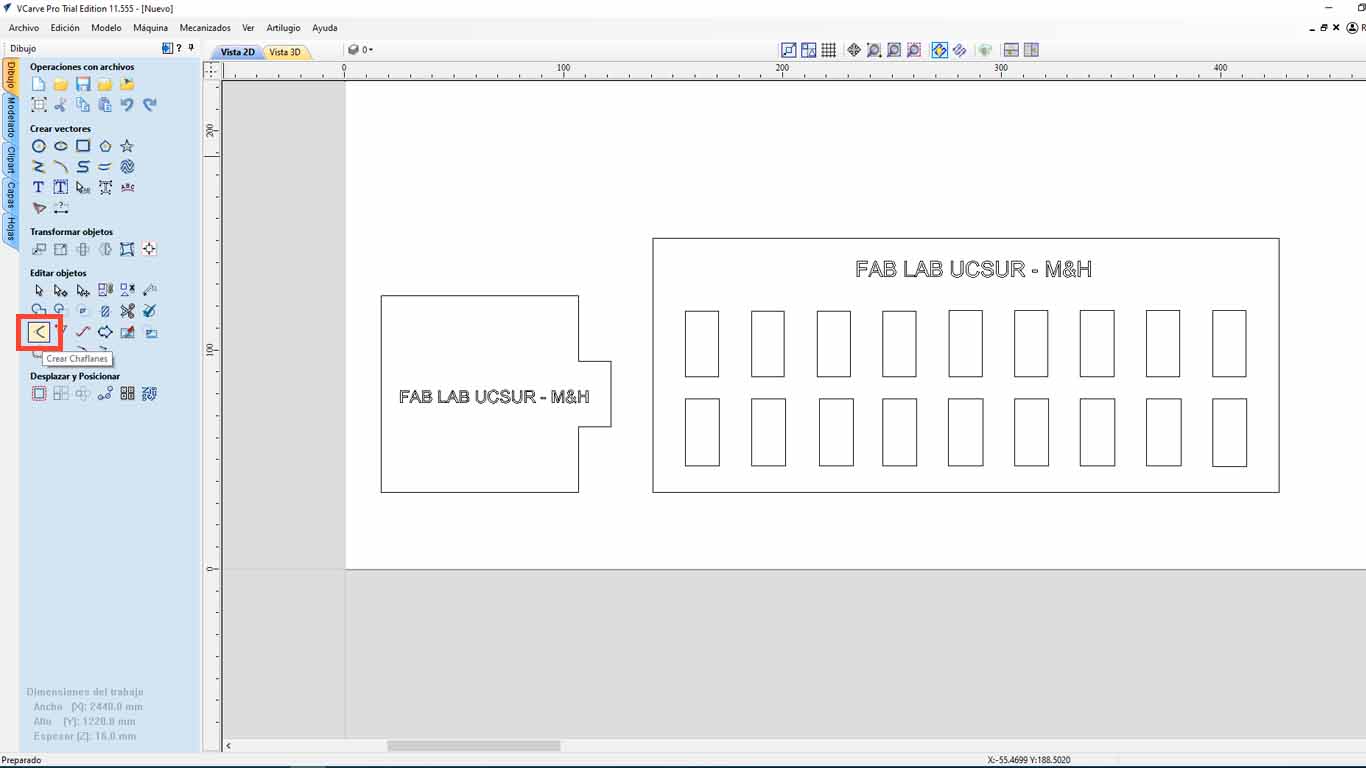
To give the DOG BONE shape, we can do this in the VCARVE PRO after having the pieces designed. When importing, we go to the CREATE CHANFLES button.
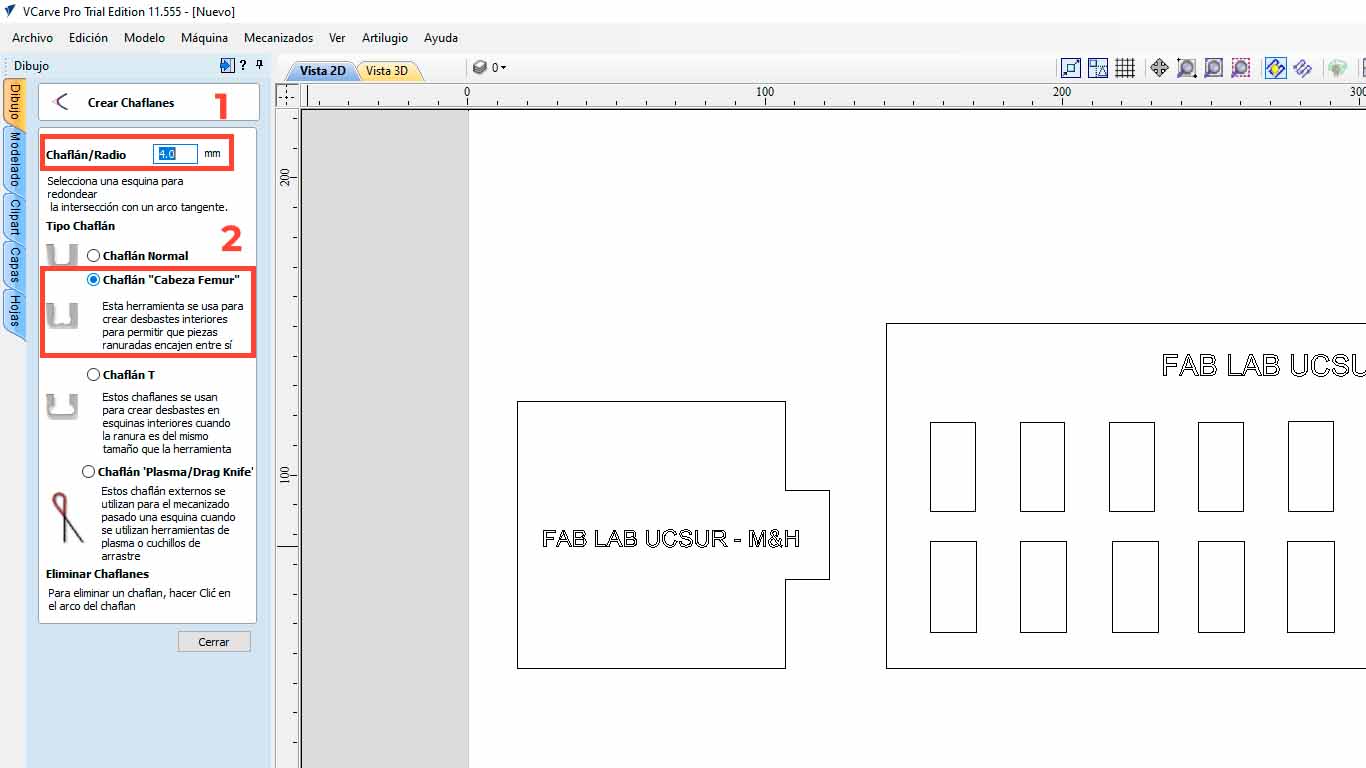
Here we configure the size of the radius that we want the corners to have, in this case we will use 4 mm and we will also choose the FEMUR HEAD , which gives it a bone shape that is better for wooden pieces.
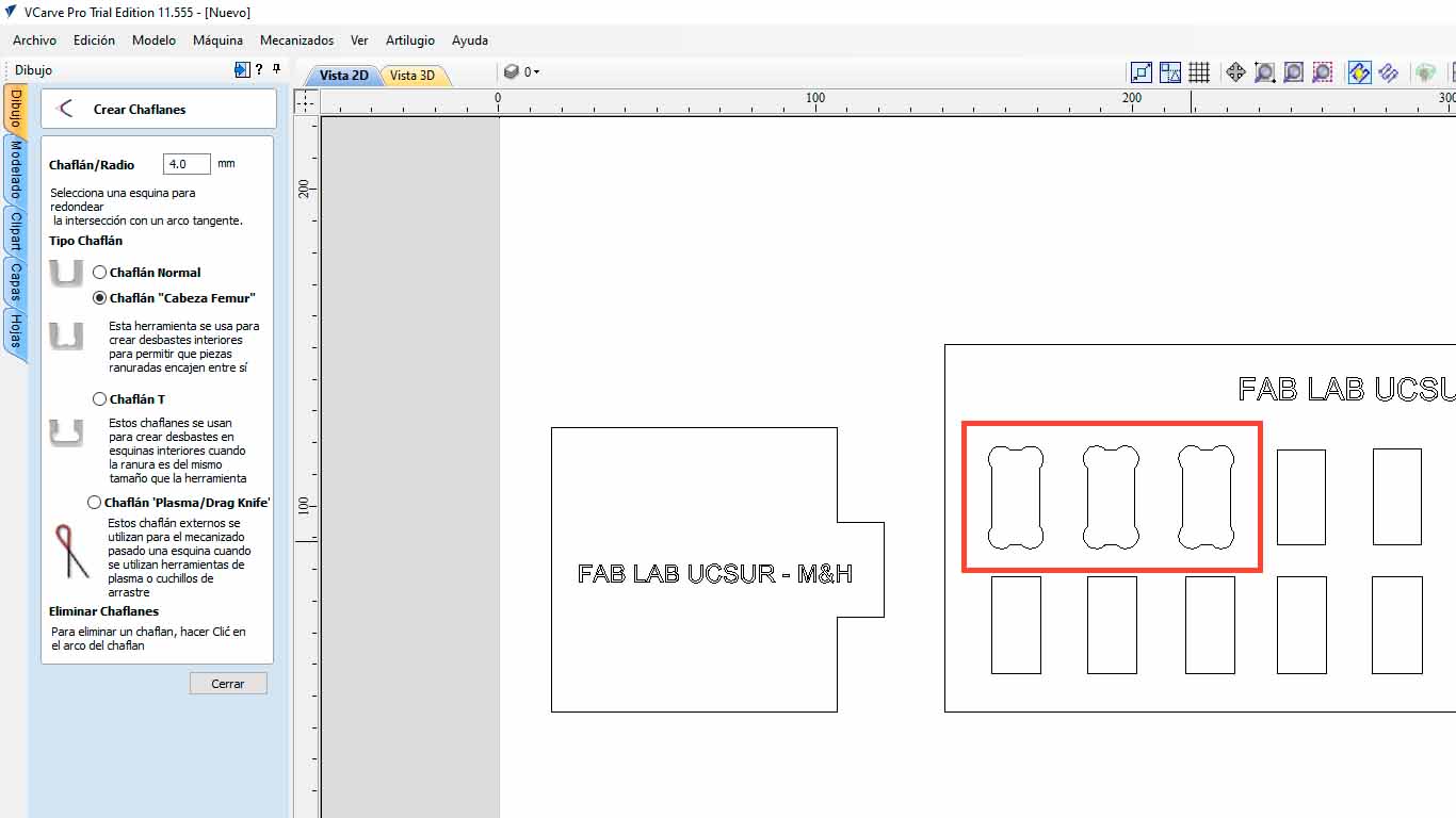
Then we click on the corners that we want to make the corner change to DOG BONE and we will have done it.
After modifying all the holes in the imported file and sending it to be cut, we can see the difference and this process is important so as not to damage the materials and the pieces fit better. Here I leave the table of the characteristics taken in the VCARVE for the cut and the cut piece.
| NUMBER OF PASES: | 3 |
|---|---|
| SPLINDE SPEED: | 18000 RPM |
| RATE: | 5000 mm/min |
| CHIP LOAD: | 0.1389 mm |
| CUTTING AREA: | INSIDE |
In the following image we can see that the MALE piece easily fits into the +0.40mm hole, that is, if the piece has a thickness of 15 mm, we need the female piece to have a hole of +0.40mm, in this case 15.40mm. And we add this same calculation to the height of the female piece, in order to obtain a suitable female piece and we can have a perfect fit, without the male piece entering with too much force or coming out easily. For this the test helps us a lot.
CURVATURE TEST
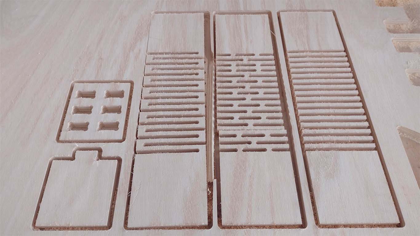
The next test is to convert a rigid element such as plywood into curved elements using patterns that are cut into them and we can achieve different curvatures. For the next test we perform 3 patterns and be able to see the difference between them regarding curvature, flexibility and rigidity. Here I will show the characteristics that each of them have and what the advantages are to be able to achieve any curved object in wood.
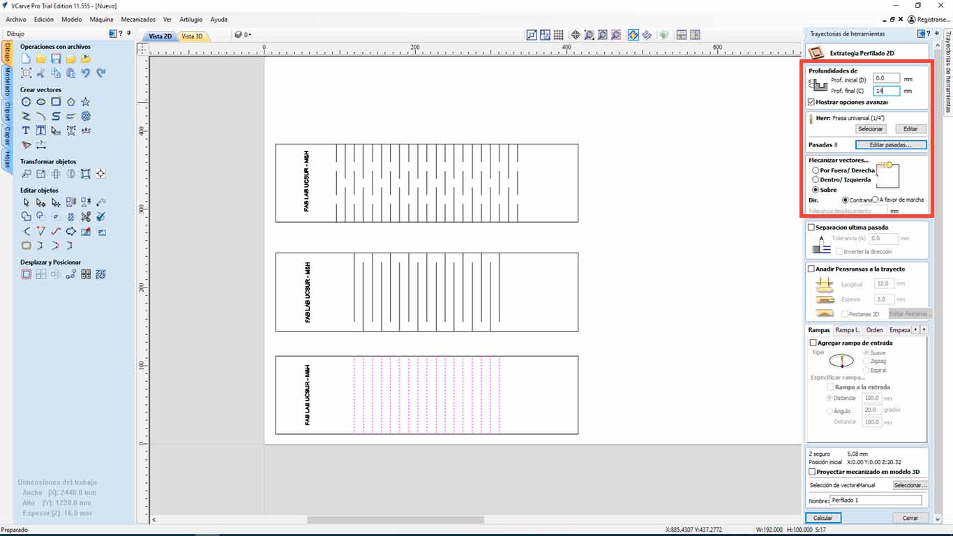
First, we import the curvature model into VCARVE PRO, then we carry out the steps mentioned above and when configuring the cut, we have to differentiate the types of cut, depth and side. For the perimeter of the tests, we will use the depth of 16mm, and the cut on the OUTSIDE.
| NUMBER OF PASES: | 3 |
|---|---|
| SPLINDE SPEED: | 18000 RPM |
| RATE: | 5000 mm/min |
| CHIP LOAD: | 0.1389 mm |
| CUTTING AREA: | OUTSIDE |
| DEPTH: | 16 mm |
For tests type 1 and 2, we have to make the drill cut above the line, so we will choose OVER THE LINE, where the drill will pass through the designed lines that have a separation of 12 mm.
| NUMBER OF PASES: | 3 |
|---|---|
| SPLINDE SPEED: | 18000 RPM |
| RATE: | 5000 mm/min |
| CHIP LOAD: | 0.1389 mm |
| CUTTING AREA: | OVER THE LINE |
| DEPTH: | 16 mm |
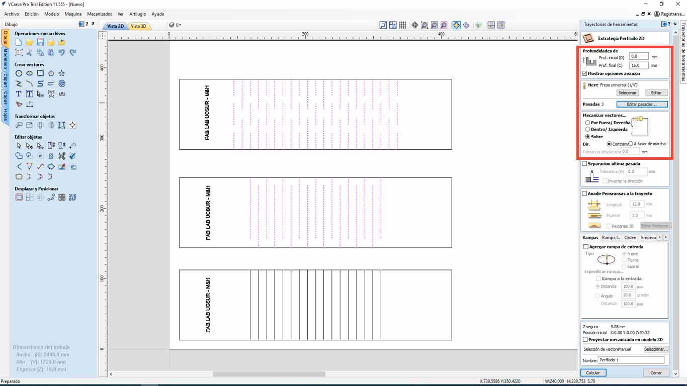
For test type 3, we only have to cut 14 mm deep since we do not want it to cut the entire thickness of the material, but we only want it to leave a little material so that it can be folded. On the other hand, the cut will also be on the designed line and 12 mm apart.
| NUMBER OF PASES: | 3 |
|---|---|
| SPLINDE SPEED: | 18000 RPM |
| RATE: | 5000 mm/min |
| CHIP LOAD: | 0.1389 mm |
| CUTTING AREA: | OVER THE LINE |
| DEPTH: | 14 mm |
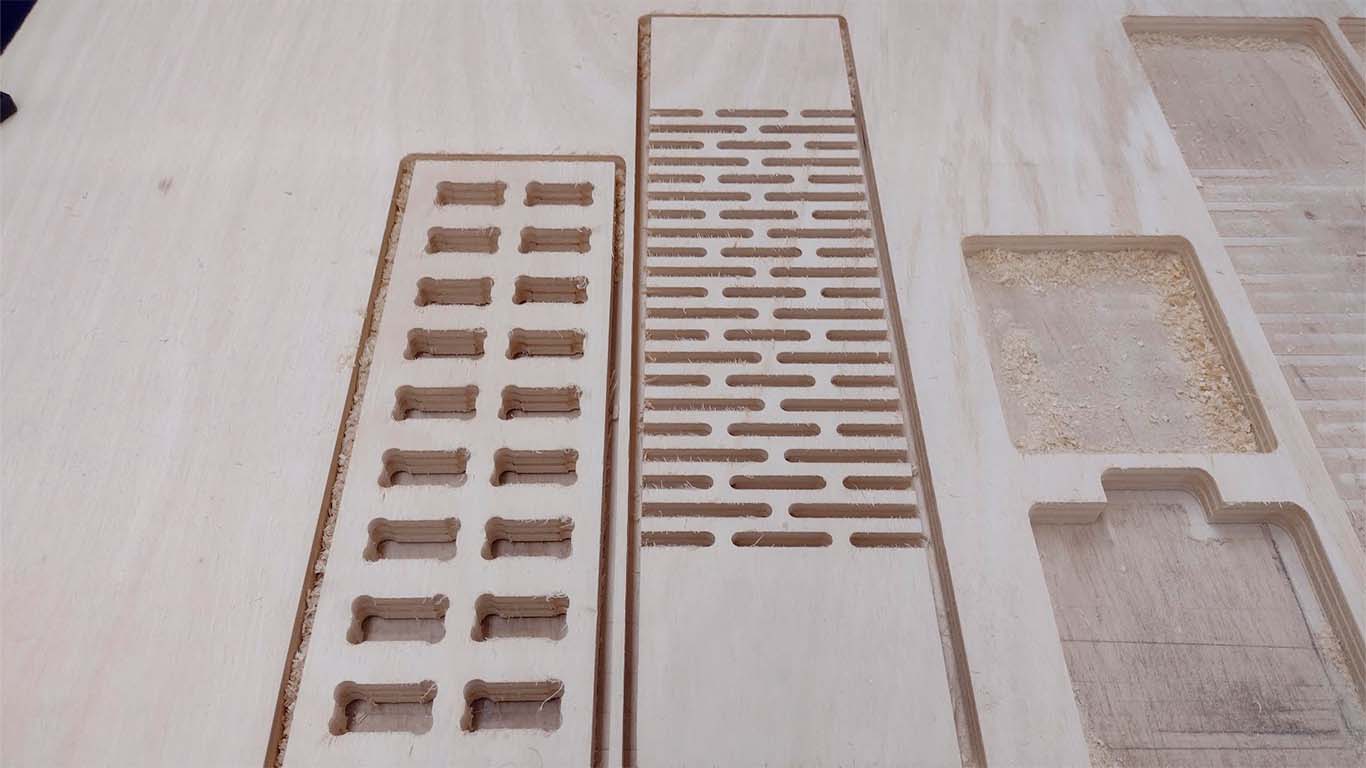
Here we have a screenshot of the cut achieved by the CNC machine from the curvature tests that we will now apply and see the flexibility that we can find in each type.
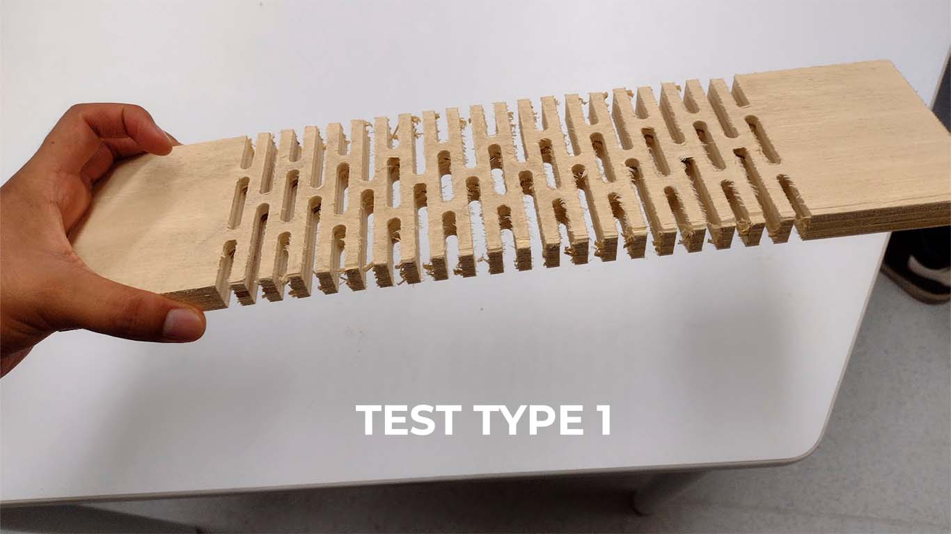
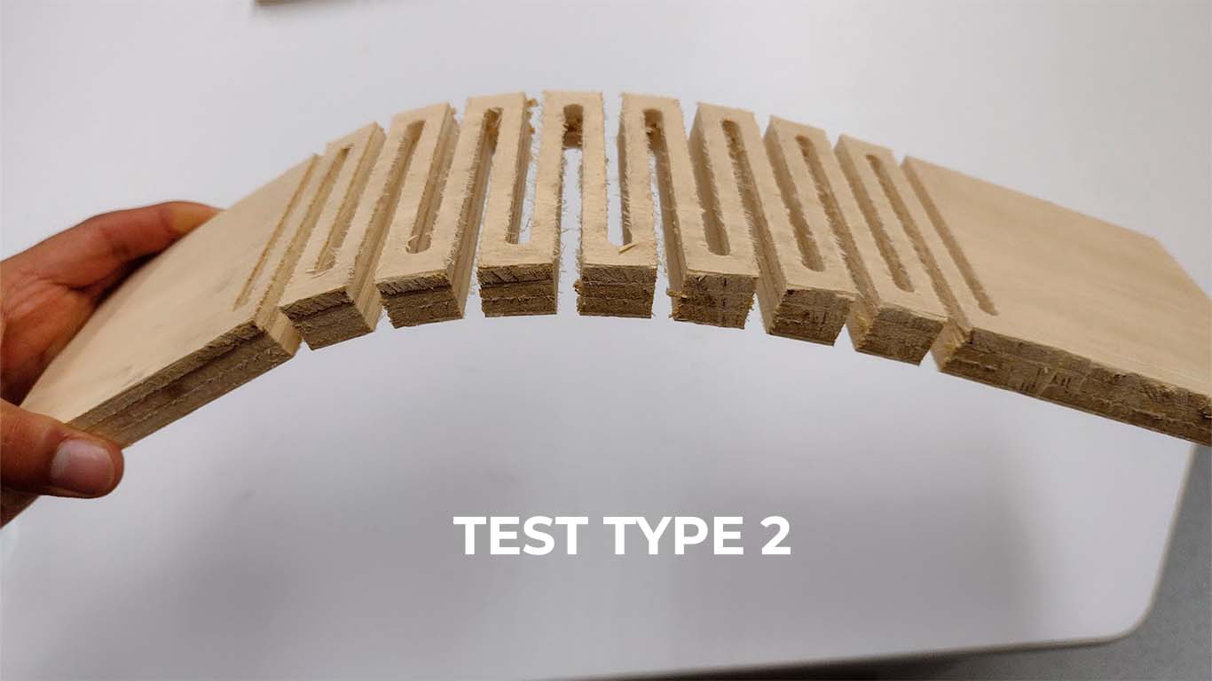
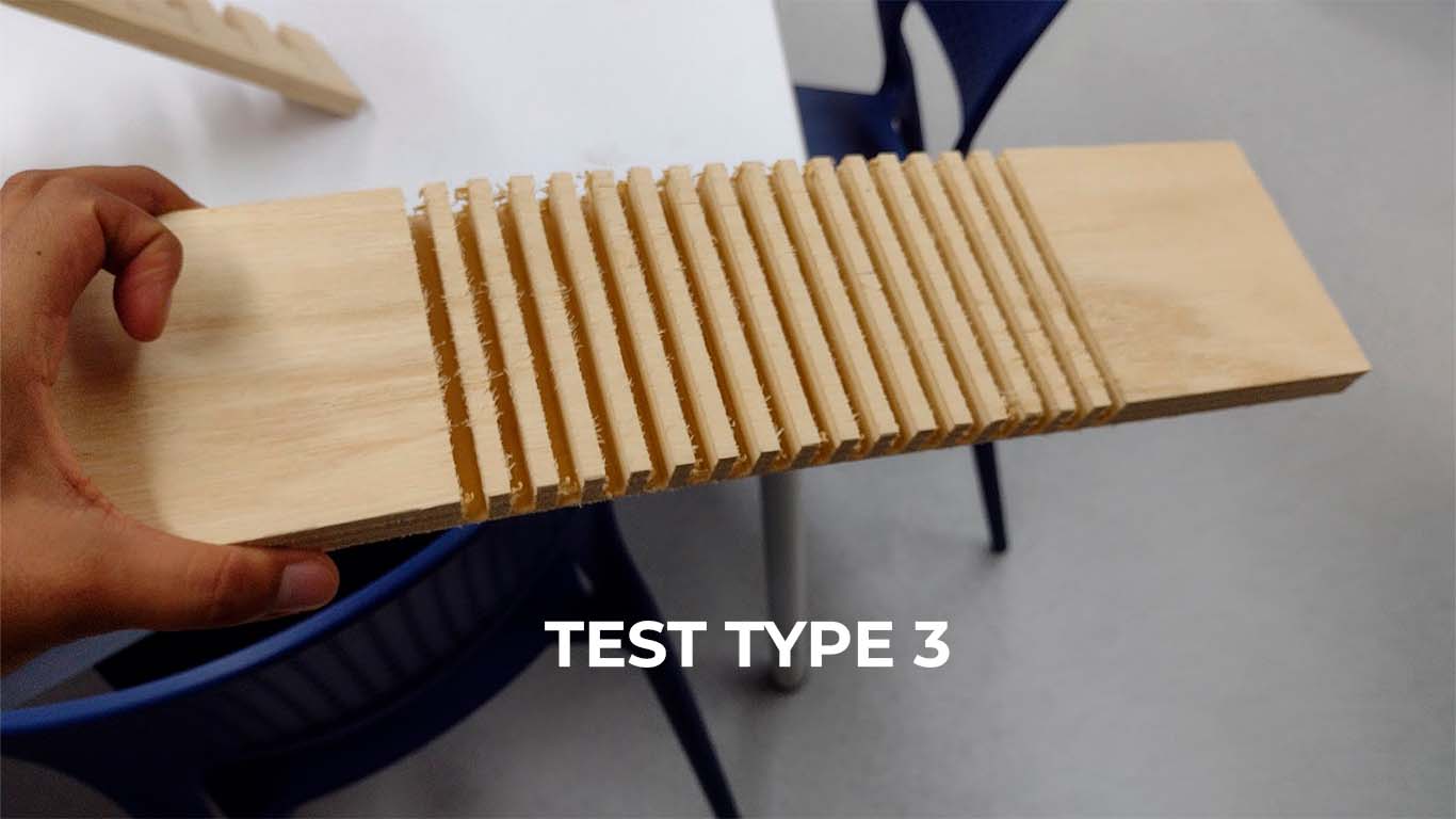
Here is a video of the bending of the wood with the tests carried out. The truth is that I was surprised by how wood can be dubbed using these textures. The type 1 test went wrong because we did not notice that there was a double line in the file that caused the test to be cut, so we repeated it and it worked.
INDIVIDUAL ASSIGNMENT
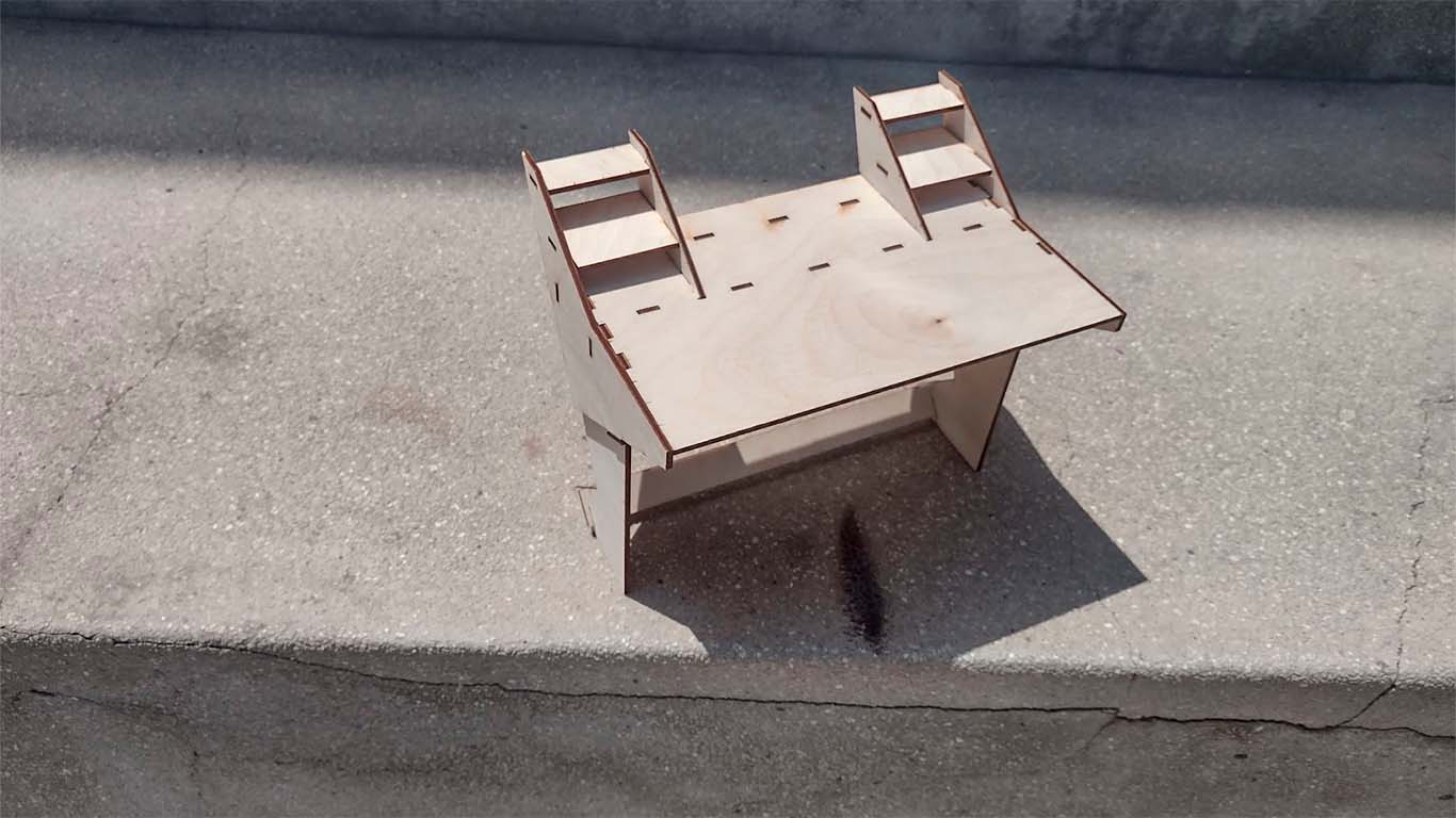
MAKING SOMETHING BIG - GAMER WORK TABLE
DESIGN 2D AND 3D
For individual work, I made my desk for the FAB LAB because the one I have is very small and with only the computer monitor, mouse and keyboard it gets crowded and it is difficult to work. For this reason, I decided to design a table that has a futuristic character and that is why I use the gamer concept that has technology and innovation in its words. From there, I started drawing some sketches and got a design that I really liked.
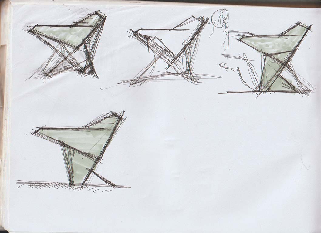
After sketching and getting my idea, I wanted to transfer it to 3D programs and worked with FUSION 360. Here the doubt made me waste time thinking about the design, I wanted to make some changes and here I show my 4 design proposals.
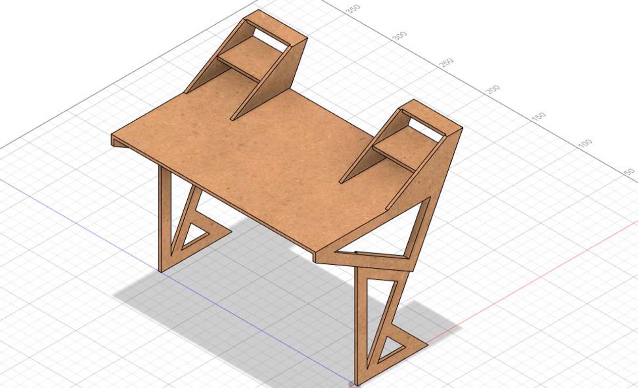
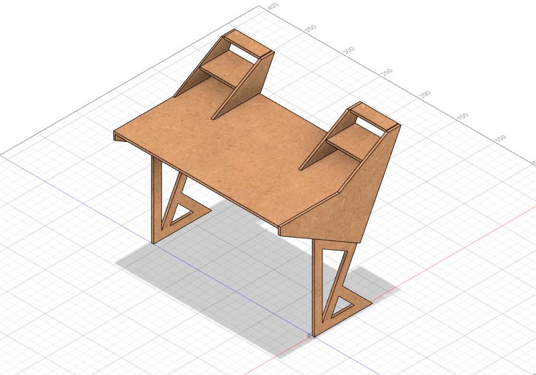

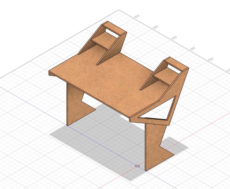
Here I had to decide on a design that seemed functional to me and could work. For this reason, I stayed with option 3, which seemed very compact to me and at the same time had the characteristic of being modern, which was what I was looking for and was not the typical table.
MODEL
Then, I decided to make a small 1/5 scale model of my chosen proposal. I made it in 3 mm plywood that we had worked on in week 3. I remembered the KERF and the TESTs carried out that week and applied it to obtain the model and analyze if it had stability problems or the design needed to be improved.
EXPLODED AND CONFIGURATION IN VCARVE PRO
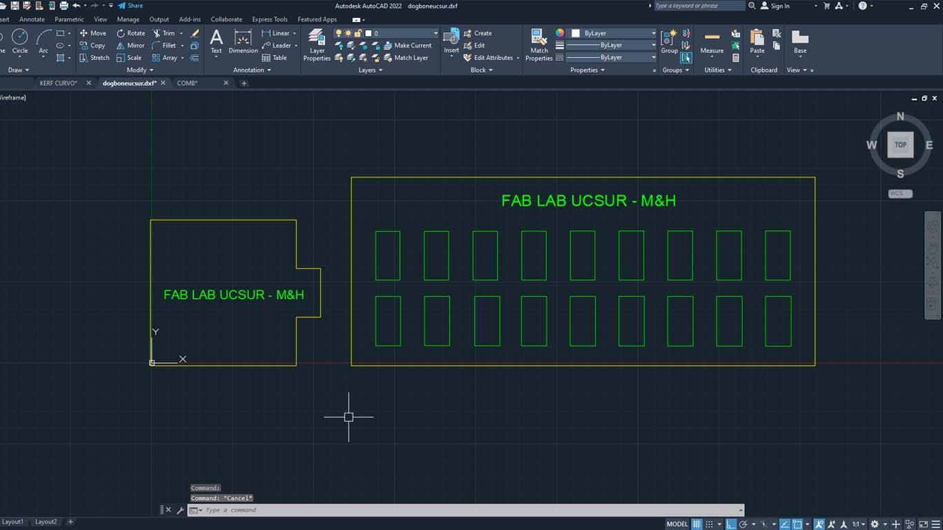
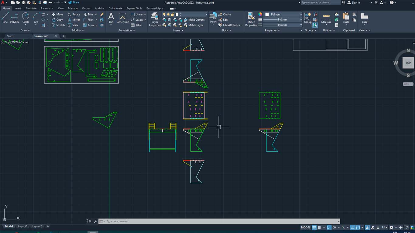
After analyzing and correcting the errors obtained in the model, I decided to start breaking down the parts of the table. I first did it in AUTOCAD, where I worked with mm and began to locate all the pieces that make up the table and then import it to VCARVE PRO.
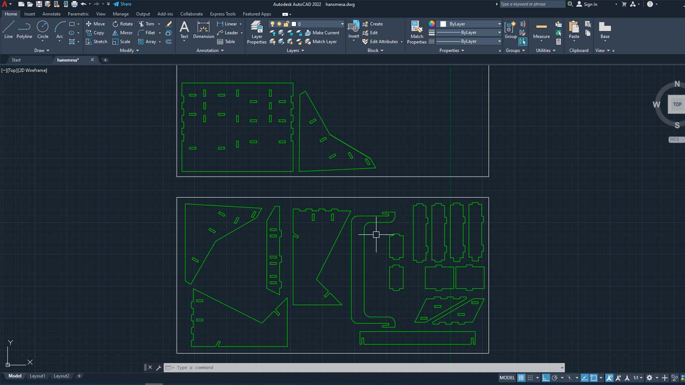
After importing into VCARVE PRO, I started selecting the female holes of the pieces and started turning their corners into DOG BONE so that the pieces fit together better. I want to mention that in AUTOCAD the size of the holes was changed with the appropriate measurements mentioned in the tests.
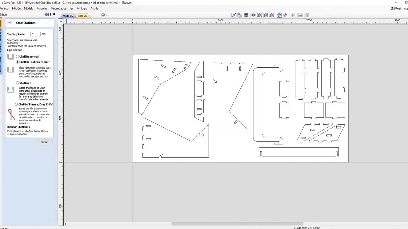
Then we select all the ones that will be FEMALE holes and configure them. First we start by setting the speed of the cutter and then choosing that the cut will be INSIDE. Finally, we get a simulation and check that everything is fine.
| NUMBER OF PASES: | 3 |
|---|---|
| SPLINDE SPEED: | 18000 RPM |
| RATE: | 5000 mm/min |
| CHIP LOAD: | 0.1389 mm |
| CUTTING AREA: | INSIDE |
| DEPTH: | 16 mm |
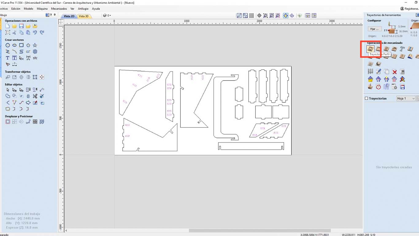
Then we start with the cuts of the pieces. First, we select all the pieces so they can be cut.
After that, we configure the number of passes that the CNC will have so that it can cut the material, remember that we are working with a thickness of 16 mm, 1 mm thicker than the real material. So for this project, we will configure in 3 passes.
Then, the next step is to choose which side the cutter will run through for the cut, in this case as it is the perimeter of each piece, we will choose OUTSIDE.
| NUMBER OF PASES: | 3 |
|---|---|
| SPLINDE SPEED: | 18000 RPM |
| RATE: | 5000 mm/min |
| CHIP LOAD: | 0.1389 mm |
| CUTTING AREA: | OUTSIDE |
| DEPTH: | 16 mm |
After reviewing all the configuration aspects, we will have a simulation of the cut that the machine will make. In this case everything was fine and now we will save the trajectories to export to the SHOPBOT program.
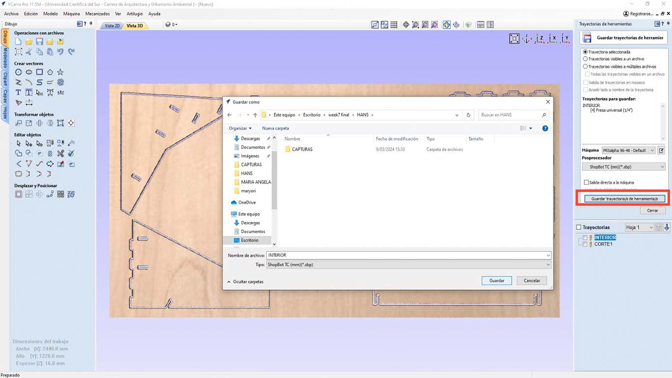
Finally, after saving the trajectories, we open the SHOPBOT program and first import the cut of the INTERIORS or DOG BONES and then EXTERIOR or PERIMETER CUT, this since we have to take into account that if we do it the other way around, the pieces will move and we will not be able to grab them so that the machine does not move them. This can cause damage to the drill bit or SPLINE. Also, do not forget to warm up the SPLINE and configure the X, Y and Z axis, which are important.
After completing all the previous steps. We can start cutting the material. In this case I am using 15 mm PLYWOOD
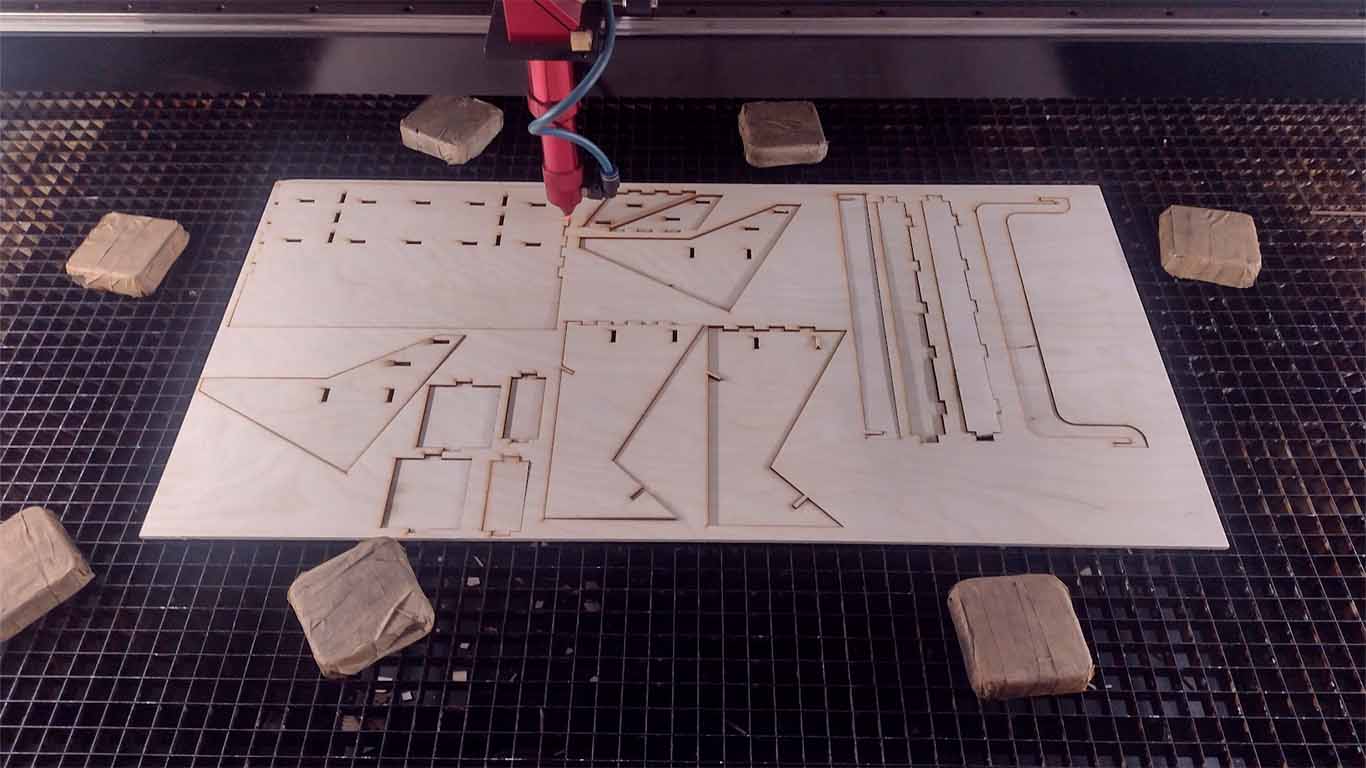
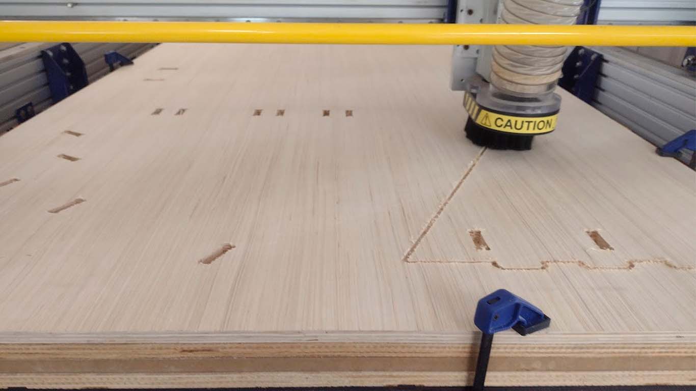
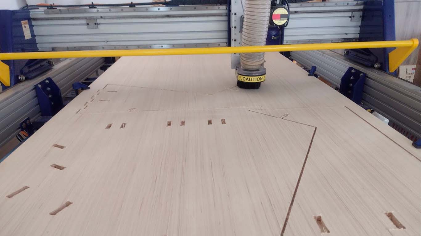
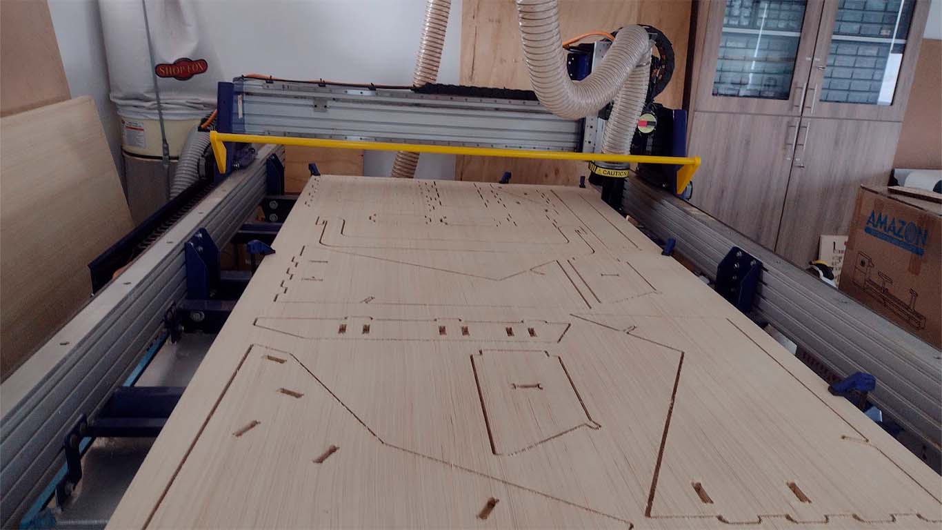
CUTTING ON THE CNC SOMETHING BIG
Before starting to cut, we have to put on our safety equipment, in this case a mask, earmuffs and glasses. Also remember that it is important to always have the machine's EMERGENCY device on hand, so that in the event of any incident you can press the button.
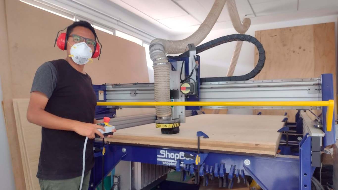
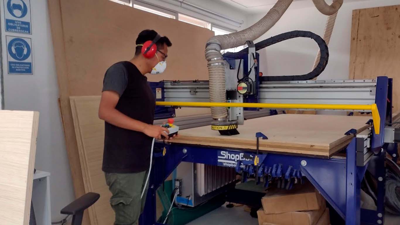
Here are some photographs of how the CNC cut my table.
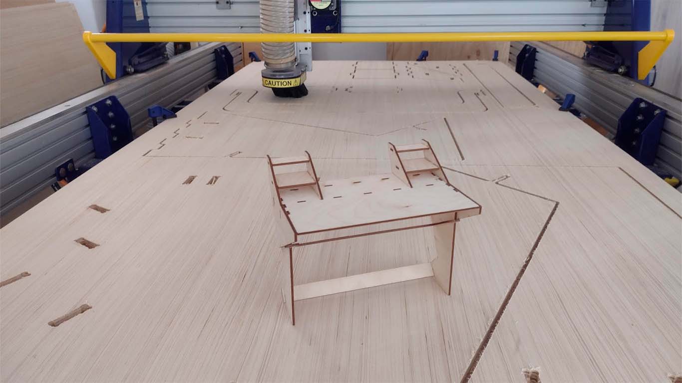
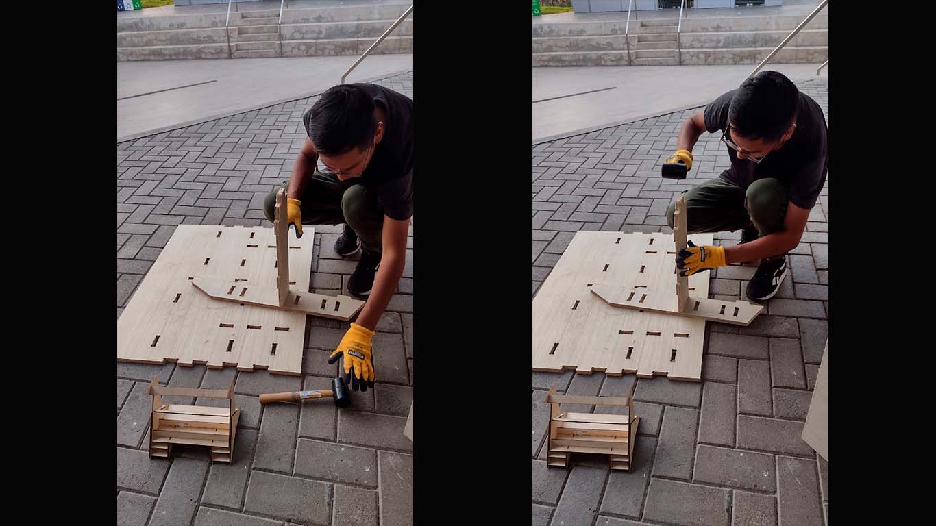
ASSEMBLY THE PIECES OF SOMETHING BIG
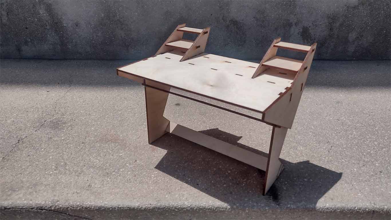
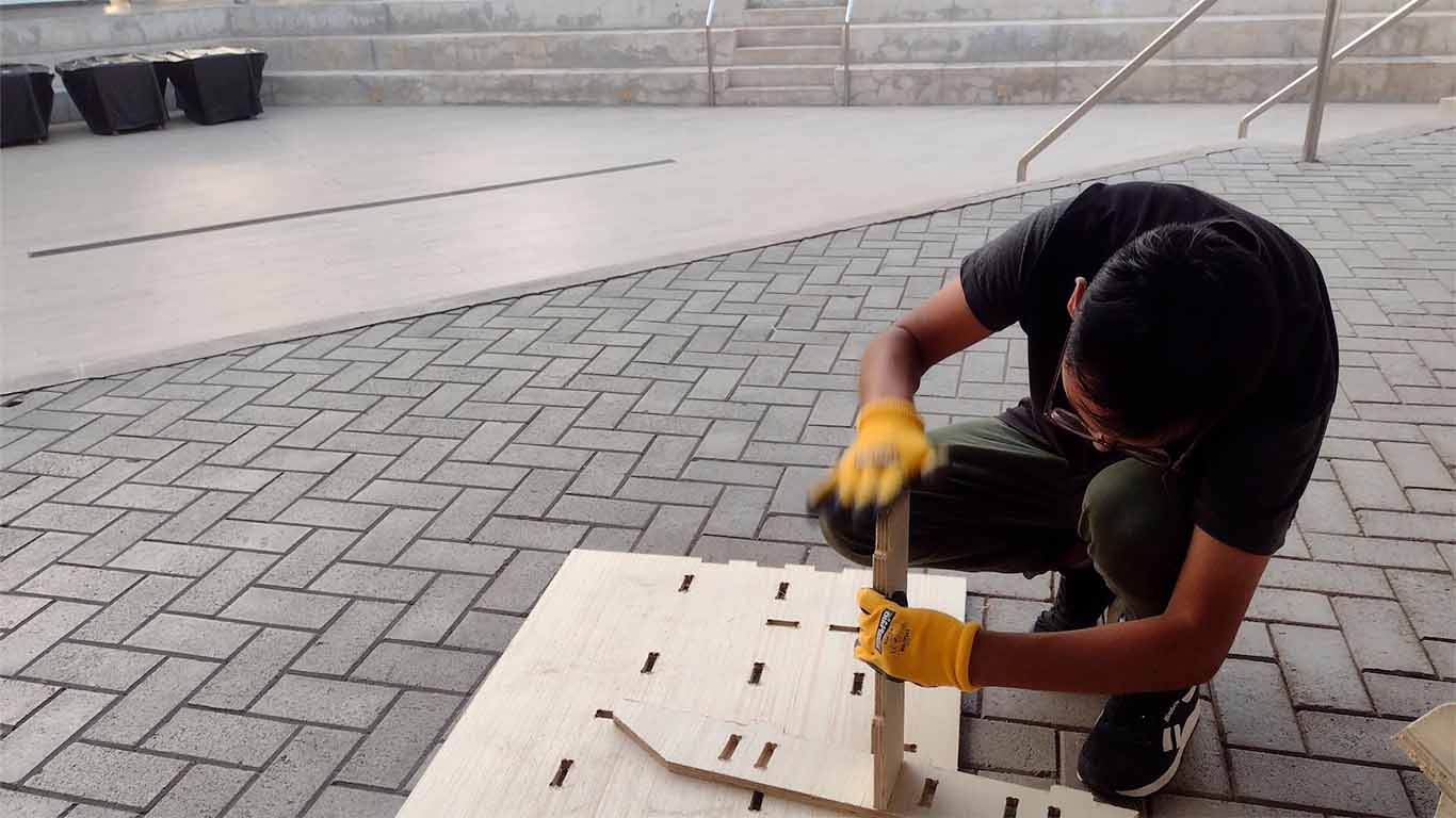
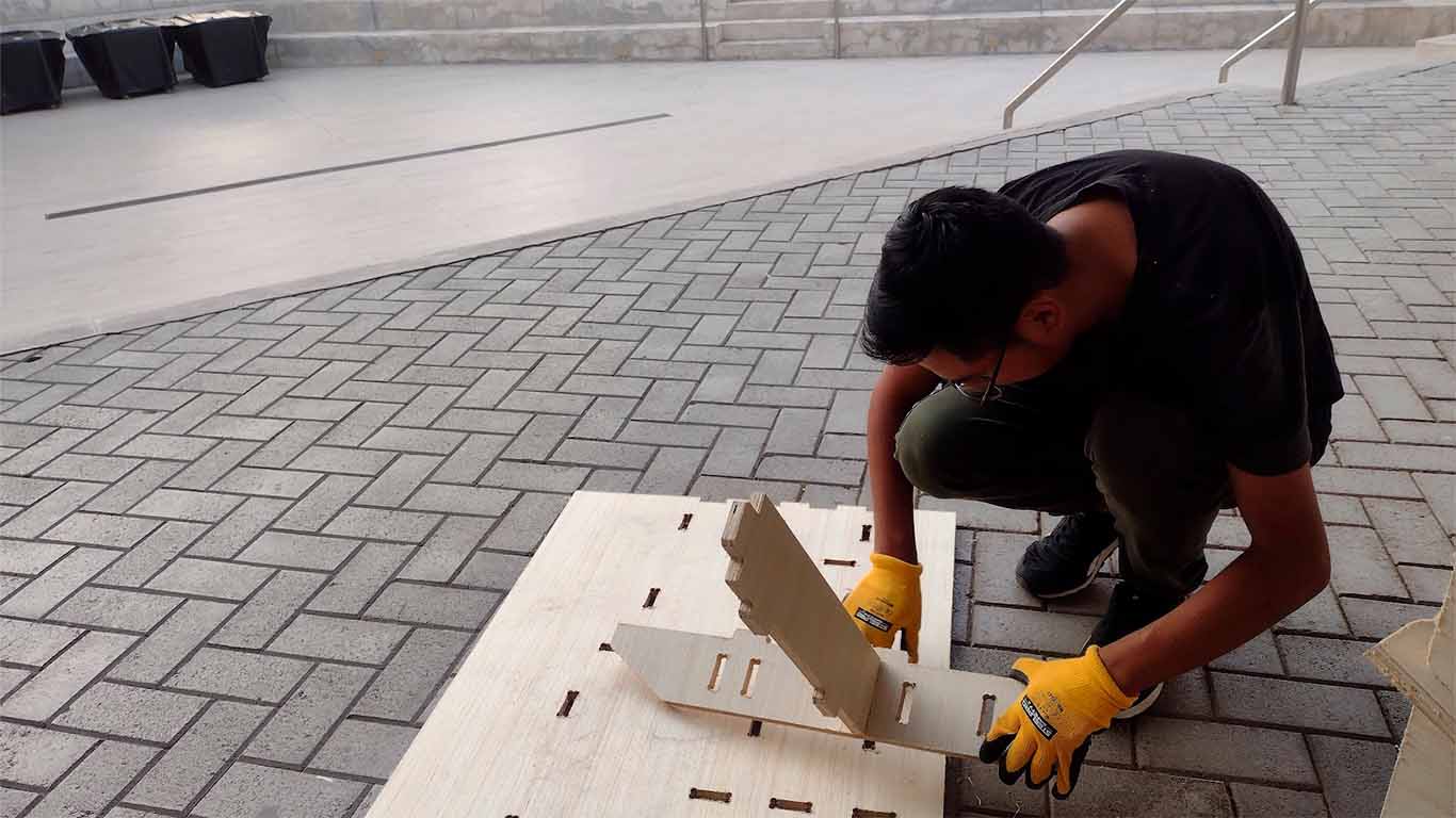
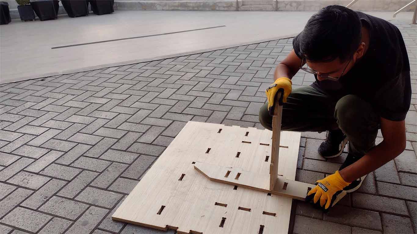
After cutting all the pieces, I began to assemble the cut pieces and at first it was difficult because of the joints and the fact that some holes needed to be sanded. On the other hand, the ground where I was working was uneven and I didn't understand what was happening, so I decided to go to the university patio to work. All the pieces went in without complications. Here are some photos of the assembly.
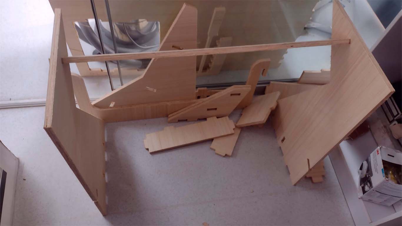
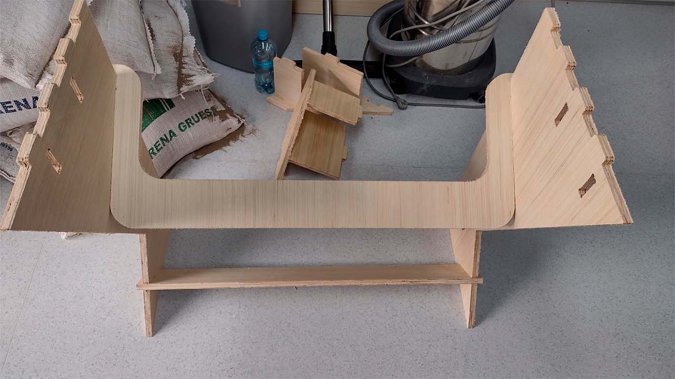
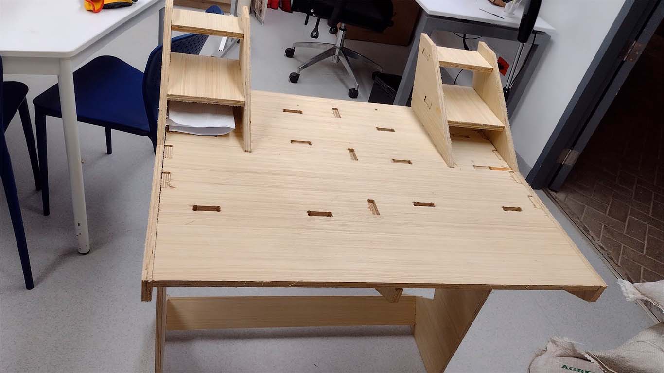
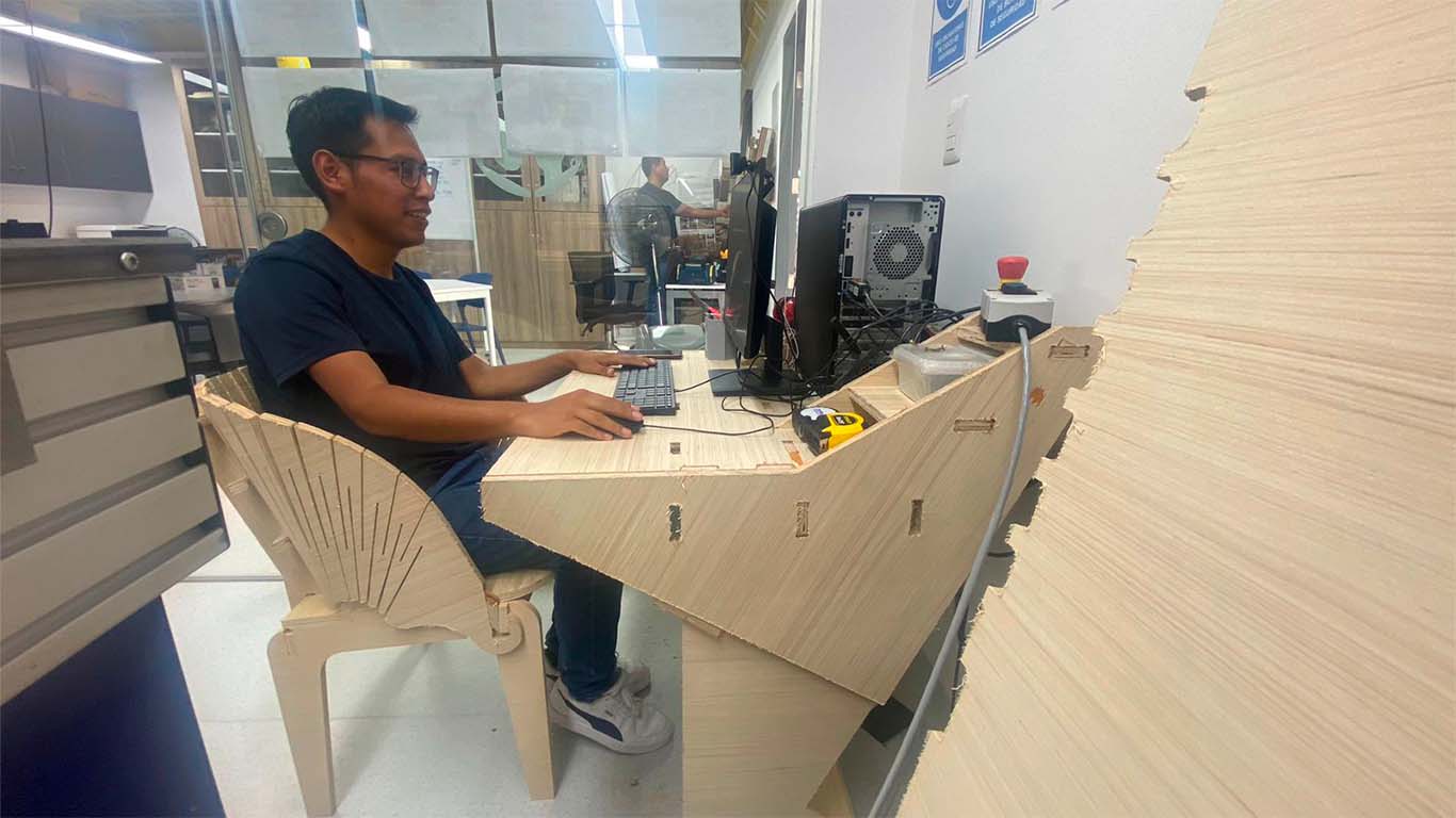
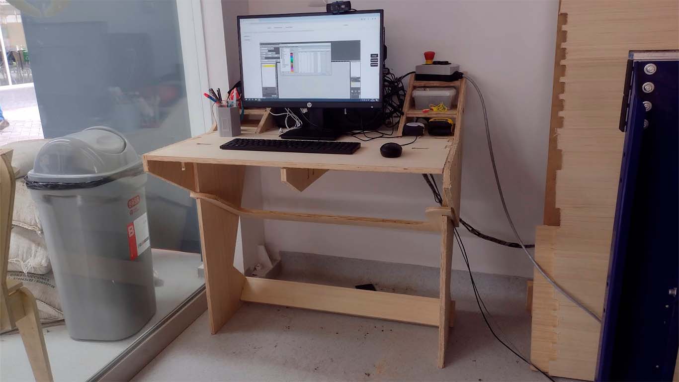
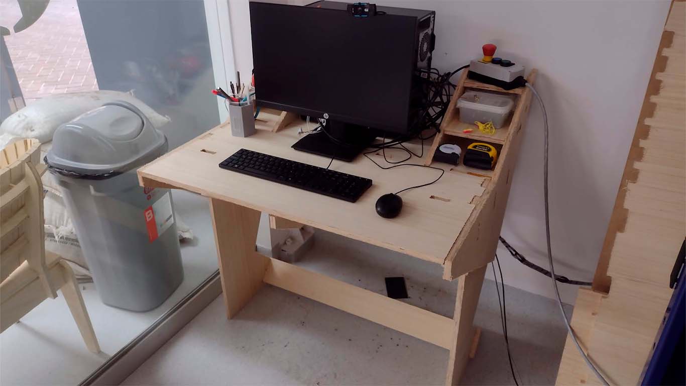
FINAL RESULT
I feel the final result turned out very well, although the table part was a little aesthetically pleasing. I think I worry a lot about stability and compactness rather than design. The truth is that I really like the shape, but there are some things to improve to achieve a true design. I liked it and the truth is that I was amazed at how wonderful going from a small scale to a large one is. Thank you FAB ACADEMY
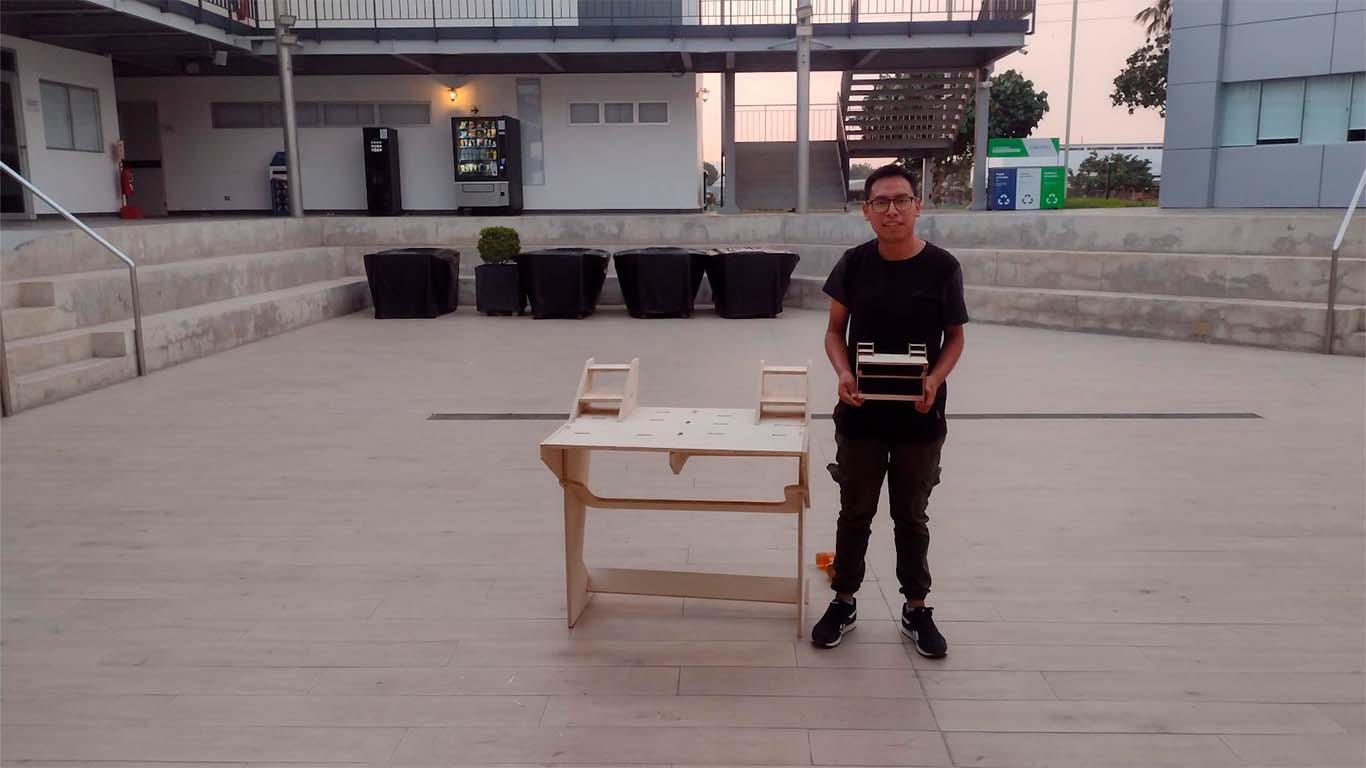
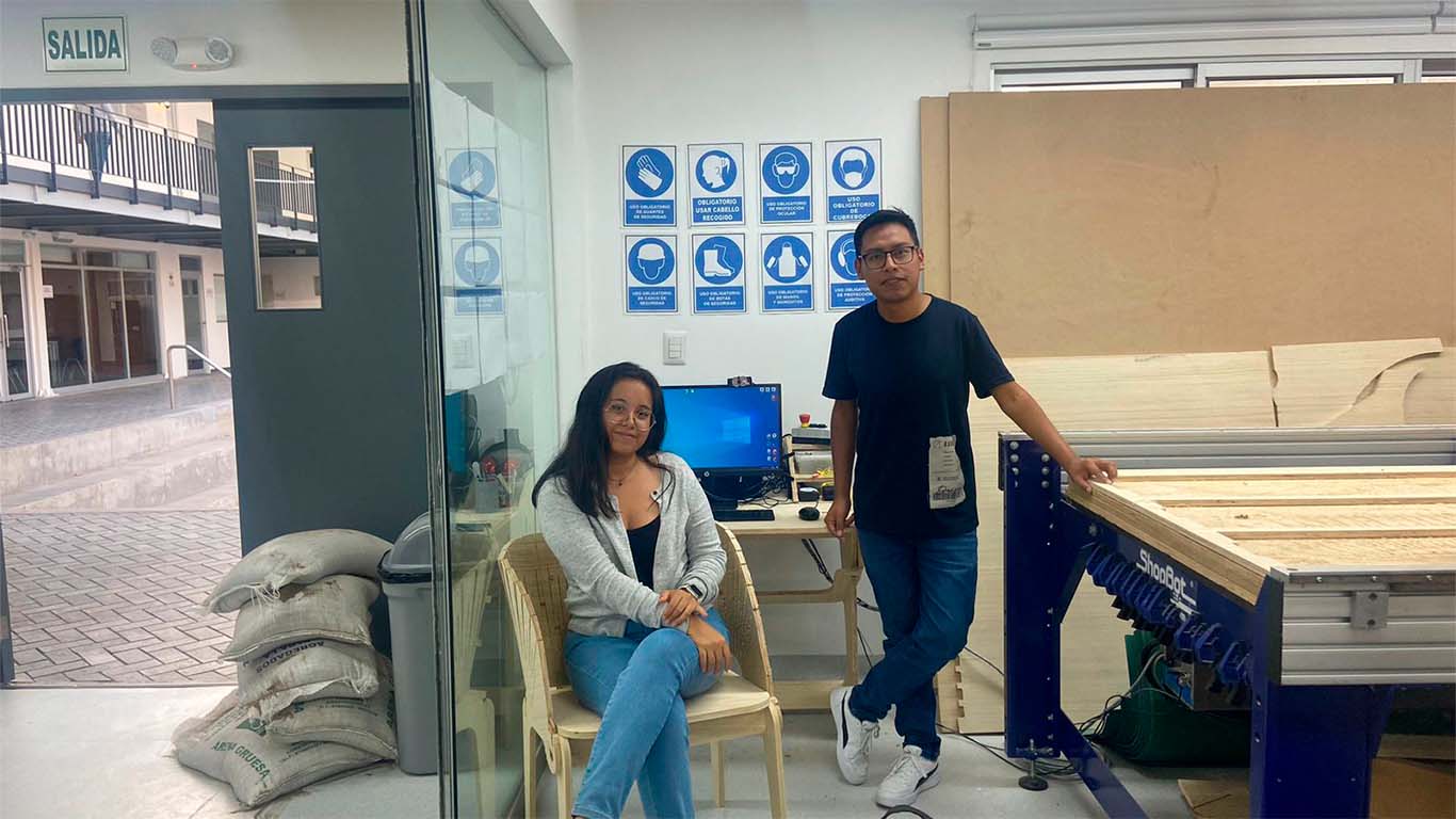
Maybe I forgot to mention it before but my friend Maryori and I had agreed to develop my new work desk for the FAB LAB. The idea was that she would design the chair and I would design the table. In the end each one developed their design and when we put it together we could see that it turned out very well. Now I am happy because I have a new workspace, more spacious and comfortable. As always doing a good job.
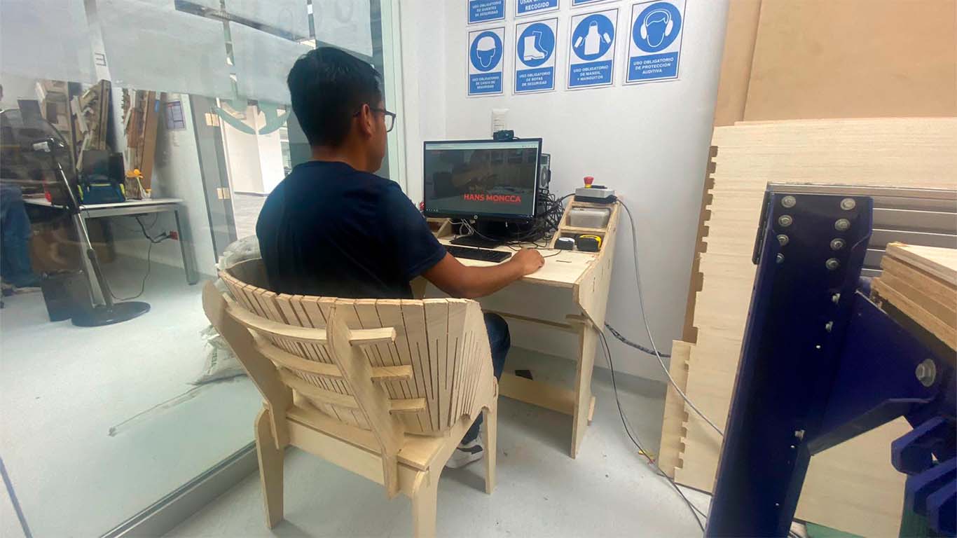
Finally, here is a photograph of us managing to develop interesting things every week and continue learning many things. Thank you Maryori
FILES
Here you can download all the files that I have made for the following assignment: