Networking and Communications
Individual Assignment
Design, build, and connect wired or wireless node(s) with network or bus addresses and local input &/or output device(s)
Group Assignment
Send a message between two projects
Table of Contents
Communication Board
I'm on a tight schedule this week. I have my college internal exams and I took leaves for preparation and attending the exam. So I have one day to finish the assignment. I had referred documentations of previous fab academy students and thought of doing the simplest board possible. I'm using Attiny412 since I haven't used that chip before and as my local output device I'm using LED. This is will be slave board. For master I'll be using the board which I designed before in the previous weeks. I'll be communicating these board using I2C protocol.
I2C
Turns out I2C is one of the topics I had to study for my exam. I'll be attaching the notes in the files section for reference. Here's an overview:
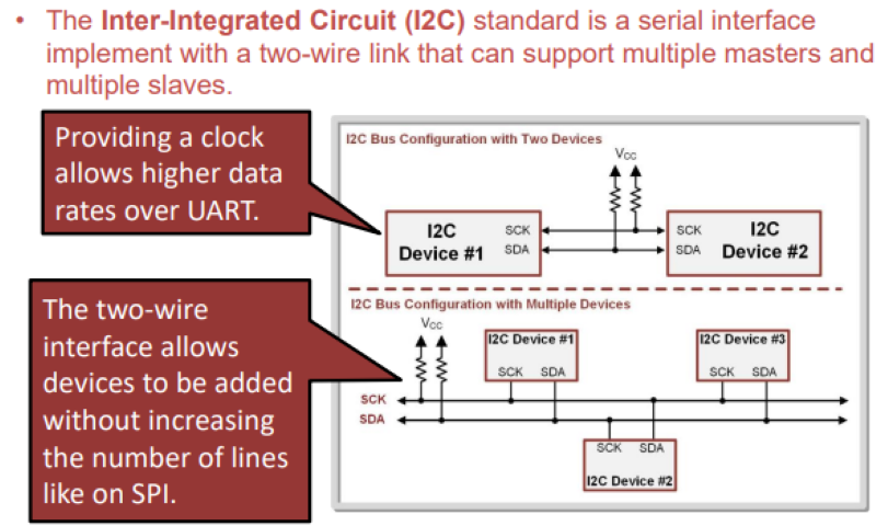
• An I2C link is always half-duplex, meaning that all devices share the
data line with only one device transmitting at any given time.
• An I2C bus ALWAYS needs external pull-up resistors on each of its lines.
• These can’t be implemented on the MCU because the resistor function is only
available when the port is configured as an INPUT.
• Since I2C is bidirectional, we never know whether the pin will be an input or
output.
Slave
I referred documentation of Luis Diazfaes for the design of slave board using Attiny412 using I2C protcol.
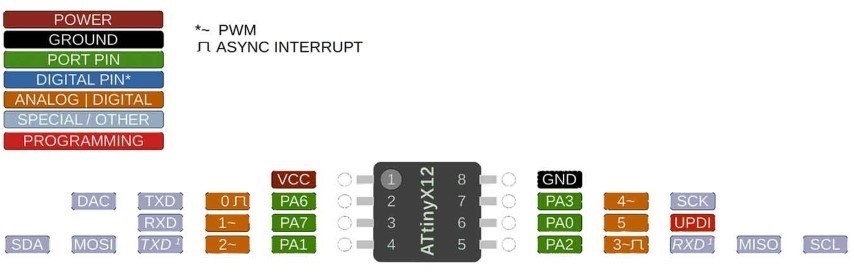
Attiny412
The ATtiny412 is a microcontroller chip manufactured by Microchip Technology. It belongs to the AVR family of microcontrollers and is notable for its small size and low power consumption. The ATtiny412 features 4KB of Flash memory, 256 bytes of SRAM, and 128 bytes of EEPROM. It also includes various communication interfaces such as UART, SPI, and I2C, making it suitable for a wide range of embedded applications. Its small form factor and low power make it ideal for battery-powered devices and other applications where space and energy efficiency are critical.
For my slave board, I'm using this microcontroller. So I used this pin out diagram to understand the microcontroller and use it in my design accordingly.
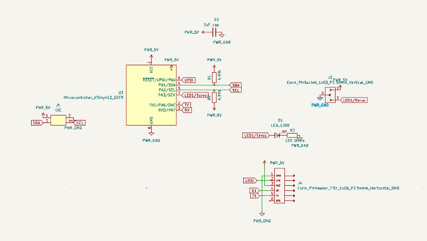
Schematic Design
Here is the design with all components:
PCB Design
- Schematic design is done and next step is the design of PCB layout of the circuit. So I opened PCB editor.
- Next step is set the constraints of the route tracks optimised for the milling bit.
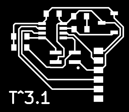
- Here's the result with one slave board with LED and servo motor:
.png)
.png)
.png)
Gerber to PNG
Next step is to export the Gerber file and convert it into PNG for milling. Our FabLab has a special website for this conversion. Visit this website.
Using the options, chose top layer and top cut and generate the png files.
.png)
Here are the files:
.png)
.png)
Production
Next step is the production of the design.
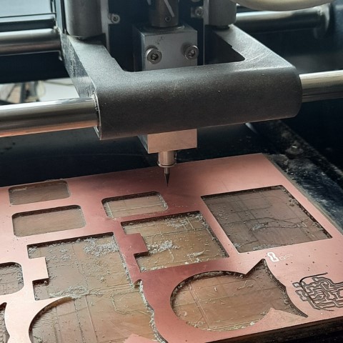
Milling
During week four of electronics production, I was introduced to PCB milling of Quentorres Board by Roland Modela MDX20. Therefore, I'll be implementing the same workflow.
Here's a snap before the milling process
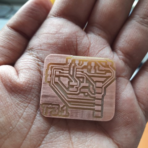
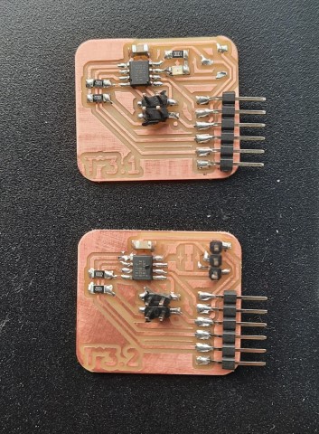
T^3.1 is ready!
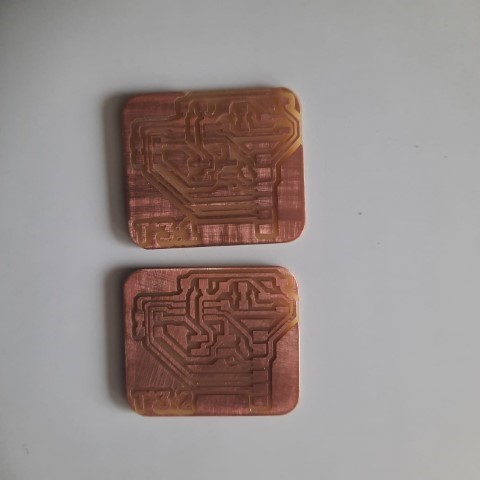
T^3.1 and T^3.2 is ready!
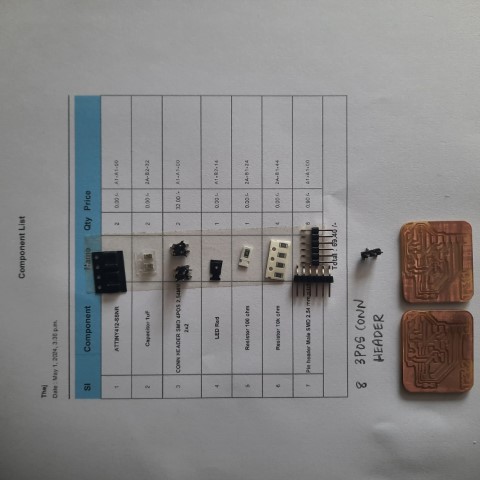
Components
So I requested for all components on FabLab Inventory Website and acquired them.
Soldering
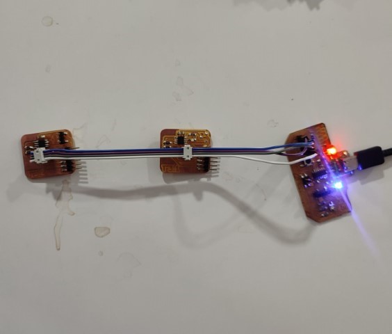
Here's the result:
Programming
I wanted to check if both the slave boards work well.
    #define LED_PIN 4

    void setup() {
        pinMode(LED_PIN, OUTPUT); // Set pin 4 as output
    }

    void loop() {
        digitalWrite(LED_PIN, HIGH); // Turn on the LED
        delay(1000); // Wait for 1 second
        digitalWrite(LED_PIN, LOW); // Turn off the LED
        delay(1000); // Wait for 1 second
    }
Slave 1 works alright.
    int servo = 4;

    int angle;
    int pwm;

    void setup()
    {
        pinMode(servo, OUTPUT);
    }

    void loop ()
    {
        for (angle = 0; angle <= 140; angle += 5)  {
        servoPulse(servo, angle);  }
        for (angle = 140; angle >= 0; angle -= 5)  {
        servoPulse(servo, angle);  }
    }

    void servoPulse (int servo, int angle)
    {
        pwm = (angle*11) + 500;      // Convert angle to microseconds
        digitalWrite(servo, HIGH);
        delayMicroseconds(pwm);
        digitalWrite(servo, LOW);
        delay(50);                   // Refresh cycle of servo
    }
It showed error first, UPDI wasn't getting intialised. Upon debugging, it was found that I had the inverted the chip. So I resoldered it correctly. And it worked!
Now, it's time to do the I2C Master-Slave communication
Master code. I chose my master board as T_CUBINO, it is my SAMD11 development board I designed during week 8.
    #include < Wire.h >

        #define SLAVE1_ADDRESS 0x10
        #define SLAVE2_ADDRESS 0x11
        #define BUTTON_PIN 2

        bool buttonState = false;
        bool lastButtonState = false;
        bool ledState = false;

        void setup() {
            Wire.begin();
            pinMode(BUTTON_PIN, INPUT_PULLUP);
        }

        void loop() {
            // Read the button state
            buttonState = digitalRead(BUTTON_PIN);

            // If button state has changed
            if (buttonState != lastButtonState) {
            // If button is pressed
            if (buttonState == LOW) {
                // Toggle LED state
                ledState = !ledState;

                // Send command to slaves based on LED state
                if (ledState) {
                Wire.beginTransmission(SLAVE1_ADDRESS);
                Wire.write(1); // Turn on LED
                Wire.endTransmission();
                } else {
                Wire.beginTransmission(SLAVE2_ADDRESS);
                Wire.write(1); // Rotate servo
                Wire.endTransmission();
                }
            }
            delay(50); // Debounce delay
            }

            lastButtonState = buttonState;
        }
T^3.1 Slave code for LED
    #include < Wire.h >
        #define LED_PIN 4

        void setup() {
            Wire.begin(0x10); // Address for Slave 1
            Wire.onReceive(receiveEvent);
            pinMode(LED_PIN, OUTPUT);
        }

        void loop() {
            delay(100); // Keep the loop running
        }

        void receiveEvent(int bytes) {
            int command = Wire.read();
            if (command == 1) {
            // Turn on LED
            digitalWrite(LED_PIN, HIGH);
            delay(500); // Blink duration
            digitalWrite(LED_PIN, LOW);
            }
        }
T^3.2 Slave code for working the servo
        #include < Wire.h >

            #define SERVO_PIN 4

            void setup() {
                Wire.begin(0x11); // Address for Slave 2
                Wire.onReceive(receiveEvent);
                pinMode(SERVO_PIN, OUTPUT);
            }

            void loop() {
                delay(100); // Keep the loop running
            }

            void receiveEvent(int bytes) {
                int command = Wire.read();
                if (command == 1) {
                // Rotate the servo to 90 degrees (adjust PWM value as needed)
                pwmServo(90);
                delay(1000); // Delay to allow servo to reach position
                }
            }

            void pwmServo(int angle) {
                int pwm = (angle * 11) + 500; // Convert angle to PWM signal (adjust as needed)
                digitalWrite(SERVO_PIN, HIGH);
                delayMicroseconds(pwm);
                digitalWrite(SERVO_PIN, LOW);
                delay(20); // Refresh cycle of servo (adjust as needed)
            }
This not functioning like I expected it to. LED and servo motor should turn on alternatively as I press the button. It only worked once so I will have to debug it.
I modified the code I found in the documentation of Luis Diazfaes
This code works without button and through the iteration of i from 1 to 4. (In the code, 0 to 3)When i=1, the LED of the master board blinks one time.
When i=2, the LED of the master board blinks two times & LED of slave board turns on.
When i=3, the LED of the master board blinks three times & servo of next slave board turns on.
When i=4, the LED of the master board blinks four times
This loop repeats.
Master code for T_CUBINO
    #include < Wire.h >

        int i = 0;
        int j = 0;

        int led = 1;

        void setup() {
            Serial.begin(9600);
            Wire.begin();

            pinMode(led, OUTPUT); // led
        }

        void loop()
        {

            for (i = 0; i <= 3; i++) { // 0,1,2,3

            Wire.beginTransmission(8); //slave number 8
            if ( i == 1) {
                Wire.write(1);
                Serial.println("1");
            } else {
                Wire.write(0);
                Serial.println("0");
            }
            Wire.endTransmission();

            Wire.beginTransmission(9); //slave number 9
            if ( i == 2) {
                Wire.write(1);
                Serial.println("1");
            } else {
                Wire.write(0);
                Serial.println("0");
            }
            Wire.endTransmission();

            for (j = 0; j <= i; j++) { // blink i times
                digitalWrite(led, HIGH);
                delay(200);
                digitalWrite(led, LOW);
                delay(200);
            }

            delay(1000);
            }

        }
T^3.1 code
    #include < Wire.h >
    #define led 4
    int d1=0;

    void setup() {
        pinMode(led, OUTPUT);
        Serial.begin(9600);
        Wire.begin(8); // change address
        Wire.onReceive(receiveEvent);
    }

    void loop() {
        if (d1 == 1) {
        digitalWrite(led, HIGH);
        } else {
        digitalWrite(led, LOW);
        }
        delay(500);
    }

    void receiveEvent(int howMany) {
        while (Wire.available()) {
        d1 = Wire.read();
        }
    }
T^3.2 code
    #include < Wire.h >
    int servo = 4;
    int d1=0;
    int angle;
    int pwm;

    void setup() {
        pinMode(servo, OUTPUT);
        Serial.begin(9600);
        Wire.begin(9); // change address
        Wire.onReceive(receiveEvent);
    }

    void loop() {
        if (d1 == 1) {
        for (angle = 0; angle <= 140; angle += 10)  {
            servoPulse(servo, angle);  }
        for (angle = 140; angle >= 0; angle -= 10)  {
            servoPulse(servo, angle);  }
        } else {

        }
        delay(500);
    }

    void receiveEvent(int howMany) {
        while (Wire.available()) {
        d1 = Wire.read();
        }
    }

    void servoPulse (int servo, int angle)
    {
        pwm = (angle*11) + 500;      // Convert angle to microseconds
        digitalWrite(servo, HIGH);
        delayMicroseconds(pwm);
        digitalWrite(servo, LOW);
        delay(50);                   // Refresh cycle of servo
    }
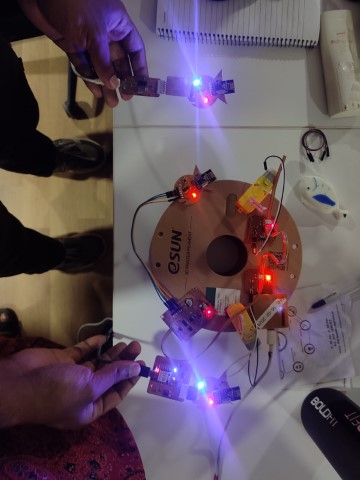
It works! Success!
Group Assignment
Click here: Send a message between two projects