Output Devices
The assignments for this week:
- Individual assignment:
- add an output device to a microcontroller board you've designed, and program it to do something
- Group assignment :
- measure the power consumption of an output device
About Output devices
Output devices are the important part of any electronic device. Output devices can be used in different applications to help users interact with digital information in a more meaningful way.An output device is a hardware component that translates processed data into a form that can be understood byus or used by other devices. In this context, output is the final result that users can see, hear, or physically interact with. Outputs can be viewed on a screen, printed, played as audio, or sent to another device.
How Output Devices Work
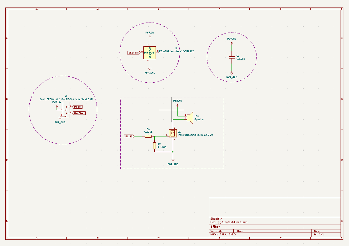
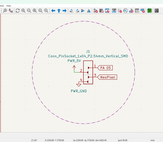
The exact way a specific output device works will vary depending on the type of output it produces, but the general process works something like this:I planned to add two output devices, a speaker and a neopixel. The components needed for this:
- Gate (G): The gate terminal controls the flow of current between the source and drain terminals. By applying a voltage to the gate terminal, you can modulate the conductivity of the channel between the source and drain, thereby controlling the current flow.
- Drain (D): The drain terminal is where the majority carriers exit the device. It is the terminal where the output signal is usually taken.
- Source (S): The source terminal is where the majority carriers enter the device. It's typically connected to the more negative side of the circuit or ground.
Using a capacitor can also help improve the overall performance of the NeoPixels by reducing noise in the power supply and minimizing voltage fluctuations. This can lead to smoother color transitions and more reliable operation.
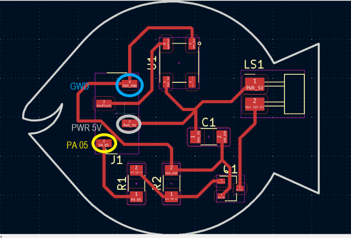
In this schematic:
This is how it works:
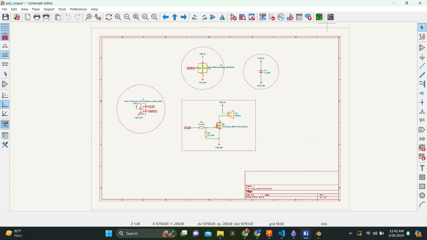
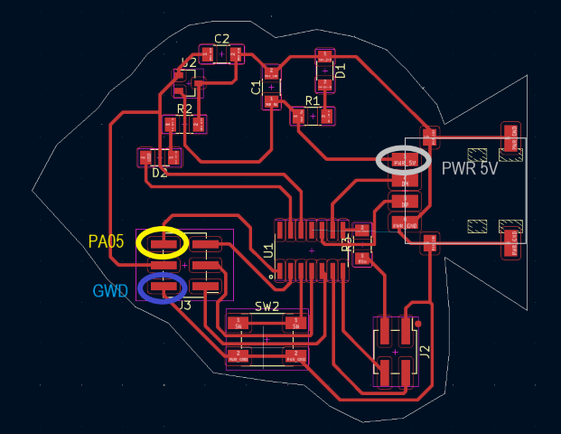
KiCad Editor
Once it is imported to KiCad editor, the components need to be arranged such that the connections don't cross each other.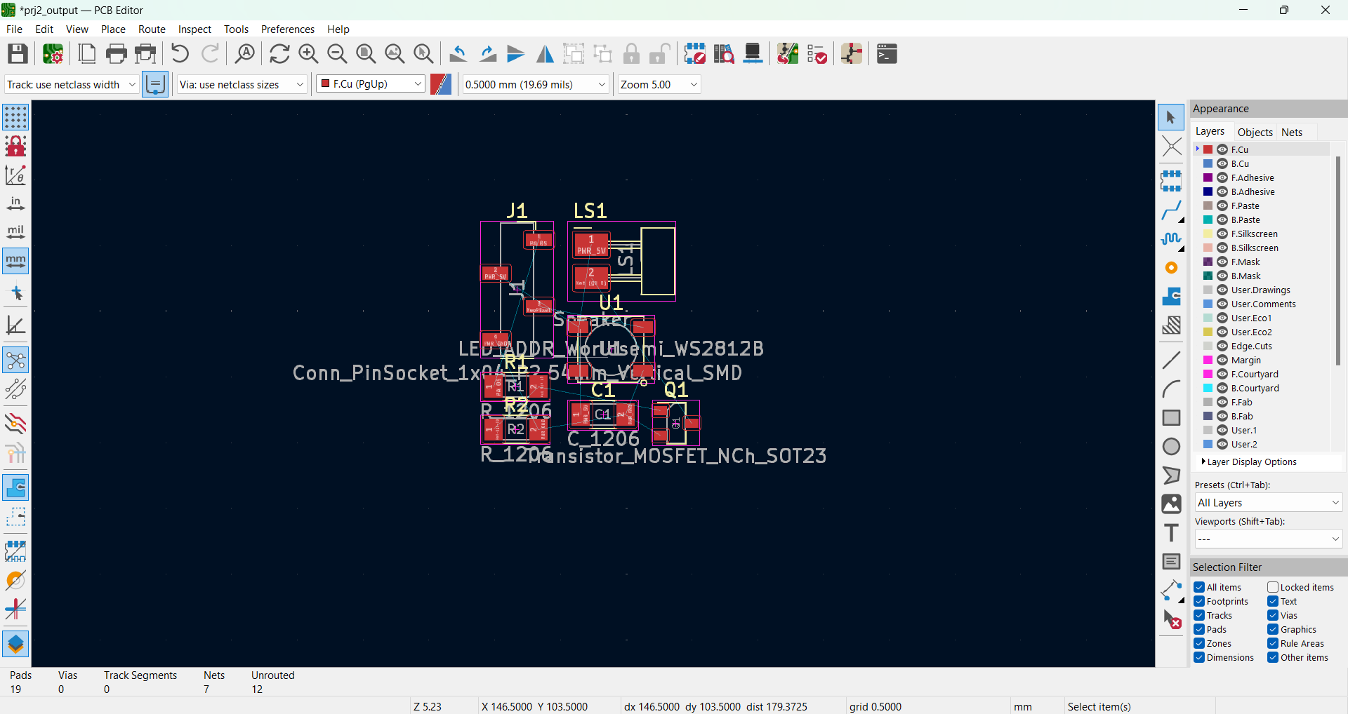
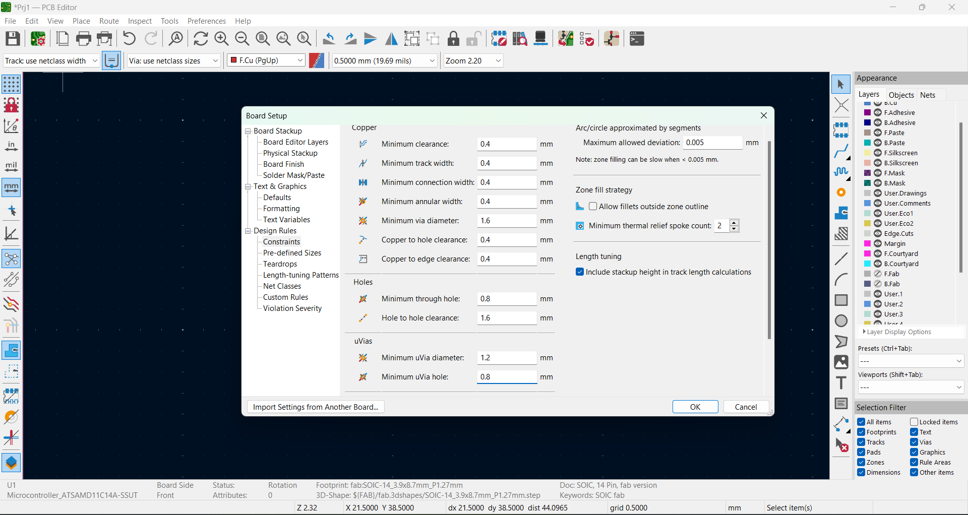
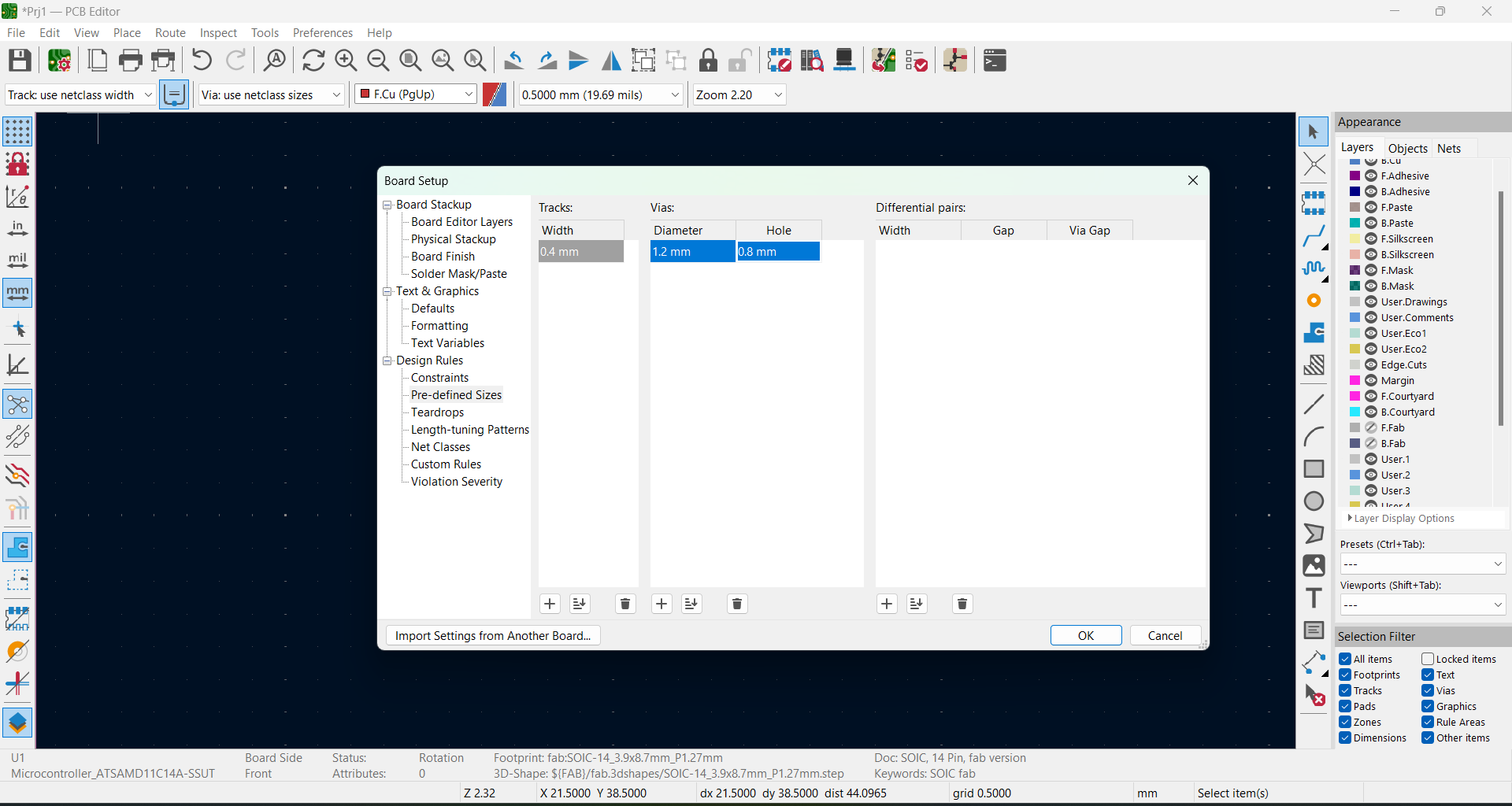
We need to edit the settings for routing.
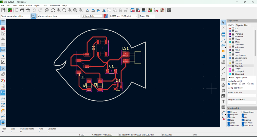
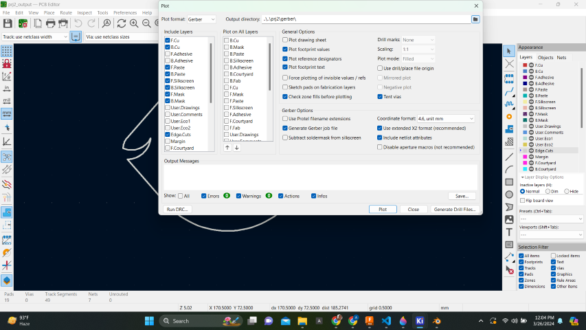
Once, it is arranged, we can get the fabrication outputs from here:
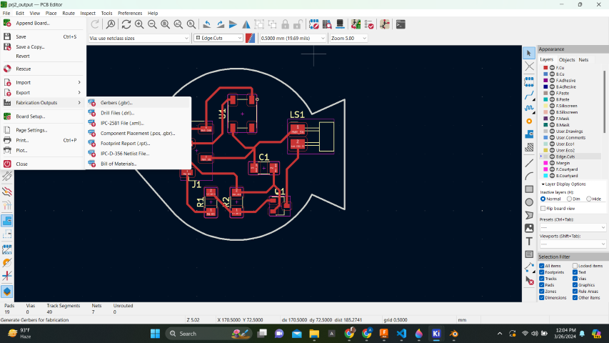
The path to save the traces are here:
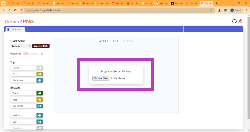
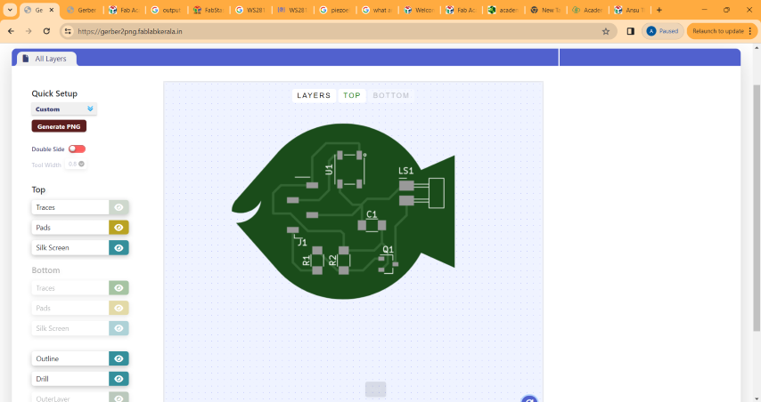
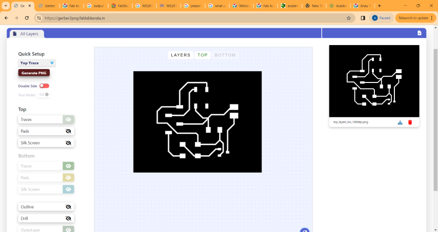
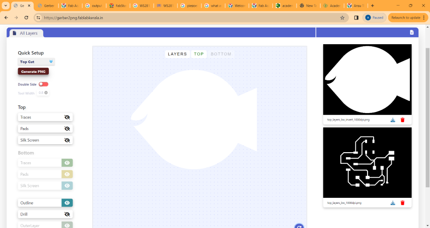
We can convert the gerber files to png from this site: Gerber Viewer Drag and drop the files and generate the top trace and top cut as shown:
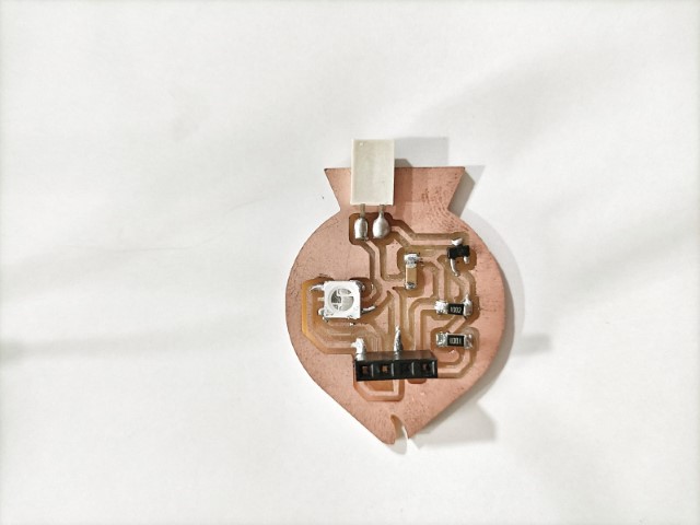
PCB milling
Using the traces mentioned above, I milled the PCB in the Modela using the same procedures mentioned in Week 4 - Electronics Production weekSoldering
I collected the required components from the fablab inventory.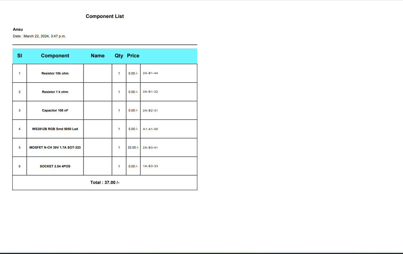
Here again, soldering was done using the same procedures followed in Week 4 - Electronics Production week
Connecting the two boards
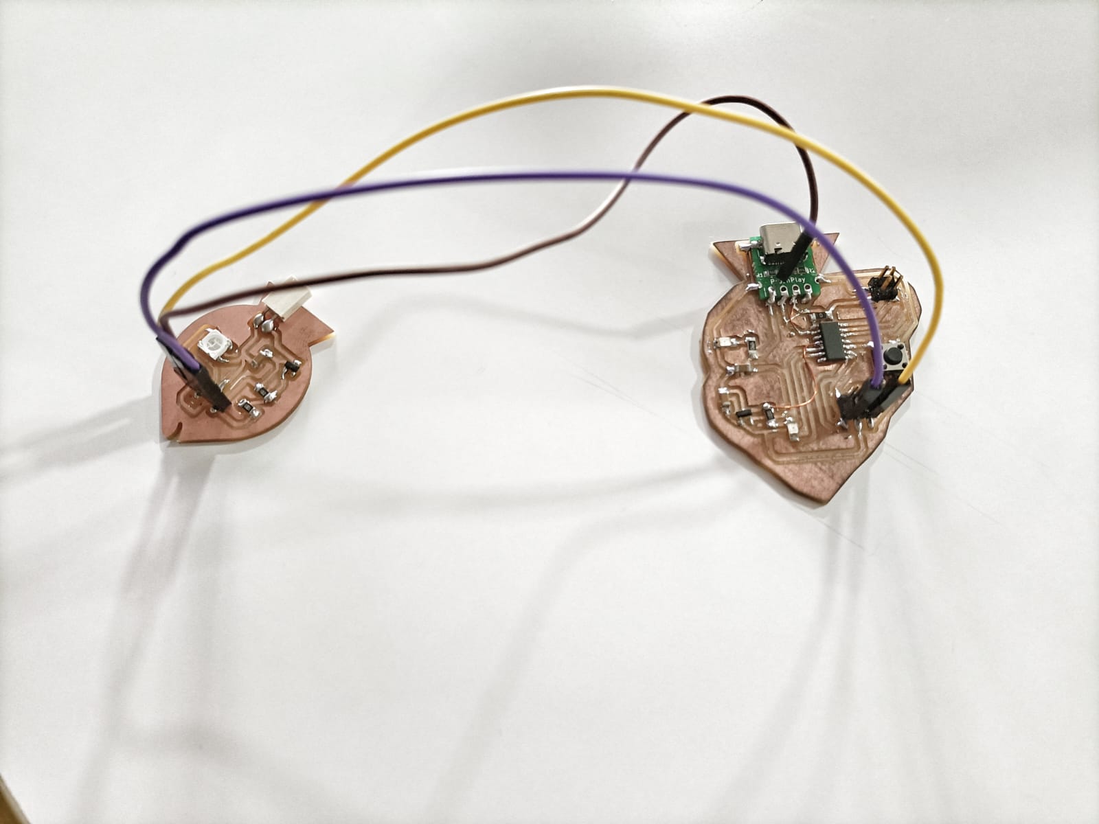
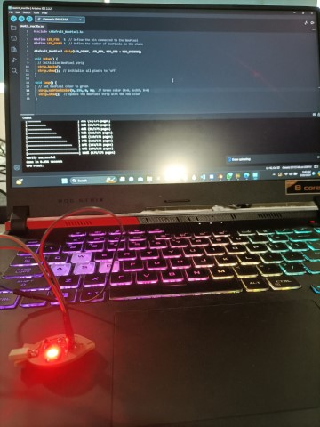
Neopixel as an Output device
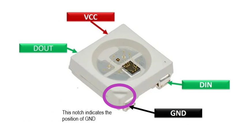
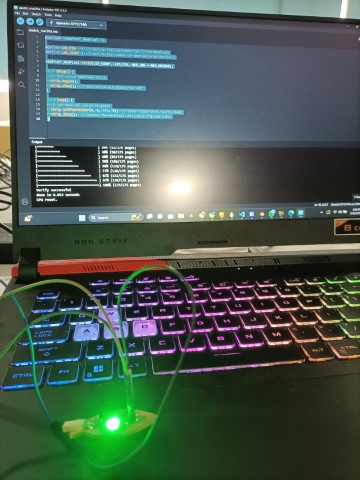
NeoPixels are special LEDs - they're not just one light but three! Each NeoPixel contains tiny red, green, and blue lights all in one package.To light up the Neopixel
      #include < Adafruit_NeoPixel.h>

        #define LED_PIN   5  // Define the pin connected to the NeoPixel
        #define LED_COUNT 1  // Define the number of NeoPixels in the chain

        Adafruit_NeoPixel strip(LED_COUNT, LED_PIN, NEO_GRB + NEO_KHZ800);

        void setup() {
          // Initialize NeoPixel strip
          strip.begin();
          strip.show();  // Initialize all pixels to 'off'
        }

        void loop() {
          // Set NeoPixel color to green
          strip.setPixelColor(0, 0, 255, 0);  // Green color (R=0, G=255, B=0)
          strip.show();  // Update the NeoPixel strip with the new color
        }
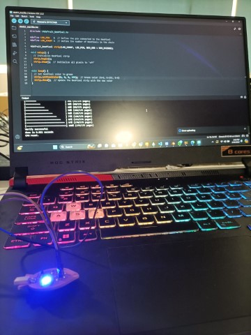
Changing this command, I got red colour. strip.setPixelColor(0, 255, 0, 0);
Changing this command again, I got blue colour. strip.setPixelColor(0, 0, 0, 255);
To colour cycle the neopixel
#include < Adafruit_NeoPixel.h>

  #define LED_PIN     5   // Define the pin connected to the NeoPixel
  #define LED_COUNT   1   // Define the number of NeoPixels in the chain

  Adafruit_NeoPixel strip(LED_COUNT, LED_PIN, NEO_GRB + NEO_KHZ800);

  void setup() {
    // Initialize NeoPixel strip
    strip.begin();
    strip.show();  // Initialize all pixels to 'off'
  }

  void loop() {
    colorCycle(10);  // Speed of color cycling (adjust as needed)
  }

  // Function to cycle through colors
  void colorCycle(uint8_t wait) {
    uint16_t i;

    for(i = 0; i < 256; i++) {
      // Set NeoPixel color
      strip.setPixelColor(0, Wheel((i) & 255));
      strip.show();
      delay(wait);  // Wait between colors
    }
  }

  // Input a value 0 to 255 to get a color value
  // The colors are a transition r - g - b - back to r
  uint32_t Wheel(byte WheelPos) {
    if(WheelPos < 85) {
      return strip.Color(WheelPos * 3, 255 - WheelPos * 3, 0);
    } else if(WheelPos < 170) {
      WheelPos -= 85;
      return strip.Color(255 - WheelPos * 3, 0, WheelPos * 3);
    } else {
      WheelPos -= 170;
      return strip.Color(0, WheelPos * 3, 255 - WheelPos * 3);
    }
  }
Speaker as an output device
Since I was planning to use a speaker ,it is required to use a trasistor. I used MOSFET (Metal-Oxide-Semiconductor Field-Effect Transistor). It is a type of transistor commonly used in electronic circuits for switching and amplifying electronic signals. When using a MOSFET with a speaker, it's typically employed as a switch to control the flow of current through the speaker.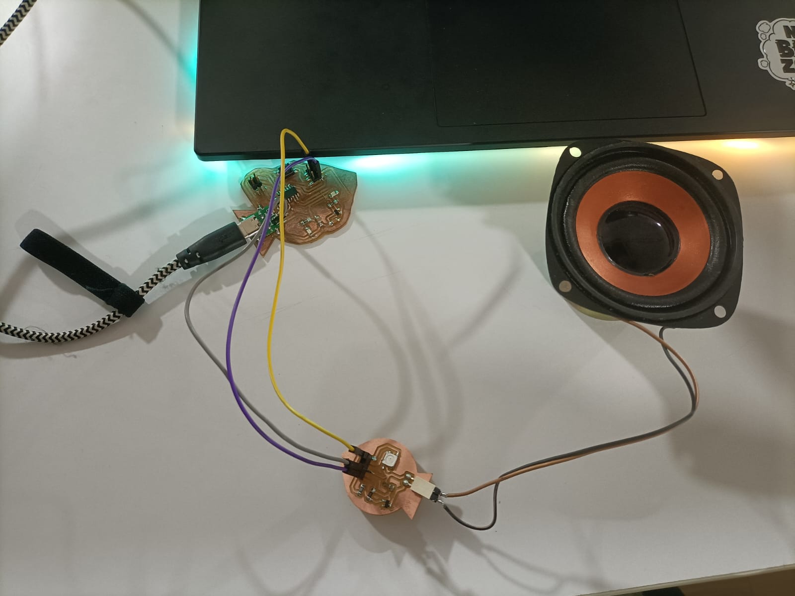
This code of the nursery rhythm, Twinkle Twinkle.
      #define led 2  // led pin

      #define speakerPin  5

      int length = 28;  // the number of notes
      char notes[] = "CCGGAAG FFEEDDC GGFFEED GGFFEED CCGGAAG FFEEDDC "; // Twinkle, Twinkle, Little Star
      int beats[] = { 4, 4, 4, 4, 4, 4, 2, 4, 4, 4, 4, 4, 4, 2, 4, 4, 4, 4, 4, 4, 4, 4, 4, 4, 4, 4, 2 }; // Corresponding beats
      int tempo = 150;


      void playTone(int tone, int duration) {
        for (long i = 0; i < duration * 1000L; i += tone * 2) {
          digitalWrite(speakerPin, HIGH);
          delayMicroseconds(tone);
          digitalWrite(speakerPin, LOW);
          delayMicroseconds(tone);
        }
      }
      void playNote(char note, int duration) {
        char names[] = { 'C', 'D', 'E', 'F', 'G', 'A', 'B', 'c', 'd', 'e', 'f', 'g', 'a', 'b', 'x', 'y' };
        int tones[] = { 1915, 1700, 1519, 1432, 1275, 1136, 1014, 956, 834, 765, 593, 468, 346, 224, 655, 715 };
        int SPEE = 5;  // play the tone corresponding to the note name
        for (int i = 0; i < 17; i++) {
          if (names[i] == note) {
            int newduration = duration / SPEE;
            playTone(tones[i], newduration);
          }
        }
      }

      void setup() {

        pinMode(speakerPin, OUTPUT);  //buzzer
        pinMode(led, OUTPUT);
        digitalWrite(led, HIGH);
        delay(1000);
        digitalWrite(led, LOW);
      }
      void loop() {
         for (int i = 0; i < length; i++) {
          if (notes[i] == ' ') {
            delay(beats[i] * tempo);  // rest
          } else {
            playNote(notes[i], beats[i] * tempo);
          }
          // pause between notes
          delay(tempo);
        }
        delay(100);
      }
Problems Encountered
    #define led 2  // led pin

    #define speakerPin  5

    int length = 28;  // the number of notes
    char notes[] = "GGAGcB GGAGdc GGxecBA yyecdc";
    int beats[] = { 2, 2, 8, 8, 8, 16, 1, 2, 2, 8, 8, 8, 16, 1, 2, 2, 8, 8, 8, 8, 16, 1, 2, 2, 8, 8, 8, 16 };
    int tempo = 150;


    void playTone(int tone, int duration) {
      for (long i = 0; i < duration * 1000L; i += tone * 2) {
        digitalWrite(speakerPin, HIGH);
        delayMicroseconds(tone);
        digitalWrite(speakerPin, LOW);
        delayMicroseconds(tone);
      }
    }
    void playNote(char note, int duration) {
      char names[] = { 'C', 'D', 'E', 'F', 'G', 'A', 'B', 'c', 'd', 'e', 'f', 'g', 'a', 'b', 'x', 'y' };
      int tones[] = { 1915, 1700, 1519, 1432, 1275, 1136, 1014, 956, 834, 765, 593, 468, 346, 224, 655, 715 };
      int SPEE = 5;  // play the tone corresponding to the note name
      for (int i = 0; i < 17; i++) {
        if (names[i] == note) {
          int newduration = duration / SPEE;
          playTone(tones[i], newduration);
        }
      }
    }

    void setup() {

      pinMode(speakerPin, OUTPUT);  //buzzer
      pinMode(led, OUTPUT);
      digitalWrite(led, HIGH);
      delay(1000);
      digitalWrite(led, LOW);
    }
    void loop() {
       for (int i = 0; i < length; i++) {
        if (notes[i] == ' ') {
          delay(beats[i] * tempo);  // rest
        } else {
          playNote(notes[i], beats[i] * tempo);
        }
        // pause between notes
        delay(tempo);
      }
      delay(100);
    }
It was our friend, Kalyani's birthday today and we had a surprise for her and we played the song.
Group assignment:
Power consumption of an output device
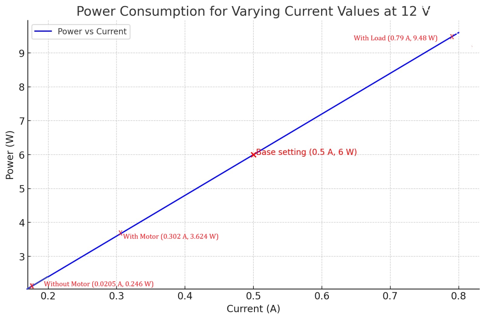
Power, measured in watts (W), is the rate at which energy is transferred or consumed in a circuit. It is a key factor in determining the performance and efficiency of electronic devices. Power can be calculated using two different formulas: Power (P)=Voltage (V)×Current (I) This formula states that power (measured in watts) is the product of voltage (measured in volts) and current (measured in amperes). or P = I^2 * R (using current and resistance).
By understanding the relationship between power, voltage, current, and resistance, we can optimize circuit designs and select components that meet specific power requirements. It is important to note that power dissipation and energy efficiency are crucial considerations in electronic systems, as excessive power consumption can lead to inefficiencies, heat generation, and reduced lifespan of components.
To measure the power consumption of an output device,we need to measure both the current and the voltage, since direct measurement of power is not straightforward. A multimeter can be used to measure both voltage and current. For determining the power consumption of an output device:
12V×2A=24W
This indicates that the motor consumes 24 watts of power.
Design files
KiCad for schematic with Samd11Border for the pcb
Program- Neopixel_green colour
Program-Neopixel_colour cycling