
Electronics Design
The assignments for this week:
- Group assignment :
- use the test equipment in your lab to observe the operation of a microcontroller circuit board
- Individual assignment:
- use an EDA tool to design a development board to interact and communicate with an embedded microcontroller, produce it, and test it
- extra credit:try another design workflow
- extra credit:design a case for it
- extra credit: simulate its operation
Group assignment:
Exploring Electronic world
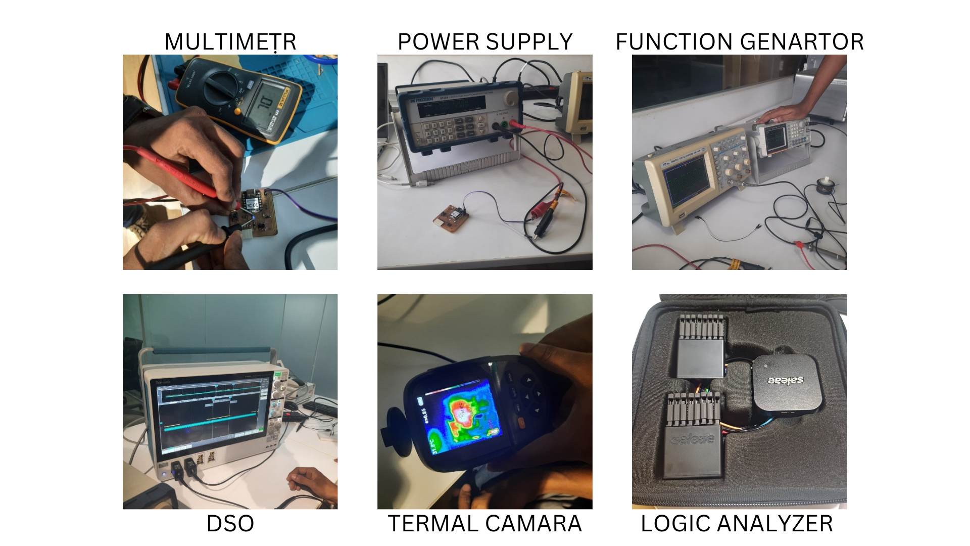
This week is something quite new for me. If you are like me, who uses electronic gadgets comfortably and have no idea of how it works, come join me....lets explore this new world together.The first day of the week, our instructior, Saheen started by introducing us to different test machines.In the world of electronics, there are several indispensable tools that every beginner should acquaint themselves with. Whether you're just starting out on your electronic journey or looking to deepen your understanding, getting to know tools like multimeters, logic analyzers, clamp meters, and oscilloscopes is crucial. Let's delve into each one, breaking down their purpose and functionality.
Multimeter:
Think of a multimeter as your all-in-one tool for measuring various electrical parameters. It's like having a Swiss Army knife in your toolbox. With a multimeter, you can measure voltage, current, resistance, and sometimes even more. It's perfect for troubleshooting circuits, checking battery voltages, and testing components like resistors and diodes. Multimeters come in analog and digital variants, with digital ones being more common due to their ease of use and accuracy.
DC Lab Bench Power Supply:
Function Generator: A function generator is used to generate various types of electrical waveforms.
Logic Analyzer:
In the digital realm of electronics, understanding how signals behave is crucial. This is where a logic analyzer comes into play. Imagine it as a detective that helps you unravel the mysteries of digital signals. A logic analyzer captures and analyzes digital signals, allowing you to visualize their behavior over time. It's invaluable for debugging digital circuits, decoding communication protocols and ensuring that your digital systems are working as intended.
Clamp Meter:
Measuring current in a circuit used to be a tricky affair, requiring you to break the circuit and insert a meter in series. Enter the clamp meter, a game-changer for current measurement. Its unique design allows you to measure current without breaking the circuit. Simply clamp it around a wire, and voila! You can measure AC or DC current flowing through that wire. Clamp meters are indispensable for electricians, technicians, and hobbyists working with electrical systems.
Oscilloscope:
Ever wanted to see how electrical signals look like in real-time? That's where an oscilloscope comes in handy. Think of it as a window into the world of electrical signals. An oscilloscope displays voltage signals as waveforms on a screen, allowing you to visualize their amplitude, frequency, and shape. It's like watching the heartbeat of your circuit in action. Oscilloscopes are essential for troubleshooting circuits, analyzing waveforms, and designing electronic circuits.
Whether you're measuring voltages with a multimeter, decoding digital signals with a logic analyzer, measuring current with a clamp meter, or visualizing waveforms with an oscilloscope, each tool plays a vital role in understanding and working with electronics.
Ohm's Law
Ohm's Law is a fundamental principle in electronics that describes the relationship between voltage, current, and resistance in an electrical circuit.Voltage (V): Voltage is the measure of electrical potential difference between two points in a circuit. It's like the "push" that moves electrical charge through a circuit. Voltage is measured in volts (V).
Current (I): Current is the flow of electrical charge through a conductor. It's like the "flow" of water through a pipe. Current is measured in amperes (amps, A).
Resistance (R): Resistance is the property of a material that opposes the flow of electrical current. It's like the "narrowness" of a pipe, which makes it harder for water to flow through. Resistance is measured in ohms (Ω).
To understand this better, Saheen showed us an image:

Ohm's Law tells us that the voltage across a component in a circuit (V) is equal to the product of the current flowing through the component (I) and the resistance of the component (R). In other words:
- If you increase the voltage across a component, the current through it will also increase, assuming the resistance remains constant.
- If you increase the resistance of a component, the current through it will decrease, assuming the voltage remains constant.
- If you increase the resistance of a component, the voltage drop across it will increase, assuming the current remains constant.
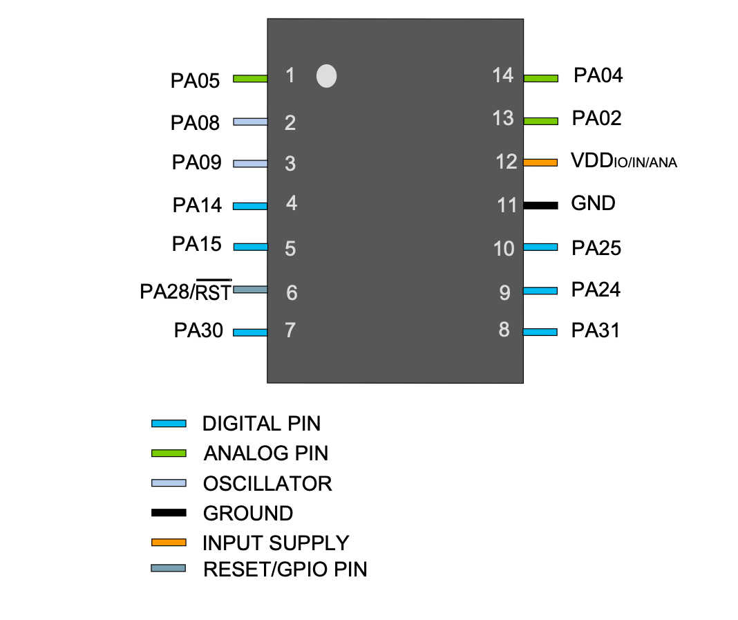
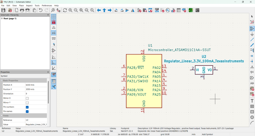
- VDD: Supply voltage.
- GND: Ground.
- Digital pins: PA02, PA04, PA05, PA08, PA09, PA14, PA15, PA31.
- Analog pins: PA02, PA04, PA05, PA14, PA15.
- USB pins: PA24, PA25.
- After installing the software, I stored the library in 'Documents'.
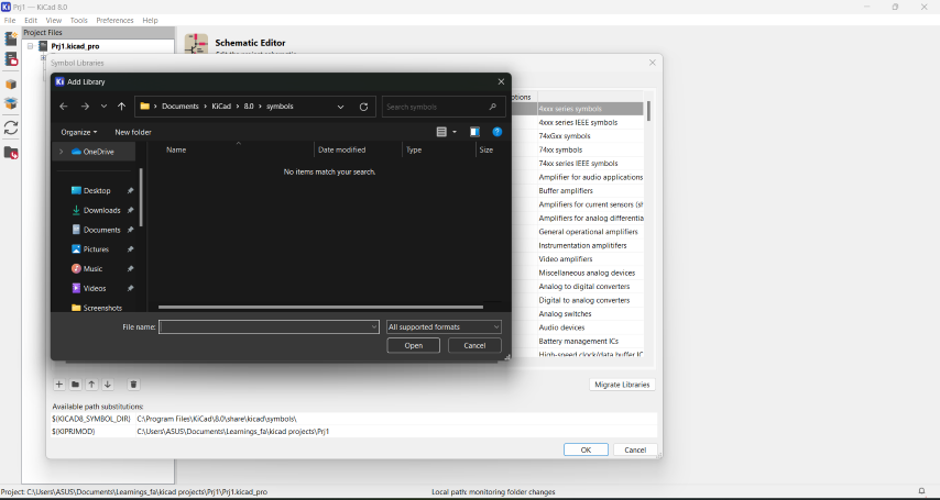
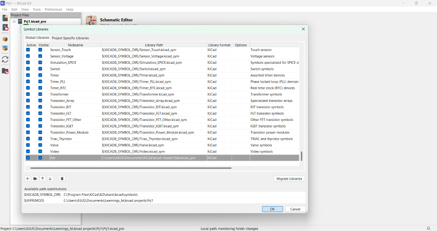
- It is required to import two libraries. For this, after opening KiCad, go to 'Preferences' , then 'manage symbol library' and follow the path shown below:
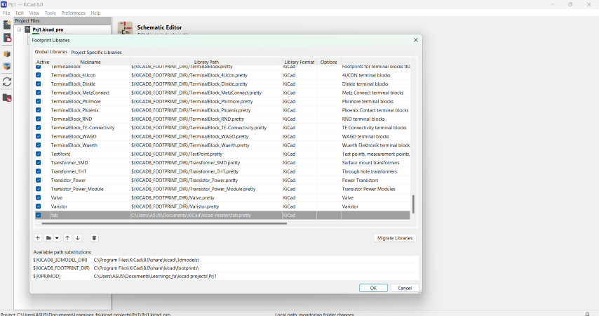
- Next, I imported the 'Footprint library' from the following path:
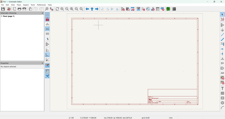
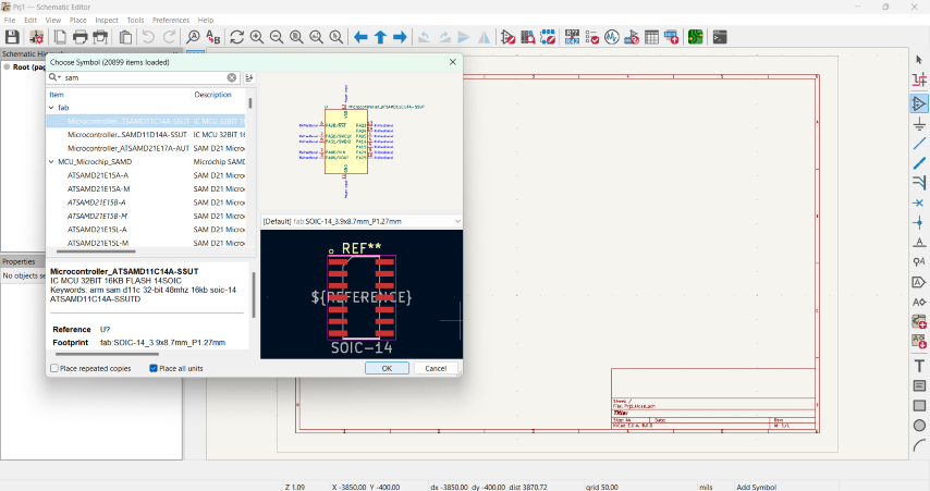
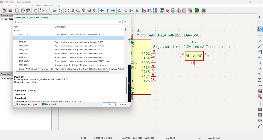
- Now, to start the schematic editor. Add, the SAMD11C, from the library under 'fab item'.
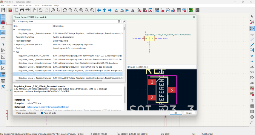
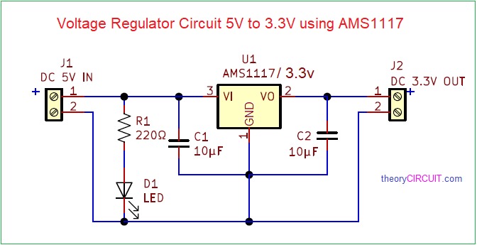
- Since we are going to use the SAMD11 ,a voltage regulator is required when you connect to the computer usb port that is around 5.5V.Voltage regulator circuit is used to provide a stable and regulated voltage supply to the microcontroller and its associated components. This ensures that the microcontroller operates reliably within its specified voltage range(1.62V to 3.63V), regardless of fluctuations or variations in the input voltage. In a voltage regulator,
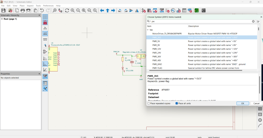
- Connect the input pin (Vin) of the voltage regulator to your power source. Ensure that the voltage supplied by the source is higher than the desired output voltage and within the maximum input voltage rating of the regulator.Here, we have used a AMS1117
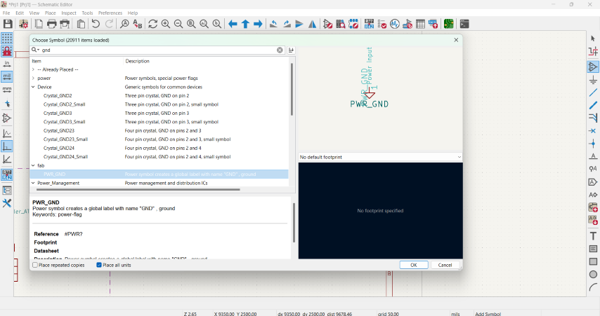
- Connect the ground (GND) pin of the voltage regulator to the ground of your power source.
- Connect the output pin (Vout) of the voltage regulator to the VCC pin of the SAMD11 microcontroller.
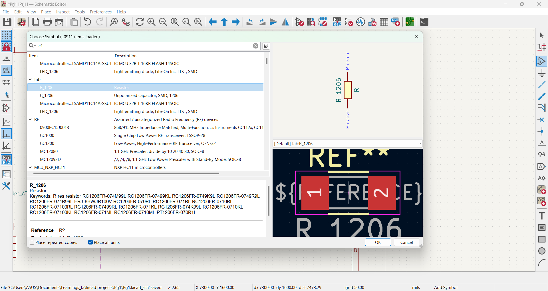
- Place a ceramic capacitor (typically in the range of 0.1μF to 1μF) between the input pin (Vin) and ground (GND) of the voltage regulator. This capacitor helps to stabilize the input voltage and reduce noise.
- Place another ceramic capacitor (similar range as above) between the output pin (Vout) and ground (GND) of the voltage regulator. This capacitor helps to stabilize the output voltage and reduce noise.
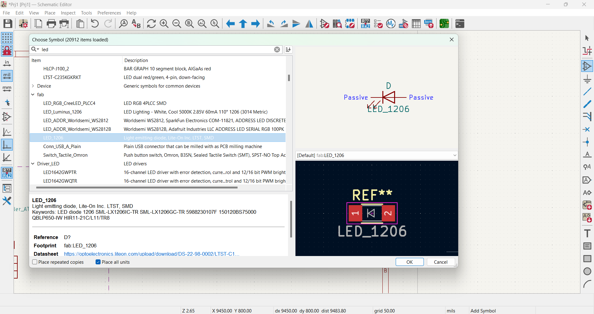
- Adding an LED to a voltage regulator board serves as a visual indicator to confirm that the board is receiving power and the regulator is functioning properly. When the board is powered, the LED lights up, providing a quick visual cue that everything is operational.
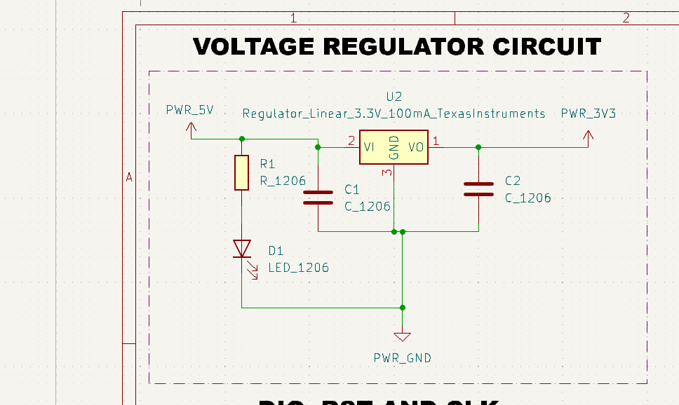
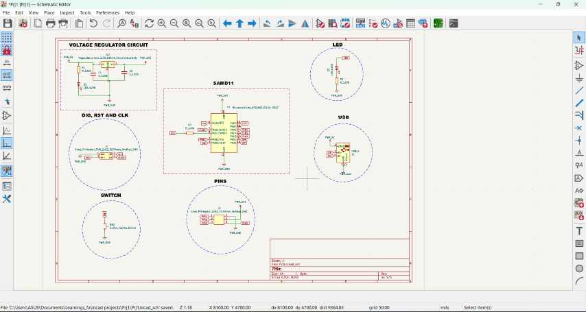
- Here is the voltage regulator circuit and the schematic diagram in KiCad
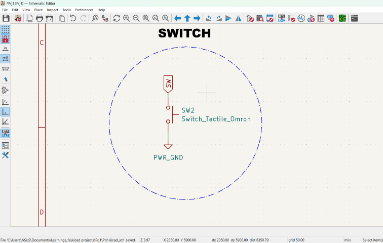
- Adding a switch.
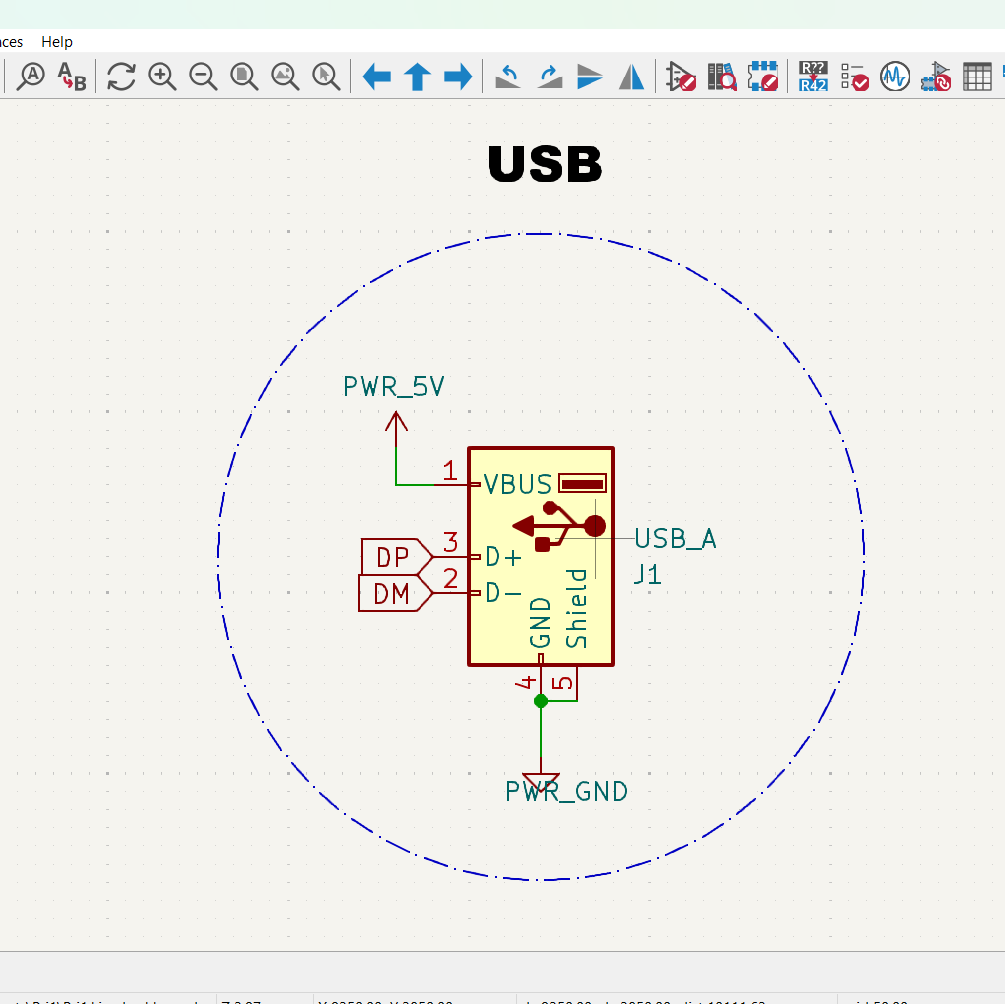
- Adding the USB port.
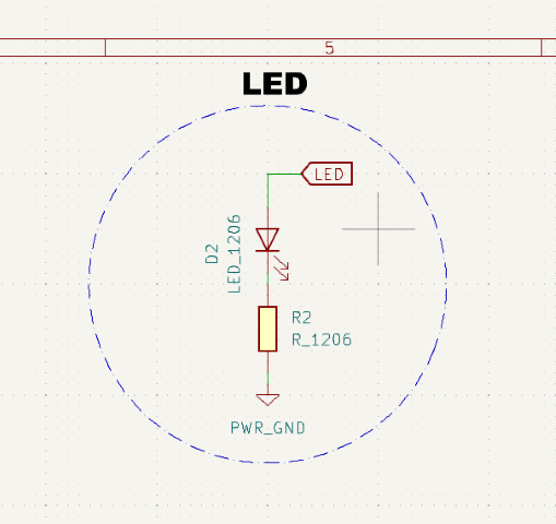
- Adding a LED.
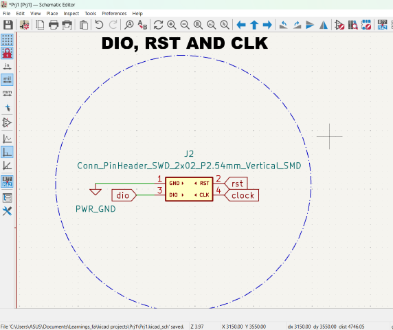
- Adding the dio, rst and clk.
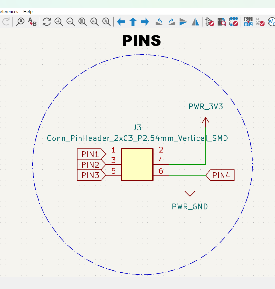
- Adding pins.
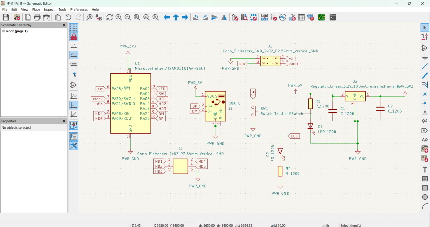
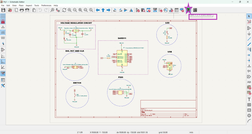
- Here is the completed circuit.
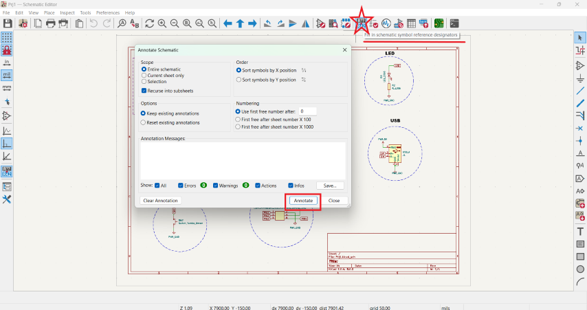
- To annotate the schematic symbols.
- Run the Design Rule Check (DRC) to ensure that the PCB layout meets manufacturing requirements and constraints.
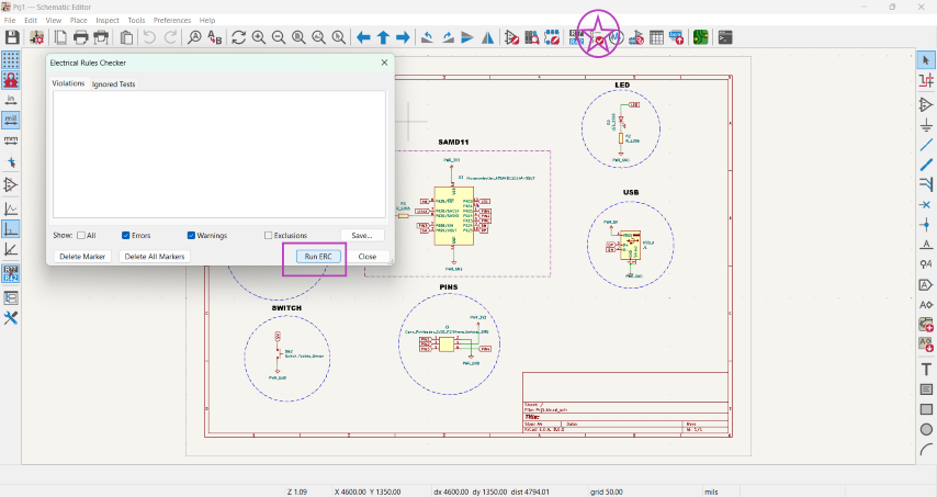
- Run the Electrical Rule Check (ERC) to verify the electrical connectivity and integrity of the circuit.
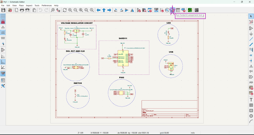
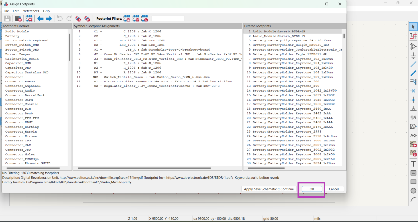
- Run the footprint assignment test to ensure all the symbols have footprints.
- To open the pcb in the editor.
SAMD11C
The SAMD11C14A is a low-power microcontroller using the 32-bit ARM Cortex-M0+ processor with 16KB Flash and 4KB of SRAM.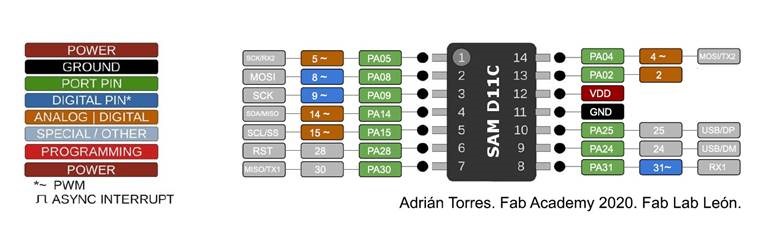
.png)
.png)
.png)
Using KiCad
KiCad is a free software suite for electronic design automation (EDA). It facilitates the design and simulation of electronic hardware for PCB manufacturing. We can install KiCad from www.kicad.org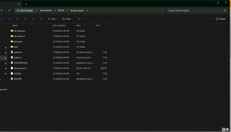
.png)
KiCad Editor
Once it is imported to KiCad editor, the components need to be arranged such that the connections don't cross each other.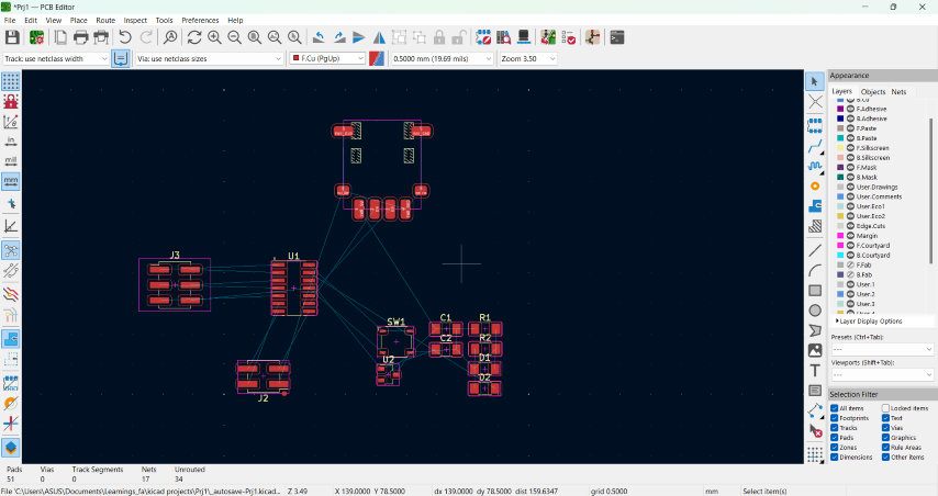
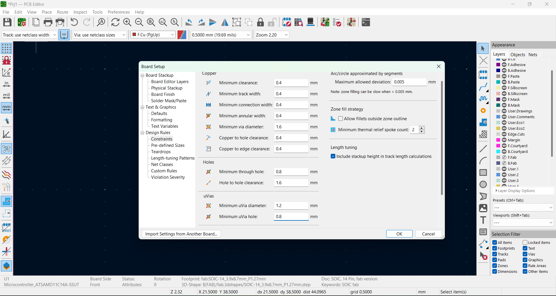
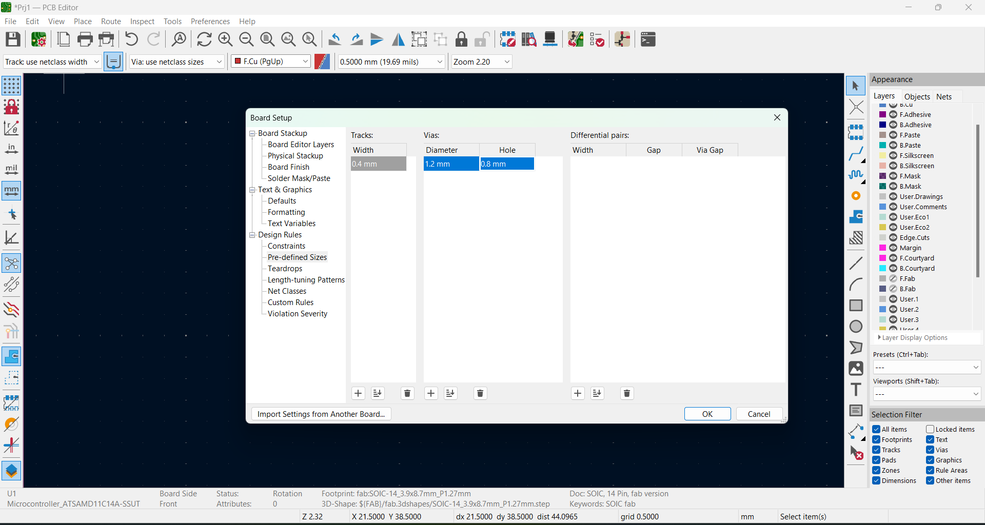
We need to edit the settings for routing.
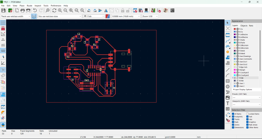
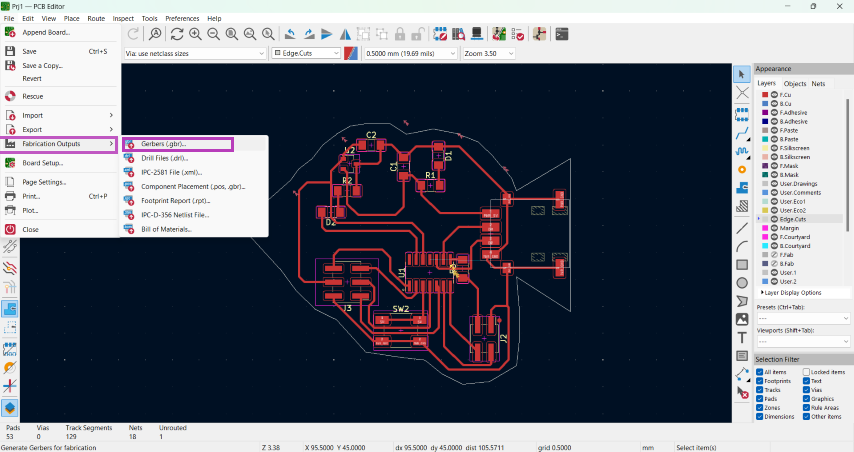
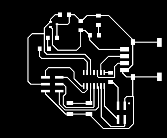
Once, it is arranged, we can get the fabrication outputs from here:
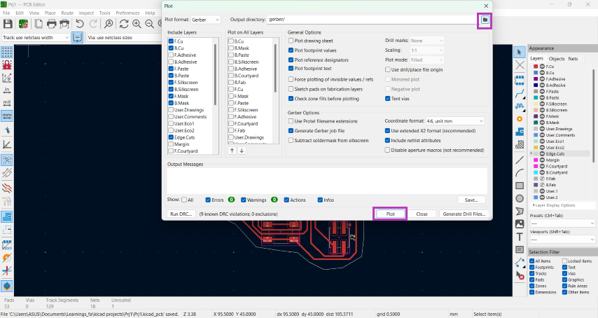
The path to save the traces are here:
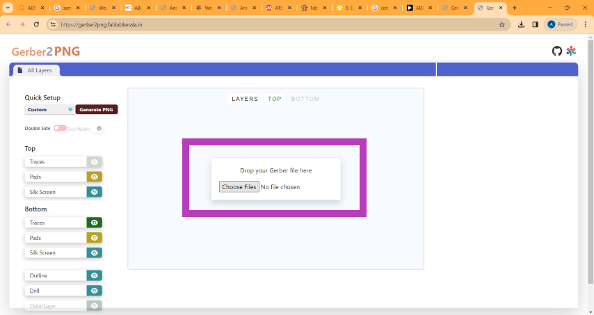
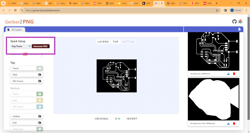
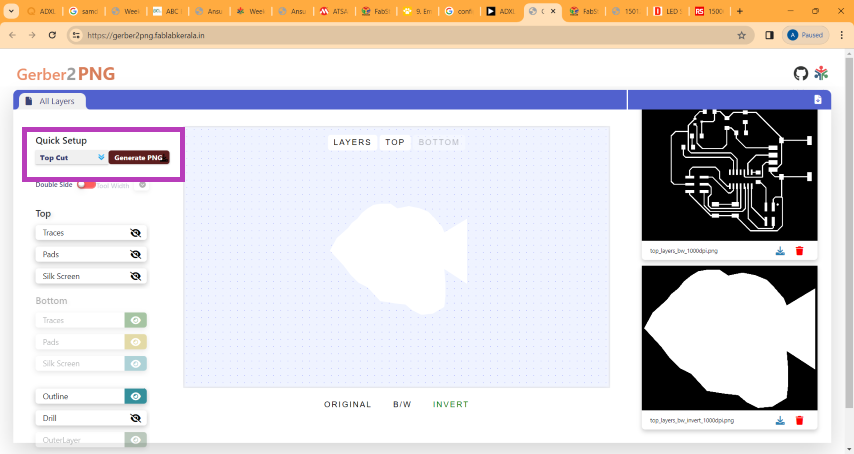
We can convert the gerber files to png from this site: Gerber Viewer Drag and drop the files and generate the top trace and top cut as shown:
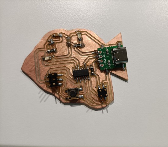
PCB milling
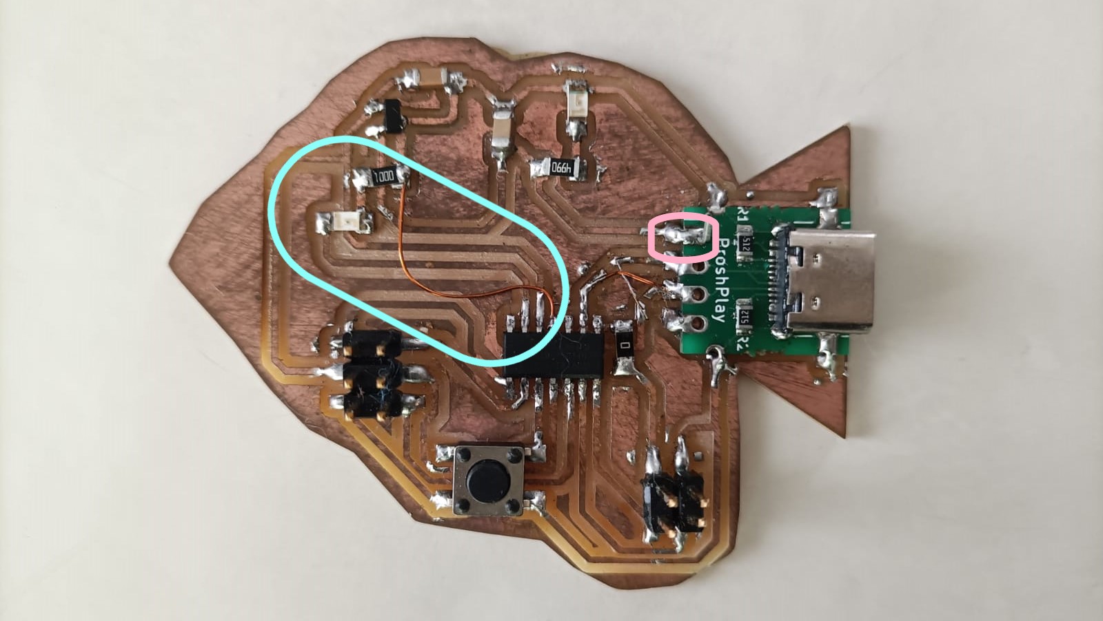
Using the traces mentioned above, I milled the PCB in the Modela using the same procedures mentioned in Week 4 - Electronics Production weekSoldering
I collected the required components from the fablab inventory.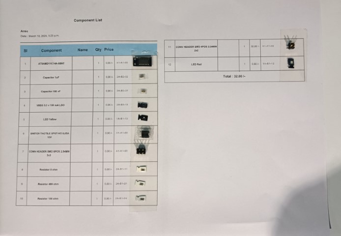
Here again, soldering was done using the same procedures followed in Week 4 - Electronics Production week
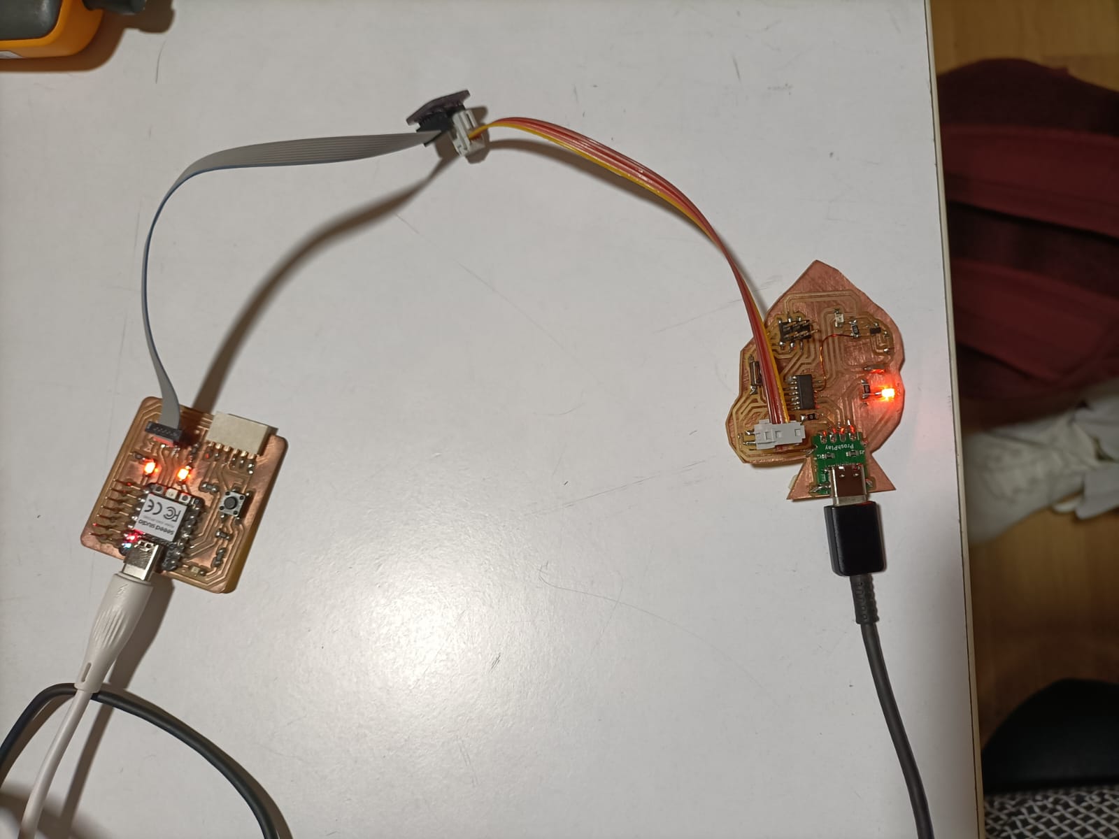
Programming the board
We should update the firmware on the electronics board to enable it to function as a programmer. For this, the documentation from Quentorres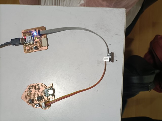
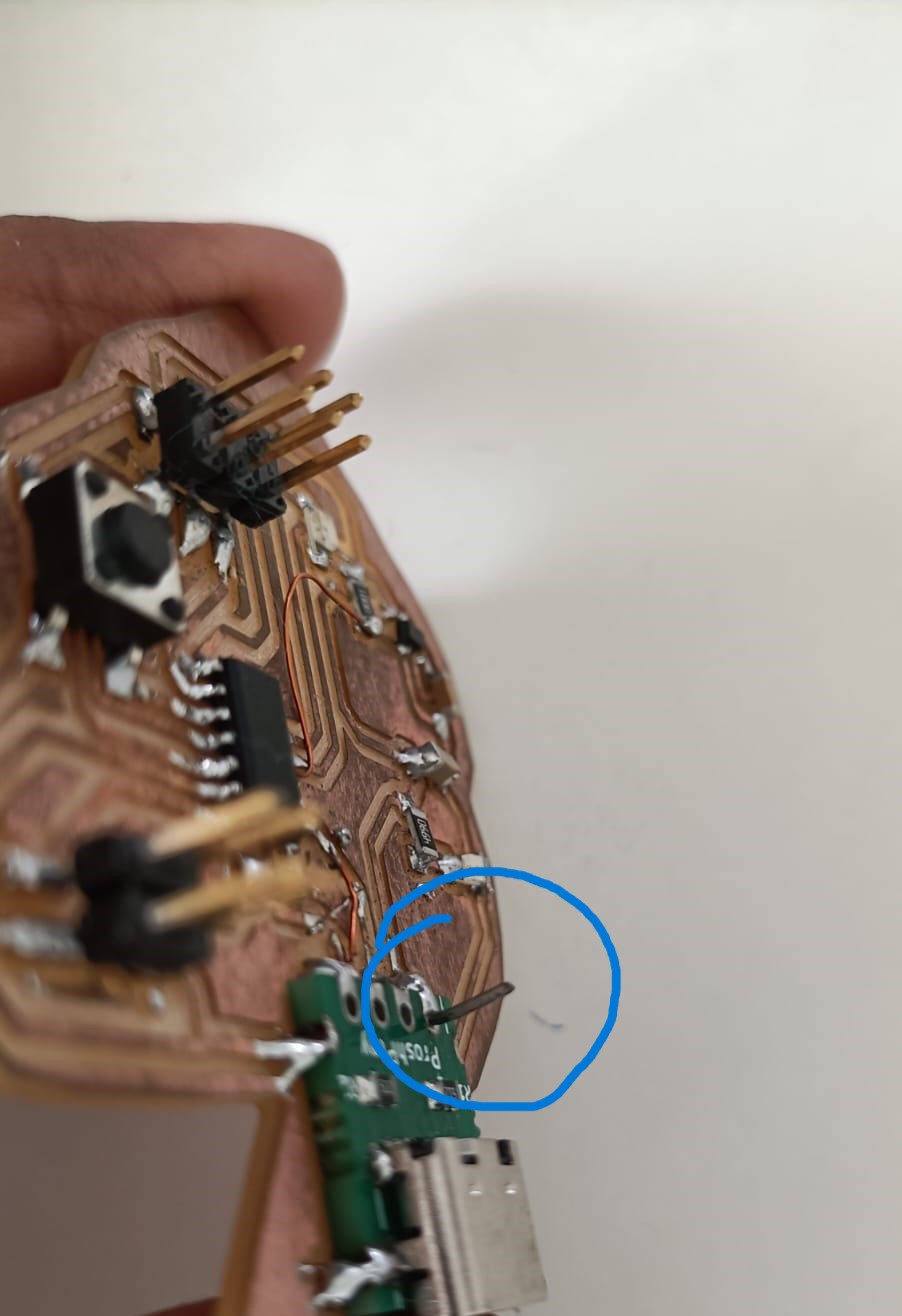
Problems faced during this
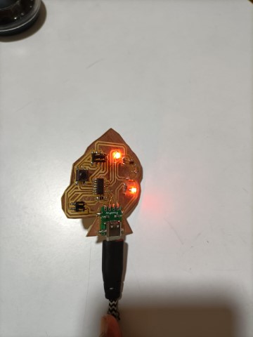
To check the LED blink
      void setup() {
        // initialize digital pin LED_BUILTIN as an output.
        pinMode(2, OUTPUT);

      }

      // the loop function runs over and over again forever
      void loop() {
        digitalWrite(2, HIGH);  // turn the LED on (HIGH is the voltage level)
        delay(1000);             // wait for a second
        digitalWrite(2, LOW);   // turn the LED off by making the voltage LOW
        delay(1000);             // wait for a second

      }
To check whether the LED blinks when you push the button
    const int buttonPin = 9;  // the number of the pushbutton pin
    const int ledPin_1 = 2;   // the number of the LED pin 1

    int buttonState = 0;  // variable for reading the pushbutton status
    bool pressed = false;
    void setup() {
      pinMode(ledPin_1, OUTPUT);  // initialize the LED pin1 as an output:

      pinMode(buttonPin, INPUT);  // initialize the button pin as an input:
    }
    void loop() {
      buttonState = digitalRead(buttonPin);  // read the state of the pushbutton value:
      if (buttonState == HIGH)               // check if the pushbutton is pressed. If it is, the button state is HIGH:
      {
        if (pressed == false) {
          pressed = true;
          if (digitalRead(ledPin_1) == LOW)  // check whether the led1 is off, if it is then the LEDs will be HIGH
          {
            digitalWrite(ledPin_1, HIGH);


          } else {  // if led1 is on then it will turn off all the LEDs
            digitalWrite(ledPin_1, LOW);
          }
        }
      } else {
        pressed = false;
        delay(50);
      }
    }
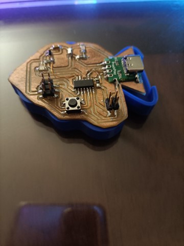
3D printing a case for the PCB
I exported the .SVG file from KiCad into Fusion and I designed a case and 3d printed it. Unfortunately, it was slightly smaller than the PCB. But atleast I can use it as a platform for my PCB.
Design files
kiCad filesPNG file1
PNG file2
Arduino files