Computer Controlled Machining
The assignments for this week:
- Group assignment :
- do your lab's safety training test runout, alignment, fixturing, speeds, feeds, materials, and toolpaths for your machine
- Individual assignment:
- make (design+mill+assemble) something big (~meter-scale)
- extra credit:don't use fasteners or glue
- extra credit:include curved surfaces
Group assignment:
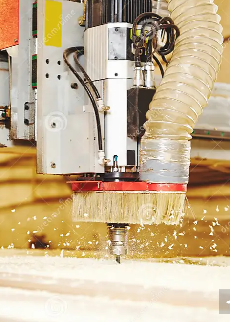
Computer Numerical Control(CNC)
Computer numerical control (CNC) is the automated control of
tools by means of a computer. It is used to operate tools such as drills, lathes, mills, grinders, routers and 3D
printers. CNC transforms a piece of material (metal, plastic, wood, ceramic, stone, or composite) into a specified
shape by following coded programmed instructions and without a manual operator directly controlling the machining
operation.
A CNC machine is a motorized maneuverable tool and often a motorized maneuverable platform, which are both
controlled by a computer, according to specific input instructions. Instructions are delivered to a CNC machine in
the form of a sequential program of machine control instructions such as G-code and M-code, and then executed. The
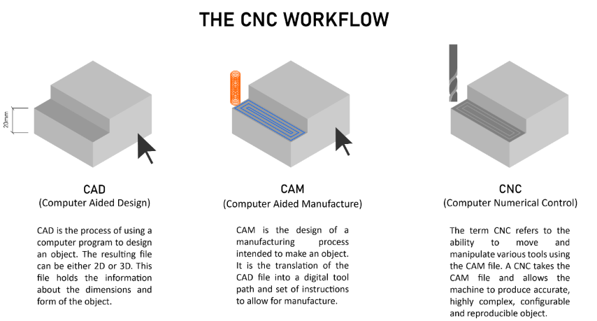
program can be written by a person or, far more often, generated by graphical computer-aided design (CAD) or
computer-aided manufacturing (CAM) software.
Source:https://www.making.unsw.edu.au
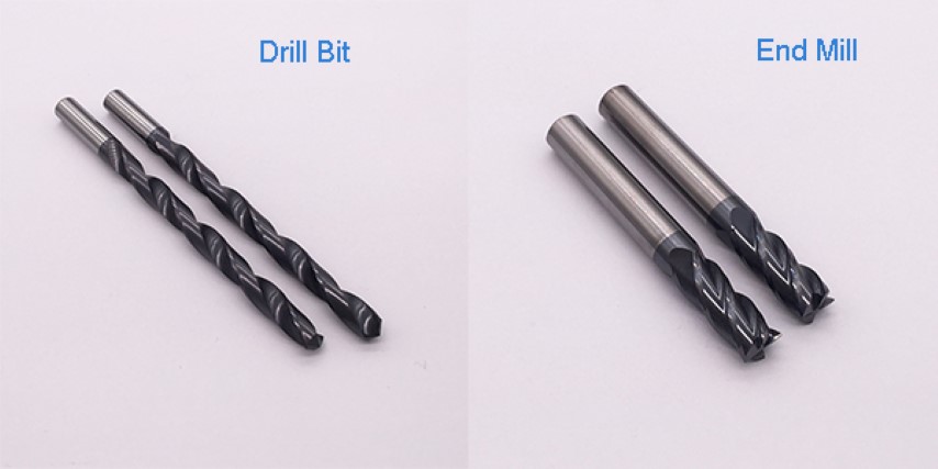
Types of cutting tools
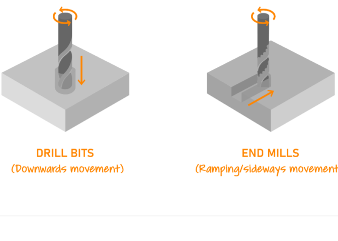
There are two basic kinds of cutting tools for the ShopBot: drill bits and end mills.
Drill bits: These are the same bits used in a hand drill or drill press.
They are only for drilling holes, and only work when moving straight down.
End bits:These bits are designed to cut while moving sideways through the material.
There are two common styles of end mills, regular and ball end.
A regular end mill has a flat end, and is used for cutting at surfaces.
A ball end mill has a hemispherical end, and is used for 3D machining and finishing passes.
Types of flutes
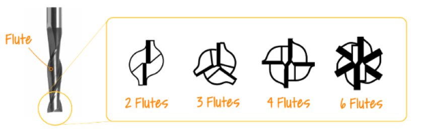
Cutting tools have two parts, the shank and flute.
The flutes are the cutting edges of the bit. The shank is the section that goes into the tool holder.
The shank must always be the same diameter as the tool holder. The flutes may (or may not) be the same diameter as
the shank.
Flutes feature grooves or valleys that are cut into the body of the tool. A higher number of flutes increases the
strength of the tool and reduces space or chip flow. End mills with less flutes on the cutting edge will have more
chip space, while end mills with more flutes will be able to be used on harder cutting materials.Flutes are the
cutting surface of an end mill. These deep spiralled grooves allow for chip formation and excavation assiting in
the cutting of the material.
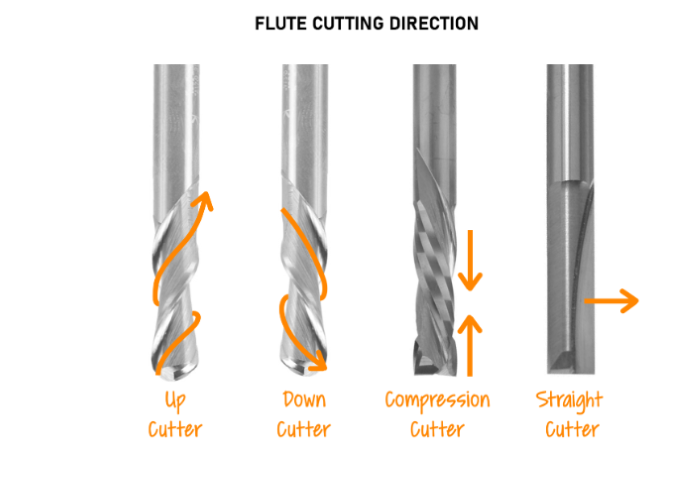
Based on flute cutting direction:Some bits are available as up-cut, down-cut or compression spiral.
Up-cut :
Sawdust is ejected from the top of the workpiece.
They damage the top layer of material.
They tend to lift the workpiece off the table. Be careful with workholding.
Down-cut :
Sawdust is pushed into the workpiece.
They push the workpiece down onto the table.
Compression spiral :
A combination bit (down-cut on top & up-cut on the bottom) designed to cut all the way through sheetgoods in a
single pass.
Based on number of flutes:The number of flutes on an end mill determines chip size and surface finish. More
flutes equals better surface finish, but means the tool runs at a higher heat and isn't suitable for all
materials. Fewer flutes means greater chip size and more clearing capacity
Single Flute designs are used for high-speed machining and high-volume material removal.
Two Flute designs have the most amount of flute space. They allow for more chip carrying capacity and are used
primarily in slotting and pocketing nonferrous materials.
Three Flute designs have the same flute space as two flutes, but also have a larger cross-section for greater
strength. They are used for pocketing and slotting ferrous and nonferrous materials.
Four/Multiple Flute designs allow for faster feed rates, but due to the reduced flute space, chip removal may be a
problem. They produce a much finer finish than two and three flute tools. Ideal for peripheral and finish
milling.
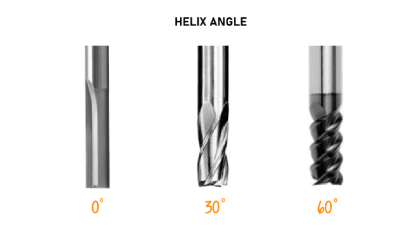
Based on helix angle:
Flutes with a higher helix angle pull the chip out more aggressively, which is useful for materials where chip
removal is crucial (e.g. metals). For softer materials like wood, a lower helix angle (or a straight fluted tool)
can produce a nicer edge finish.
Chip load
Chip load is defined as the thickness of the chips removed during a machining operation.
Chip Load = Feed Rate
(inches per minute) / (RPM x number of flutes).
Setting machining parameters to ensure optimal chip load improves
machining quality and prolongs tool life.It can also be defined as the maximum load that a cutting tool such as
router bits, can withstand without degrading the tool's life.
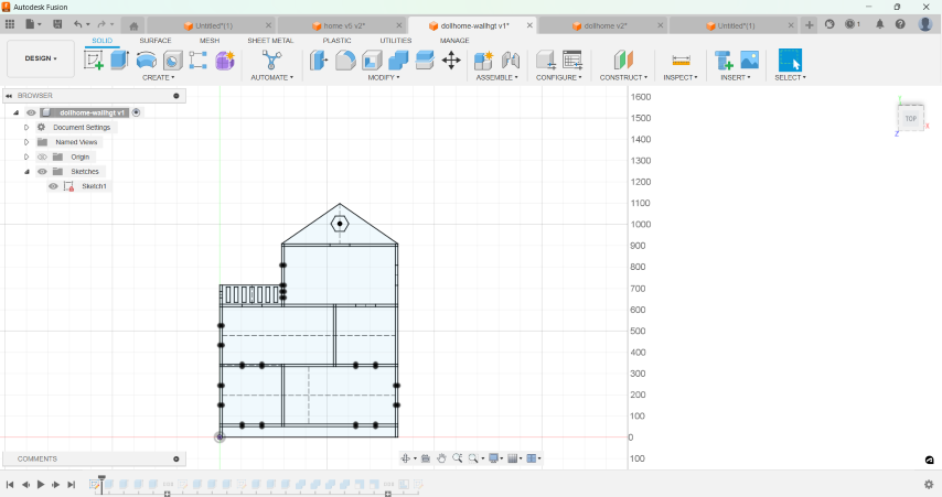
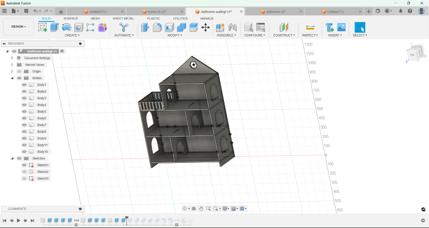
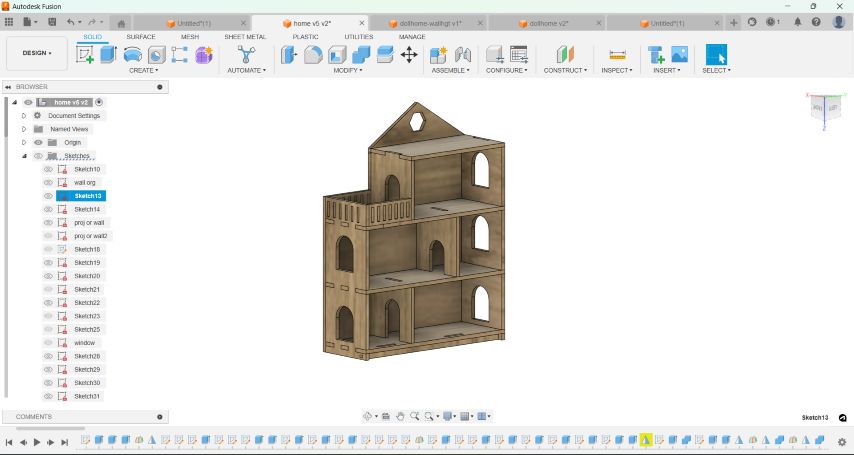
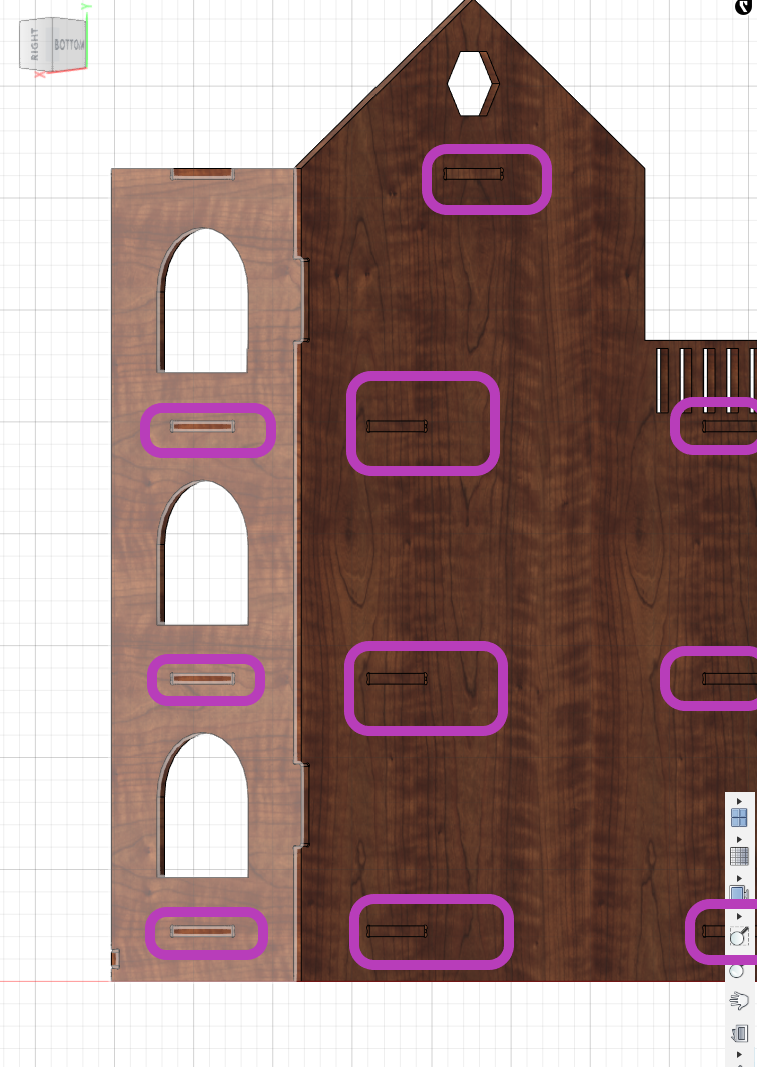
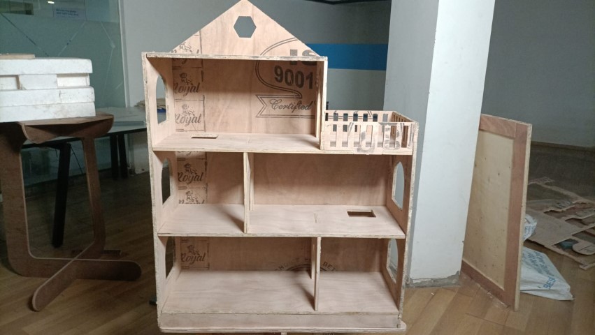
Designing a dollhouse
- Using parameters for the plywood thickness,length, width and level height, I sketched the section of the house.
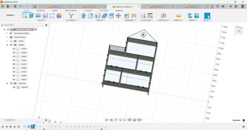
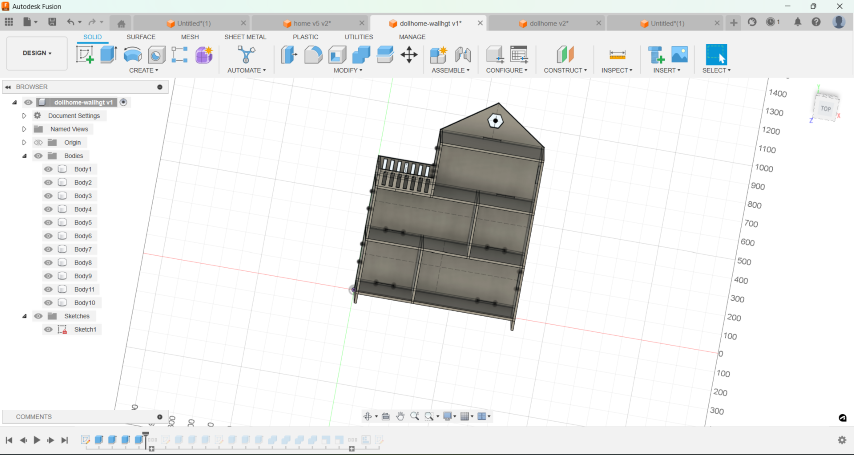
- Once i finished sketching, I used the extrude tool to create the basic structure of the dollhouse.
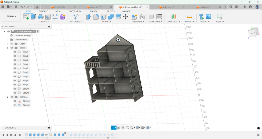
- Then, I created sketches for walls, windows, and doors on appropriate planes and extruded the sketches to create walls, windows, and doors.
- I added railings for the balcony.
- I added tabs and slots for the joints.
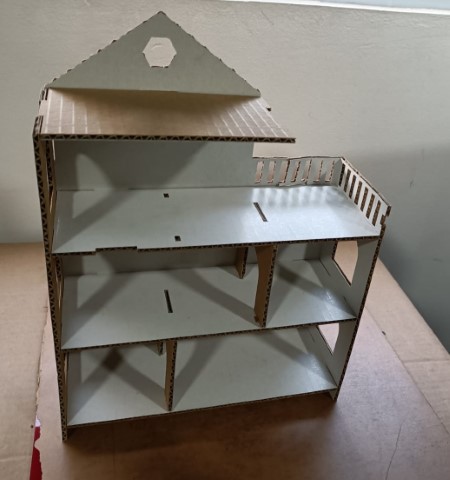
- Before milling, I decided to make a test piece in cardboard using Zund.
- Exporting to dxf:
- Convert the bodies to components by right clicking on bodies
- Arrange the components in the desired orientation and layout. Also, the "Arrange" option in "Modify" can be used.
- Click on the "Sketch" menu and select "Create Sketch" to start a new sketch on the desired plane or surface containing the geometry to export.
- Next, project existing geometry into the sketch
- Once traced the geometry can be exported as dxf from the sketch.
- Creating a mockup for my project involved designing a parametric model, which allowed for easy adjustments and scaling. For the initial prototype, I scaled down the design and cut it from cardboard using a Zund machine. This step helped me visualize and refine the final product before moving on to machining in wood. The steps involved in making this parametric in Zund and how to use the machine can be found in Week 3, Computer Controlled cutting
.png)
Joints
In my design, I used both chamfer and dogbone features to ensure the joints and edges were precise and functional.By combining chamfer and dogbone features in my design, I was able to enhance both the functionality and appearance of the joints. Chamfers made the edges more robust and easier to handle, while dogbone fillets ensured precise and secure interlocking joints.Nifty dogbone
Dogbone fillets are used to create sharp internal corners, which are otherwise impossible to achieve with round cutting tools.This feature ensures that square or rectangular tabs can fit precisely , making the joints more secure and structurally sound. I used dogbone fillets on internal corners of the joints. This allowed the tabs to fit perfectly into the corresponding slots, ensuring a tight and stable assembly.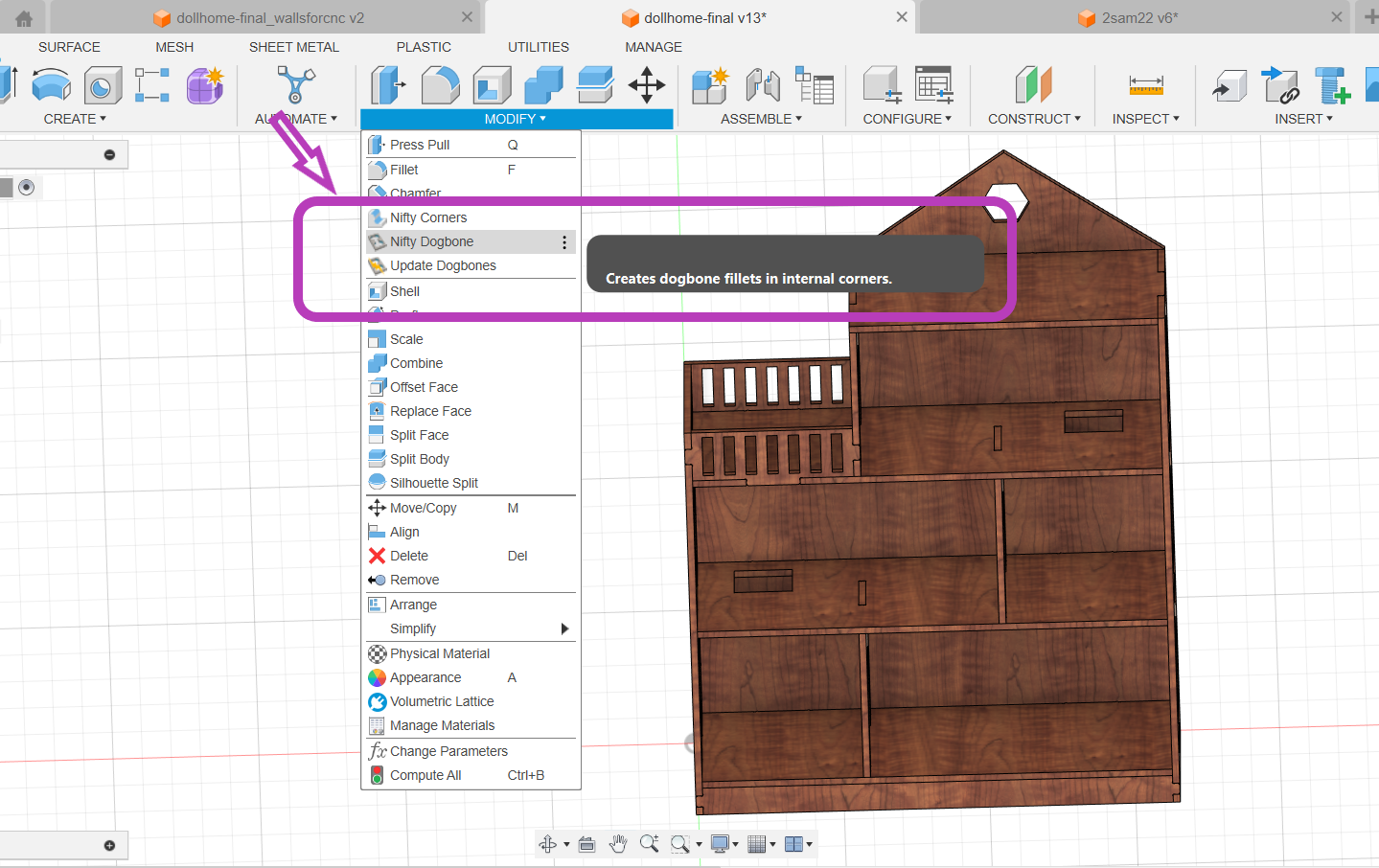
.png)
Chamfer
Chamfers are used to bevel edges, removing sharp corners and creating a sloped edge. This helps in easing the assembly process, reducing stress concentrations, and preventing the edges from chipping or cracking. Chamfers also improve the aesthetic quality of the design by providing a more finished look. I applied chamfers to edges where two surfaces meet, ensuring that the pieces fit together smoothly and securely..png)
.png)
Steps involved in milling using the Shopbot CNC router
Unfortunately, it was not possible to mill and assemble my design before the end of the cutting week. Here are the steps involved :- Design: Create or obtain a digital design file (CAD, CAM, or vector-based) of the object you want to produce. Ensure it's compatible with the ShopBot software.
- Material: Choose the material to be working with and ensure it's securely fixed to the CNC machine's bed.
- Tooling: Select appropriate cutting tools (bits) based on the design and material.
- CAD/CAM Software: Use a compatible software program to generate toolpaths from your design file. Popular options include VCarve, Aspire, Fusion 360, etc.
- Toolpath Generation: Set up toolpaths, specifying cutting depths, speeds, and other parameters according to the material and design requirements.
- Generate G-code from your toolpaths using the CAM software. This G-code will control the CNC machine's movements.
- Load G-code: Transfer the generated G-code file to the ShopBot CNC machine via USB, network connection, or other means.
- Tool Installation: Install the appropriate cutting tool(s) into the spindle of the CNC machine.
- Workpiece Alignment: Use the machine's controls to move the spindle to the starting position and set the origin point (zero reference) for your job. Ensure proper alignment of the tool and the workpiece.
- Run Job: Start the CNC program from the machine's control interface. The machine will follow the instructions in the G-code to cut or carve your design into the material.
- Monitoring: Keep an eye on the machine during operation to ensure everything is running smoothly. Be prepared to pause or stop the job if necessary.
- Finishing: Once the CNC job is complete, remove the finished workpiece from the machine bed.
- Cleanup: Remove any excess material or debris from the work area and machine.
- Quality Check: Inspect the finished product for any defects or imperfections. Make any necessary adjustments for future jobs.
- Tool Maintenance: Clean and properly store cutting tools after use. Replace worn-out or damaged tools as needed.
CAM-Vcarve
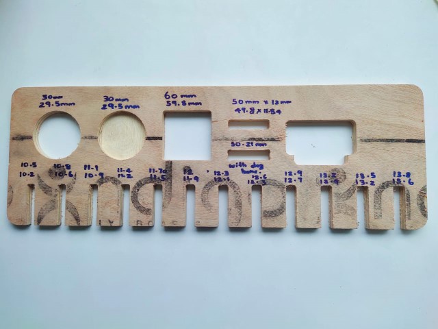
VCarve is a popular CAM (Computer-Aided Manufacturing) software developed by Vectric, designed for creating toolpaths for CNC (Computer Numerical Control) machines like the ShopBot. It is widely used in woodworking, sign making, and other CNC machining applications.After importing the .dxf file into VCarve and I set the basic parameters, including job size, origin, and material thickness. Using a vernier caliper, I measured the plywood thickness which varied between 11.6mm and 12.1mm, so I set the thickness to 12mm in the software..png)
There are three milling parts: Drill (Pre-drill)
.png)
.png)
Then, I specified the Inner Cut and Outer Cut.
.png)
Specify the dimensions of the tabs, including their width and height. These should be large enough to hold the pieces securely but small enough to be easily removed later. Choose the locations for the tabs. VCarve may allow you to place tabs automatically or manually. Ensure tabs are placed at intervals that provide stability without excessive material waste.
.png)
.png)
ShopBot PRS Alpha 96 CNC Router
The ShopBot PRS Alpha 96 CNC Router is a powerful and versatile machine used for various applications in woodworking, metalworking, and other materials. Here are the specifications for the ShopBot PRS Alpha 96:Z Axis: Up to 300 IPM
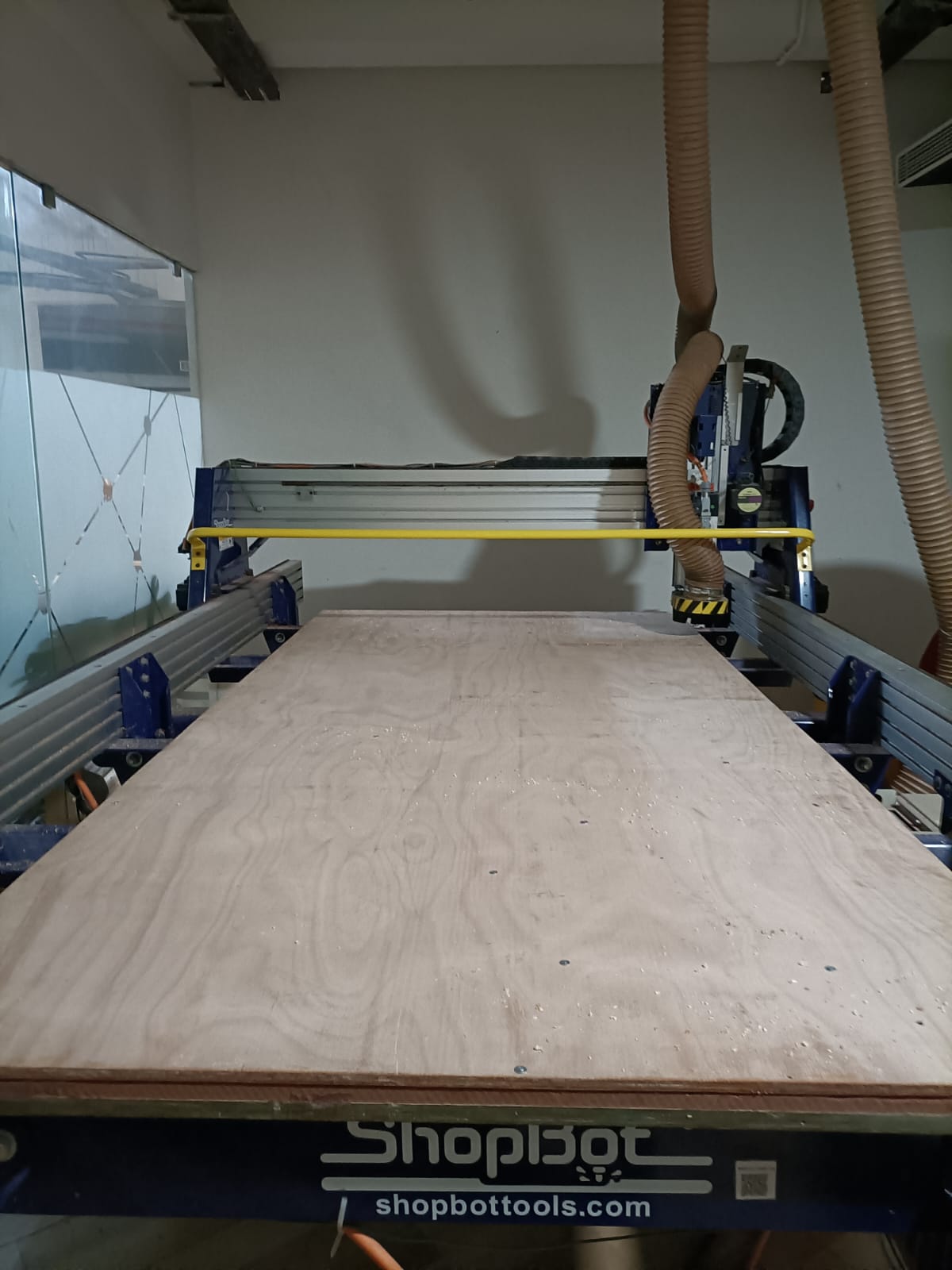
The next step is to set the origin. To do this, jog the module along the X and Y axes to establish the zero position. For the Z axis, the machine uses a plate and an alligator clip. When the clip and metal plate come into contact, the machine automatically detects the position and sets the Z axis's zero point.
.JPG)
.JPG)
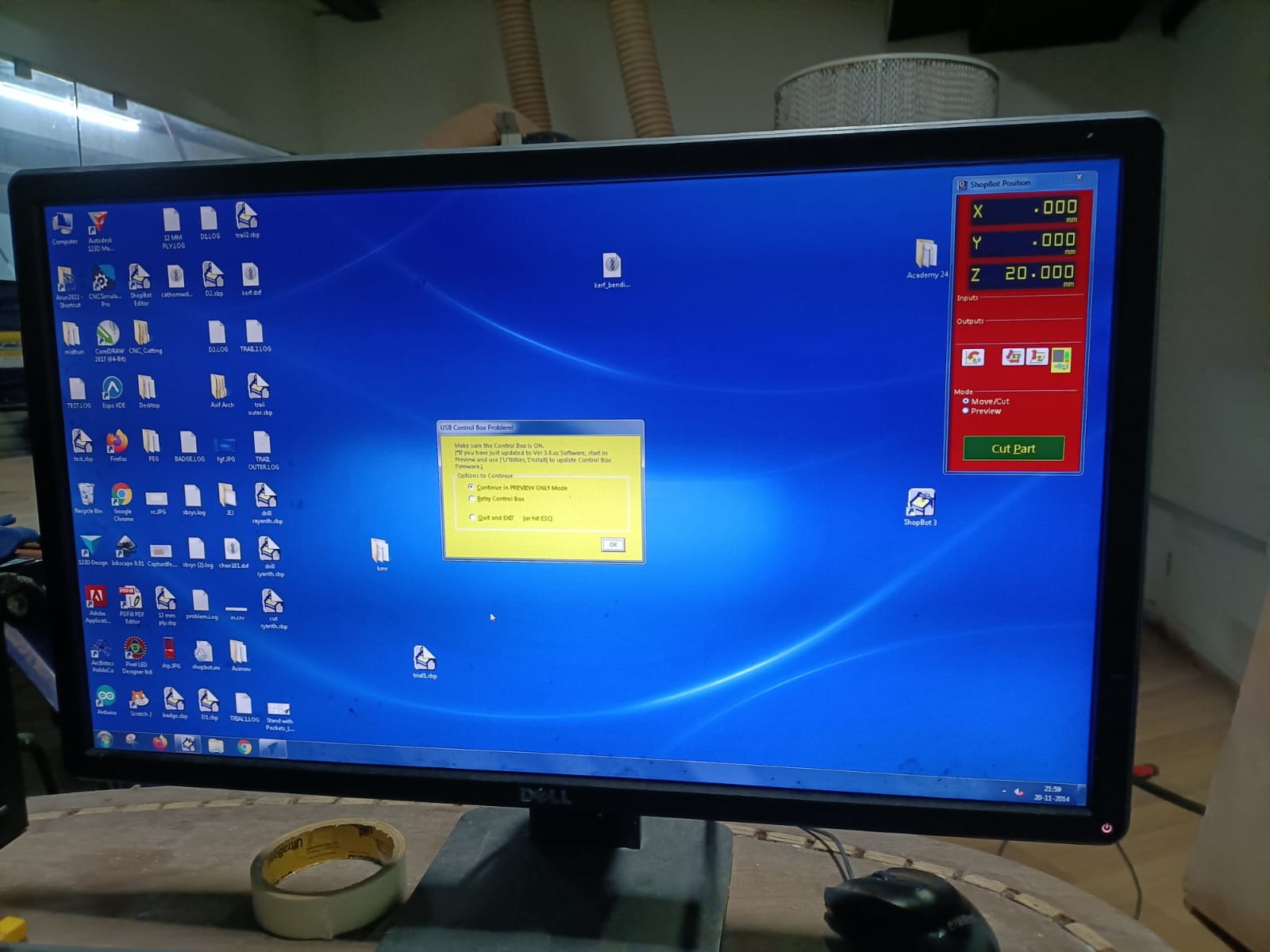
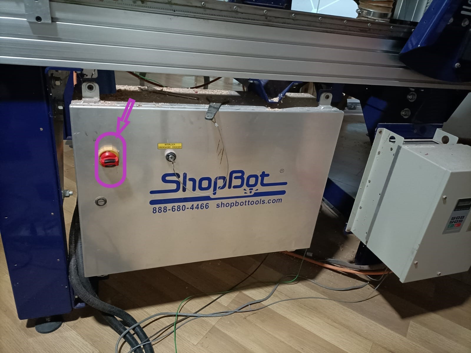
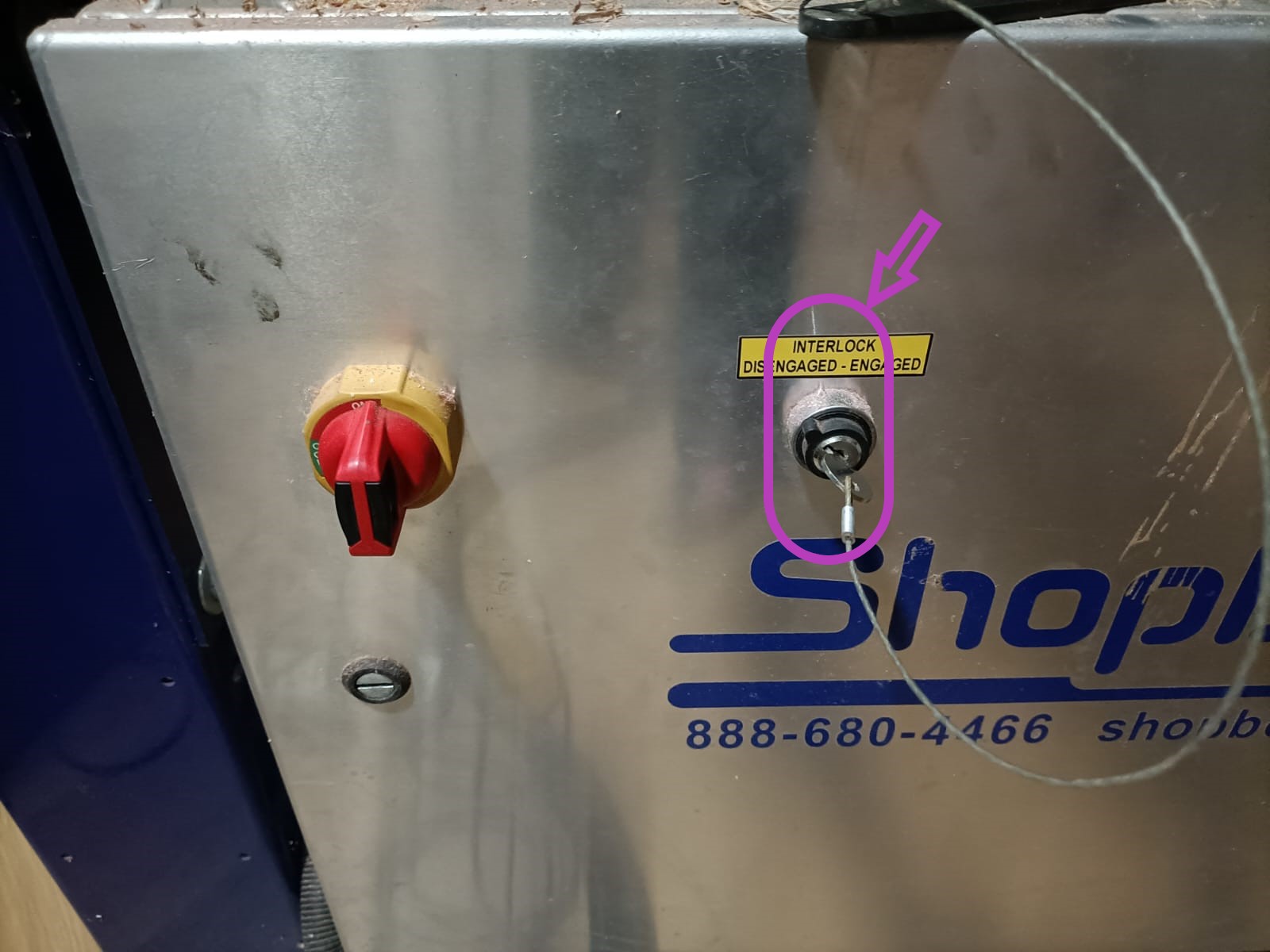
Once all three axes are zeroed, click on "Cut Part" to upload the file. Then, click "Start," and a pop-up box will appear requesting you to turn on the spindle. To do this, turn the key on the machine's side panel once.
.JPG)
And then the work begins.
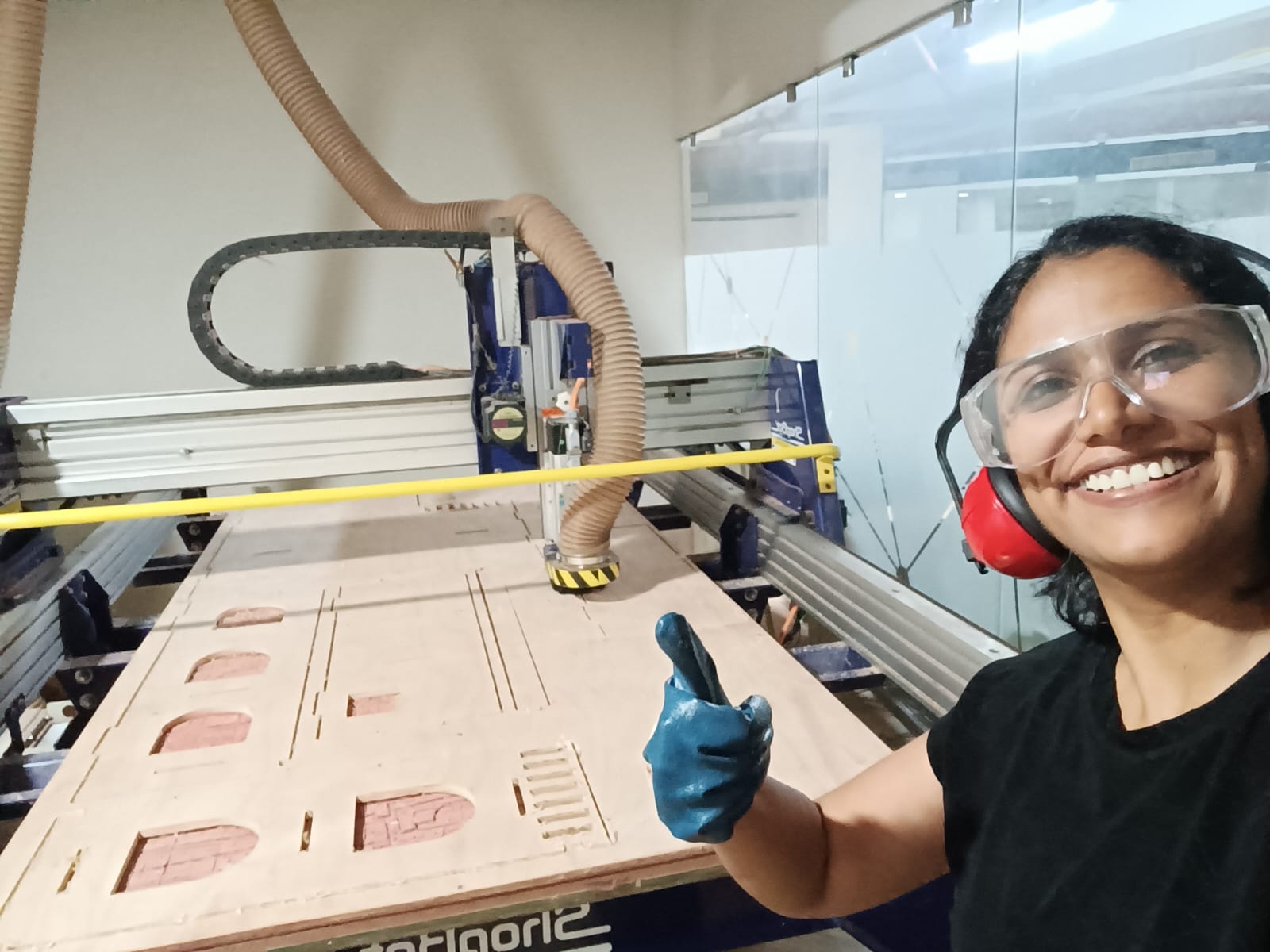
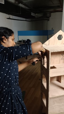
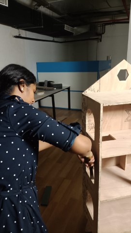
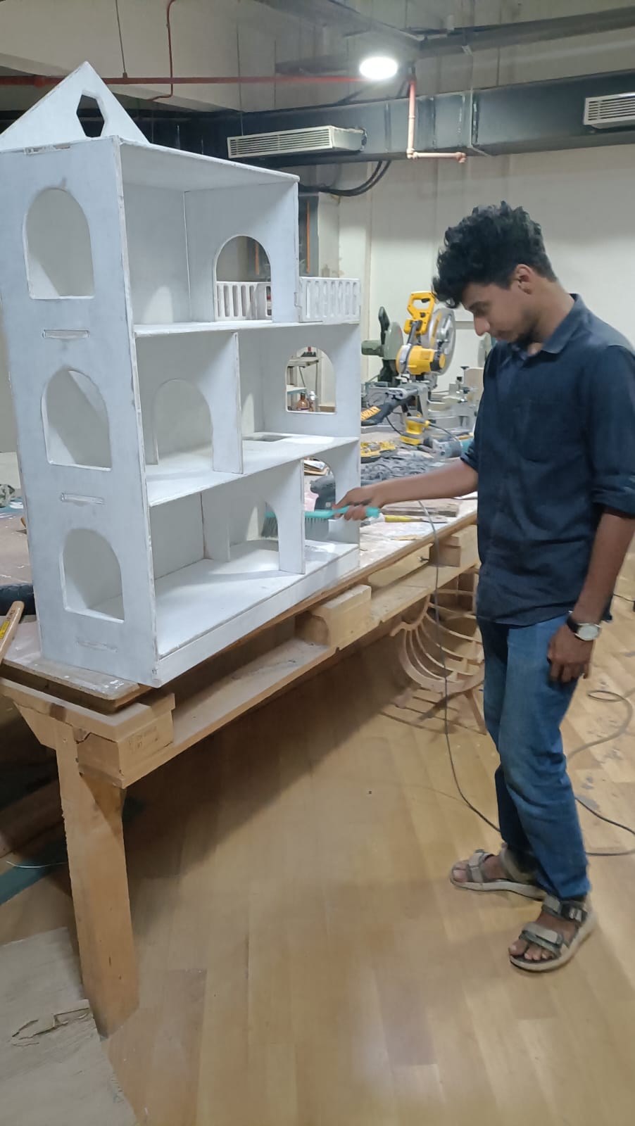
Assembly begins...
Since most of the joints have to be press fit at the same time, I was worried whether they will fit in at the same time. But it was quite easy assembling it. Thanks to Mufeed who helped me do this easily!
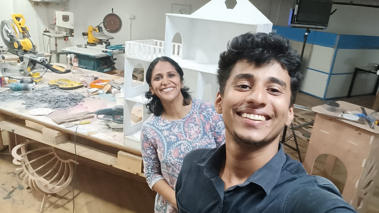
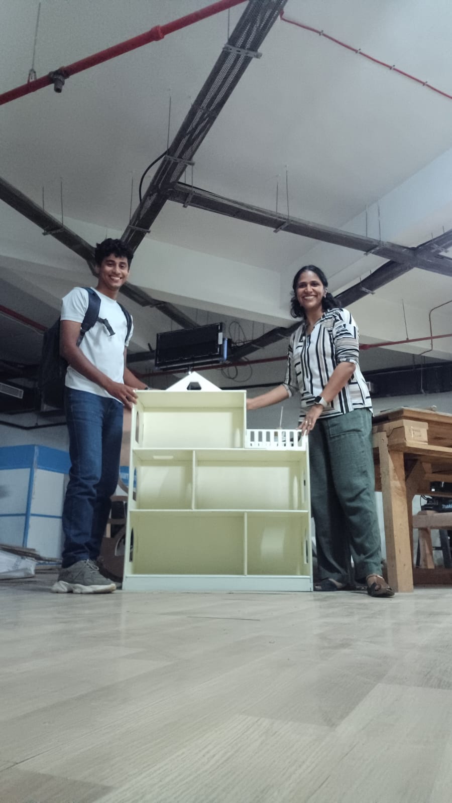
Finally!!!
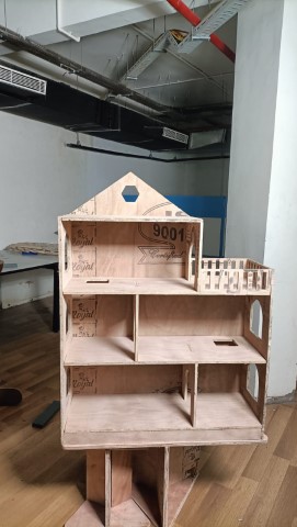
Final Touches
Preparing the surprise for my daughter
I wanted to surprise my daughter with the dollhouse. But it was kept against a damp wall and it got fungus on it and I had to treat it and use it for my kid. The steps I followed :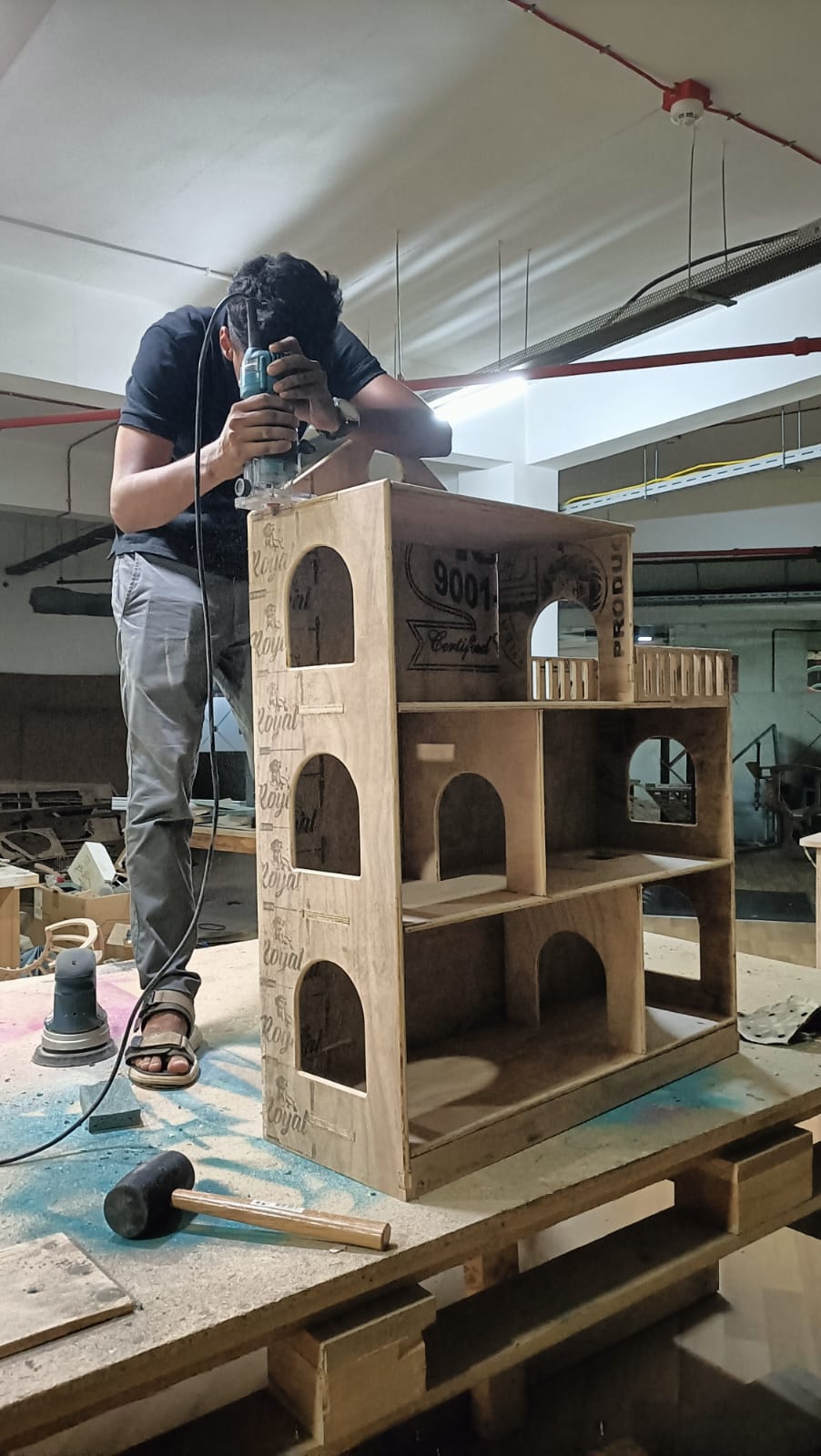
Design files
Dollhouse_step fileShopbot Cut files