Computer Controlled Machining
Assignments
- Group Assignment
- do your lab's safety training
- test runout, alignment, fixturing, speeds, feeds, materials, and toolpaths for your machine
- Document your work to the group work page and reflect on your individual page what you learned
- Individual Assignment
- make (design+mill+assemble) something big (~meter-scale)
Hero Shots
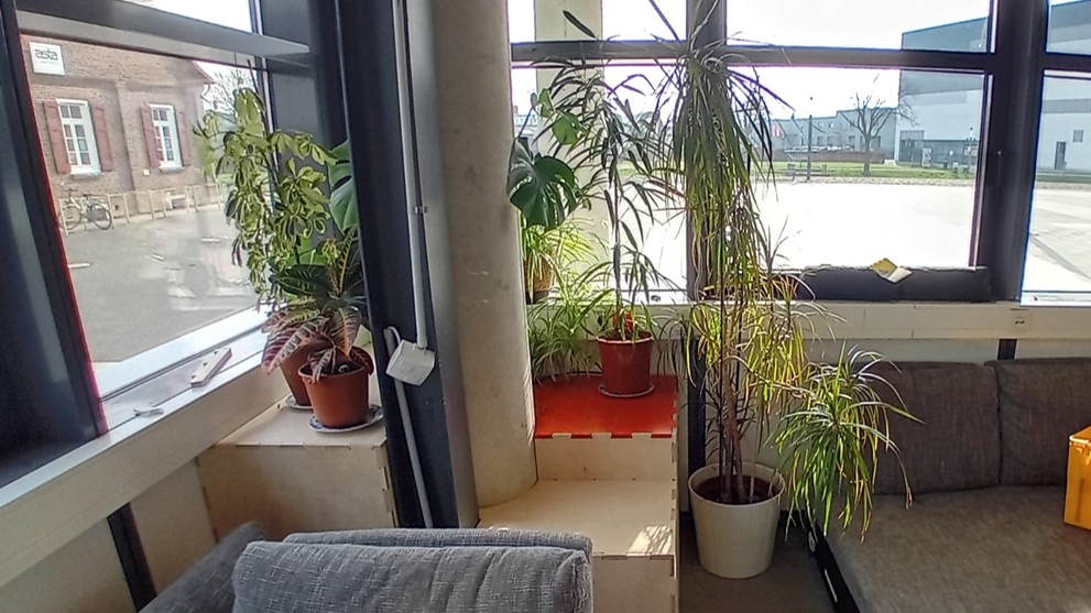

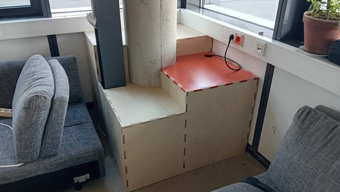
Group Assignment
CNC Milling
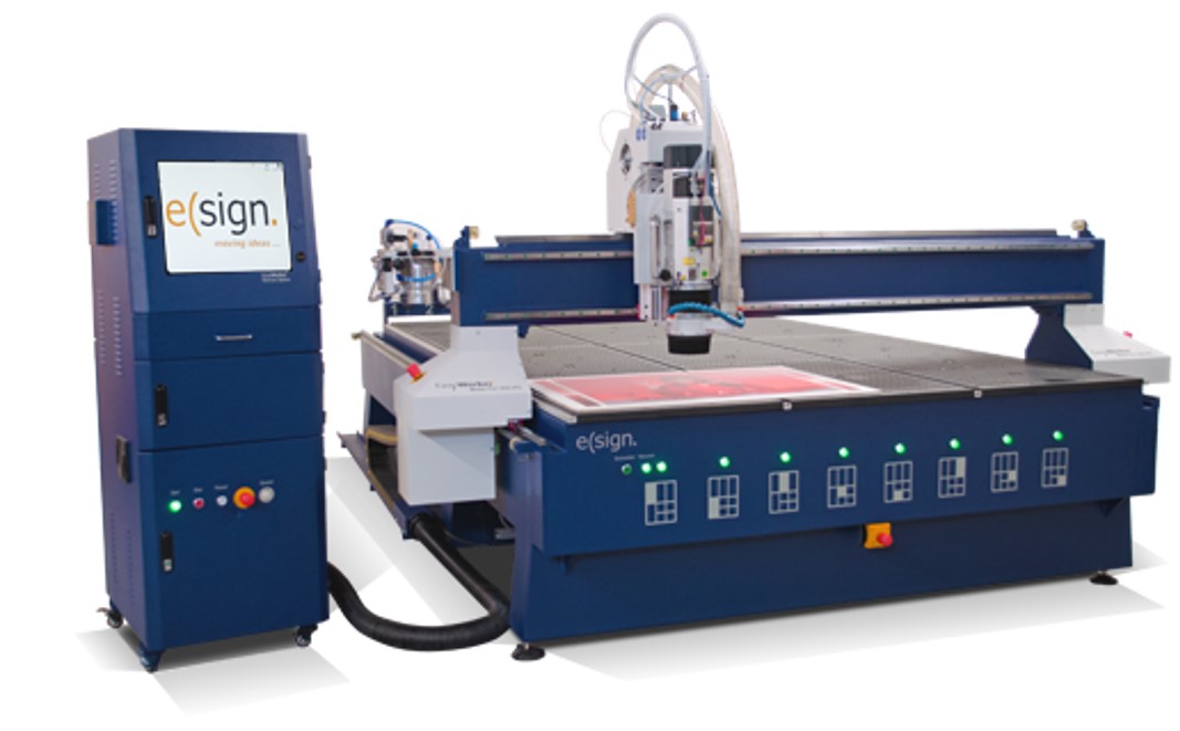
For the group assignment and working on the CNC we were introduced to the CNC machine (eLsign EasyWorker MasterPro 2513). The machine includes the CNC milling machine (3 axis), a CNC bed of 2500mm x 1300mm x 200mm, a vacuum for fixture of the sacrificial layer and the used material to cut, and a computer station, that includes the software to operate the machine. For any further information about the machine take a look into the group assignments page (see here).
Safety Instruction
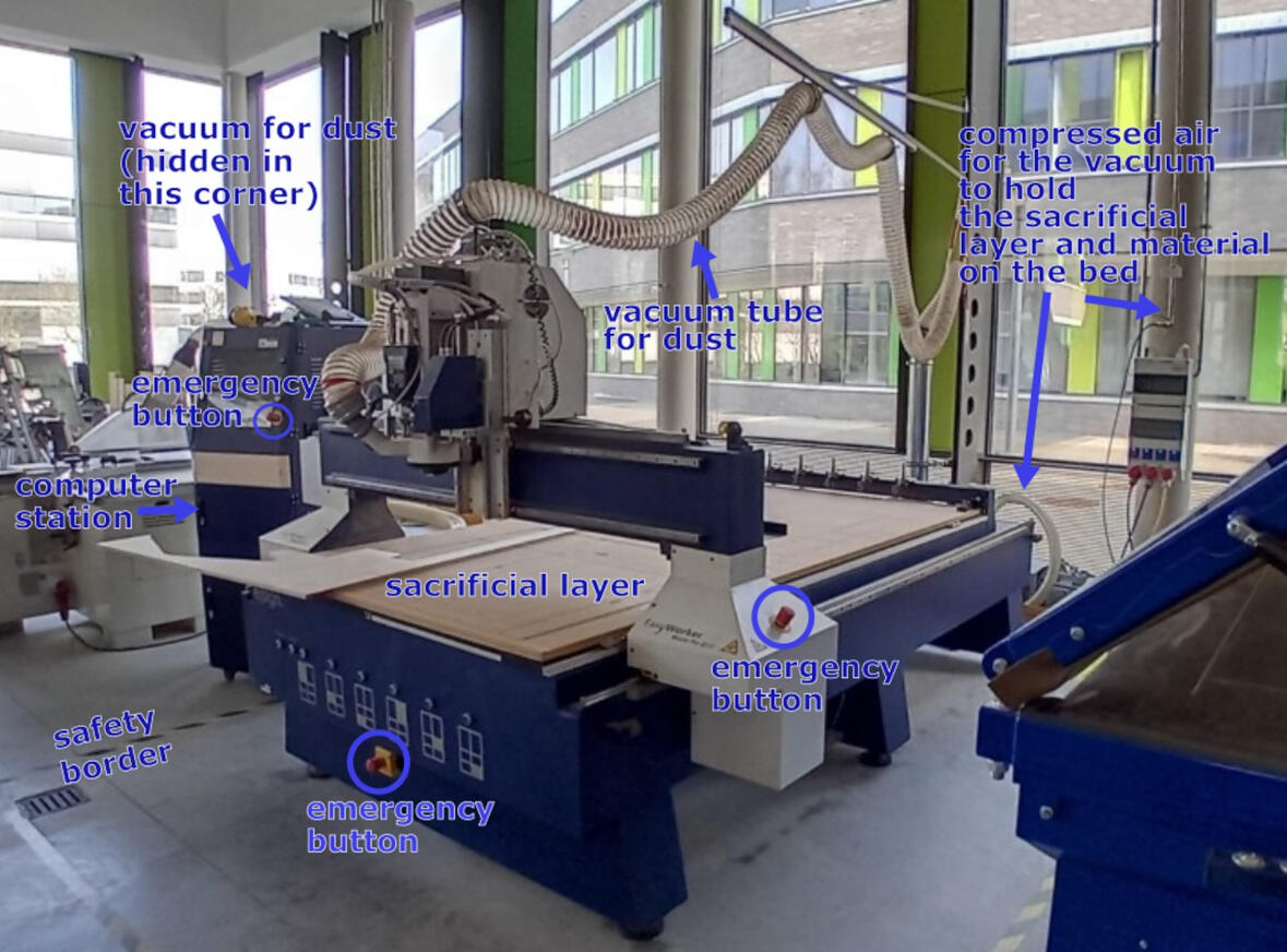
The most important part about working on the CNC machine is safety. The machine is only allowed to be operated, when:
- You had the safety instruction
- Other people are in the lab to help you in case of an accident
- one of hte senior instructors is in the lab
- Watch the machine
- Are able to reach a emergency button
- Stay outside the marked area (safety border) around the machine
- Wear earbuds and protective eye gear
Setup and Control
The detailed description about the setup and the control of the machine is described in the group assignment.
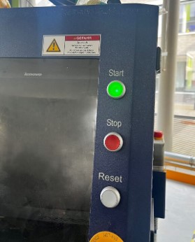
However, there are some important things I want to highlight in this chapter. After you laid the sheet of material on the bed and additionally secured it with clamps, and you want to start a job, check for these things:
- Turn on the high pressure valve
- Turn on the machine with the main switch on the side of the computer station
- Press reset on the computer station
- Press start on the computer station
- Turn on the dust collector in the corner
- Check if the correct path of the dust collector is open
- Turn on the computer
- Start the software
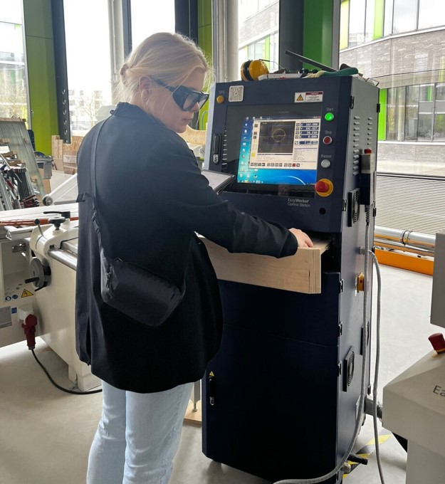
After starting the software, there different things you need to encounter:
- When the last job ended with an emergency stop or did not properly ended in some other way, the automatic tool exchange is not working correctly
- Pick up a tool (press F11, then F6)
- Check the length of the tool with the machine (sensor on the right corner next to the tools)
- Set z-axis zero (with leveling tool or manually)
- Do a test cut with your spindle speed and low feeding rate, to see if the setup you are using in your CAM is going to be the right one
- Listen carefully to the sound of the machine to ensure the right parameters
- Set the right zero for x and y axis
- Upload your job and start it
Computer Aided Manufacturing
In our CAM processes, we employed Fusion 360. To thoroughly assess runout, alignment, fixturing, speeds, feeds, materials, and toolpaths, we designed test pieces for comprehensive testing.
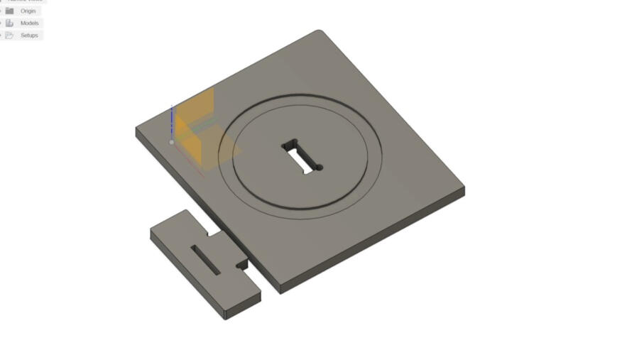
The test components include a plate designed for 2D carving (a concentric circle to assess carving precision), a rectangular hole is incorporated to conduct fitting tests with various types of dog bones, and an outcut. A corresponding piece is provided to insert into the hole, facilitating an examination of the fit. This piece additionally, includes a line in the middle to test drilling.
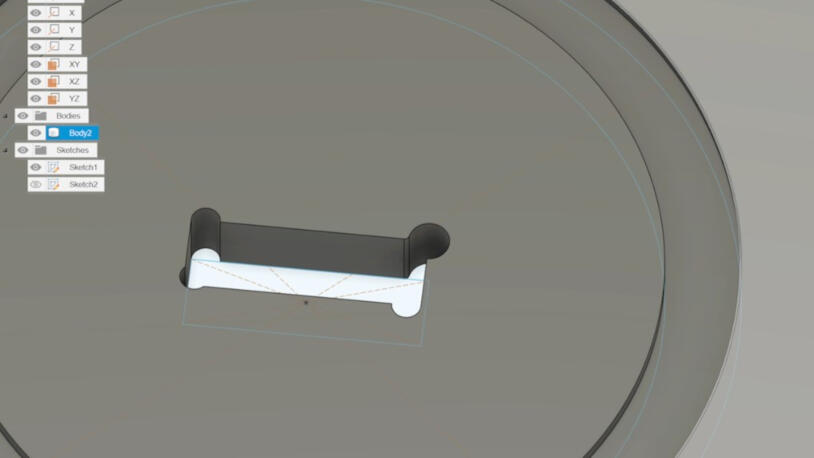
Depending on individual preferences and design constraints, various types of dogbones can be incorporated. These considerations are particularly crucial, as CNC machines are unable to cut angles under 180°. IT is crucial to consider the tool diameter in the design of the dog bones as the dog bone diameter should be equal are more than the tool diameter.
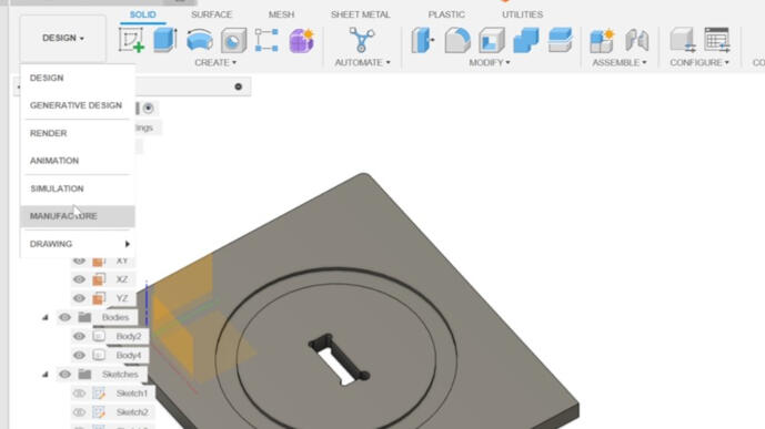
The next step is to switch the workspace to "Manufacturing".
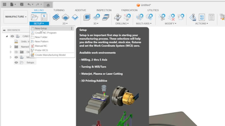
A new setup has to be created.
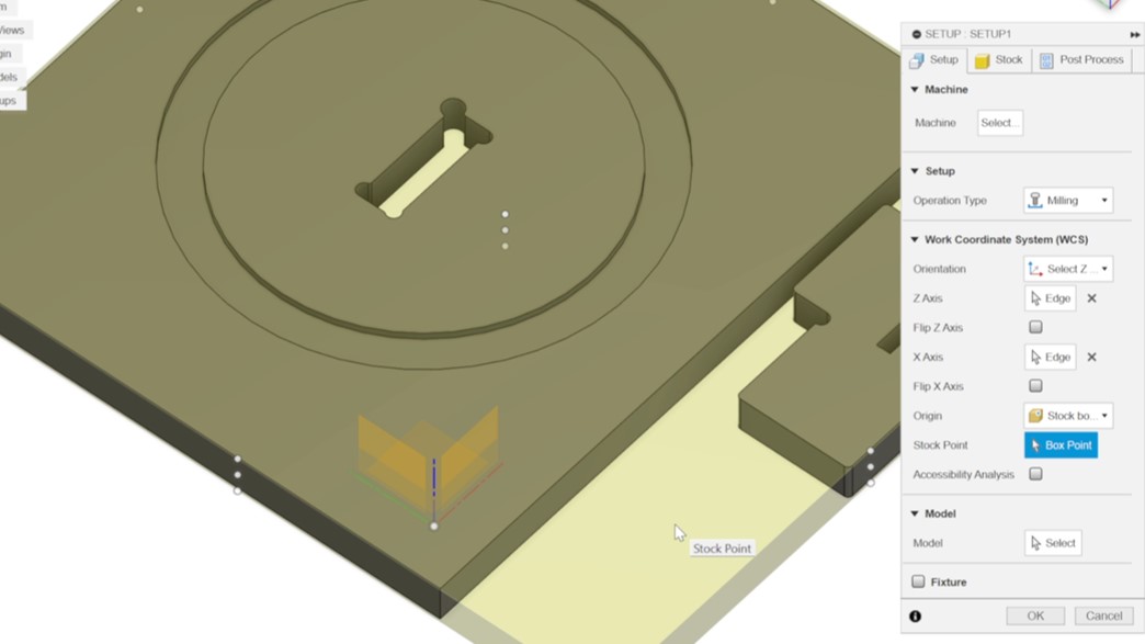
In the setup process, you have the option to select a machine from the library, provided it is available. Additionally, it is recommended to set the origin at one of the edges of the stock and place it at the bottom of the design. In the machine used the longer axis is the the x-axis. Alternatively, you can choose specific models to include in the manufacturing process. By default, all bodies are included.
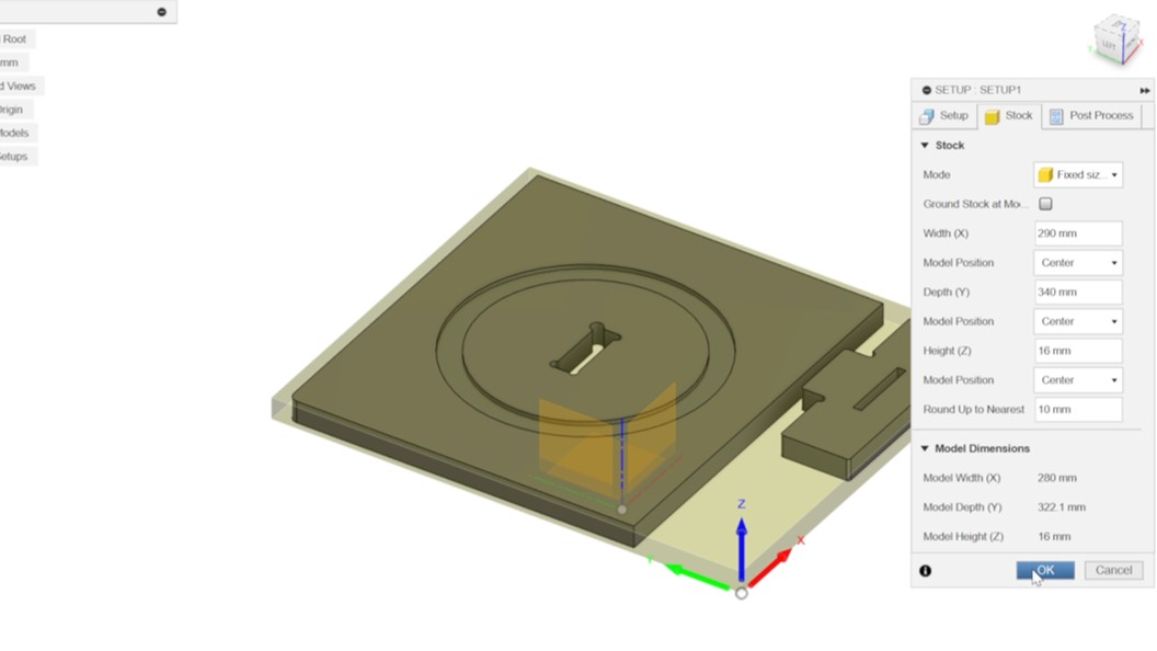
Go to the tab "Stock". In default the mode is "relative size box", change it to "absolute size box" and set the preferred values. Height should be the material thickness. After that, you can click on "OK".
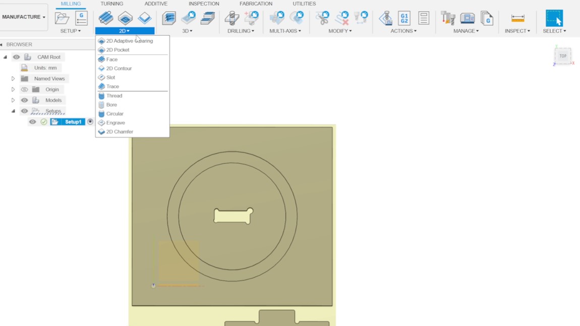
Click on "2D" and choose "2D Pocket", which will open a window on the right side.
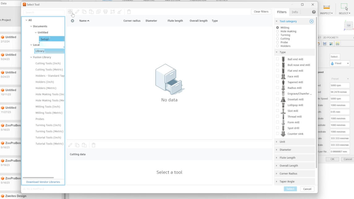
Click on "Select" next to the tool. A window occurs. Click on "Library" and the "plus symbol" in the right upper corner of the window.
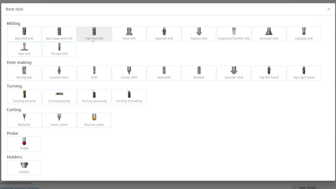
You can choose a tool profile. We used the "Flat end mill" profile.
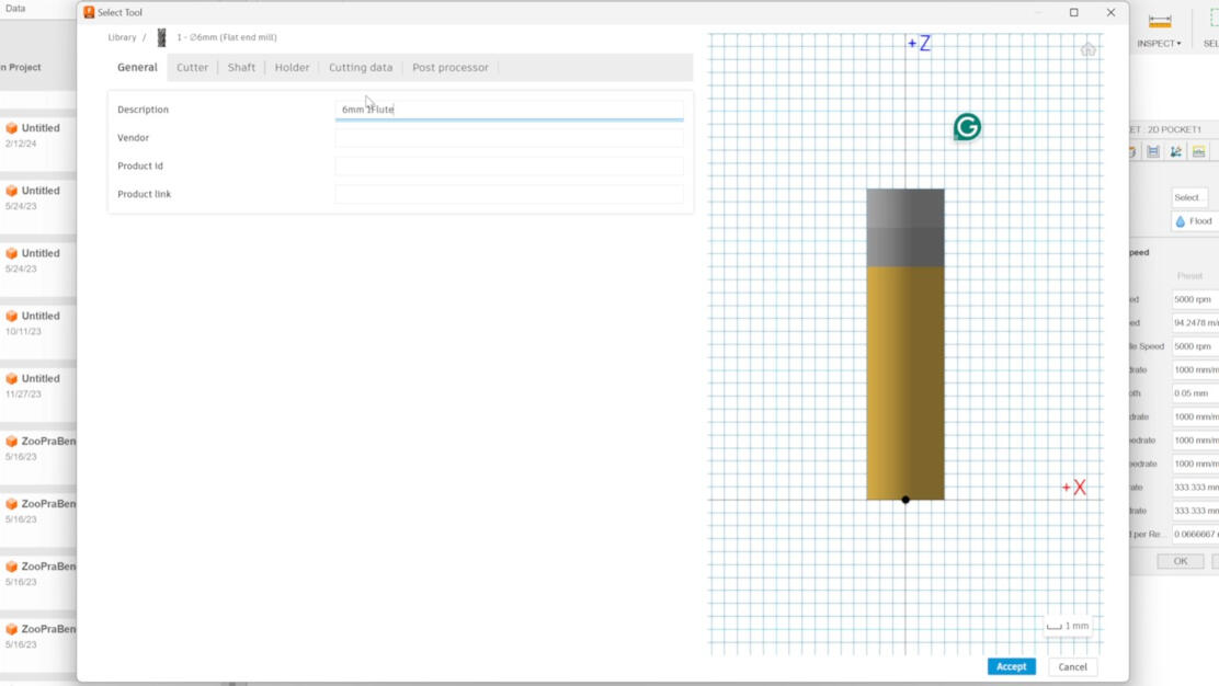
Next step is to describe the tool in a way you are able to identify the tool easily. A good way is to start with the diameter, then the flute, and the type of material to cut.
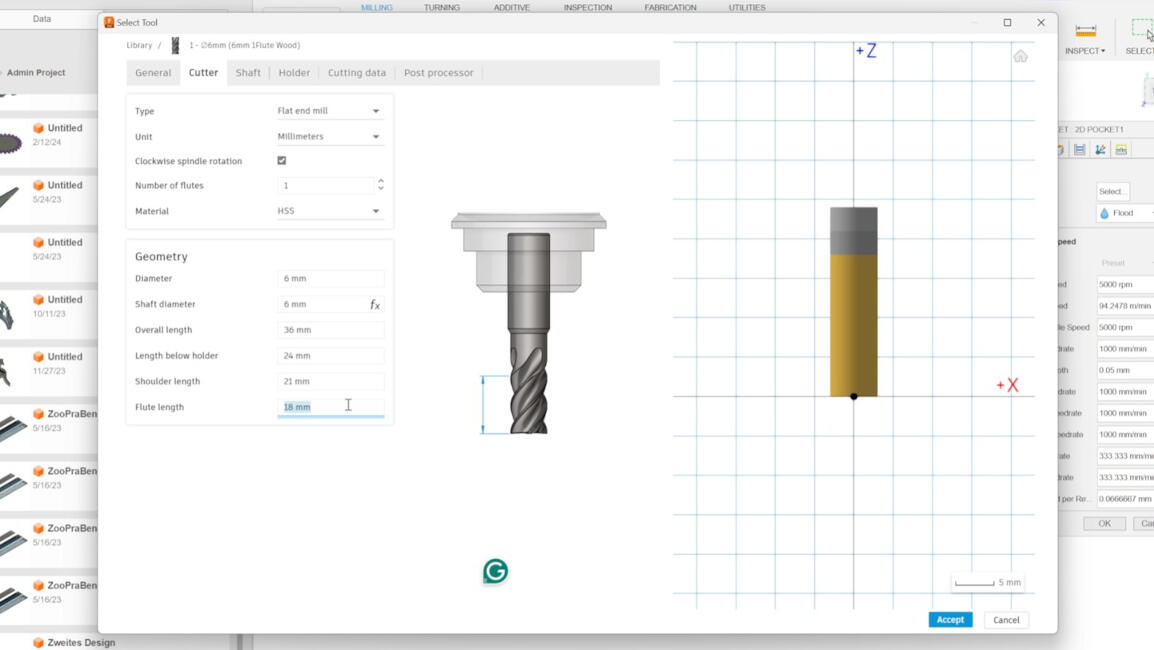
Go to "Cutter" tab. Here you can specify the parameters of the milling tool and tool holder. We used the parameters shown in the picture.
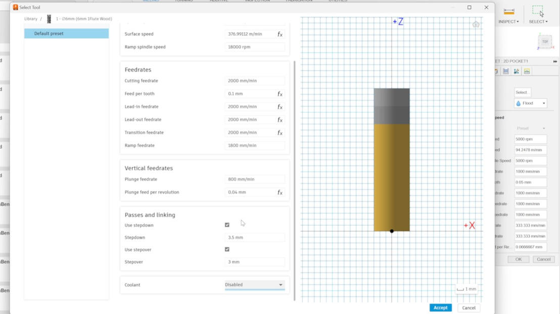
Go to the tab "Cutting data". Here you can enter the rpm, the feeding rate, etc. We used the parameters shown in the picture. After that, click on "Accept".
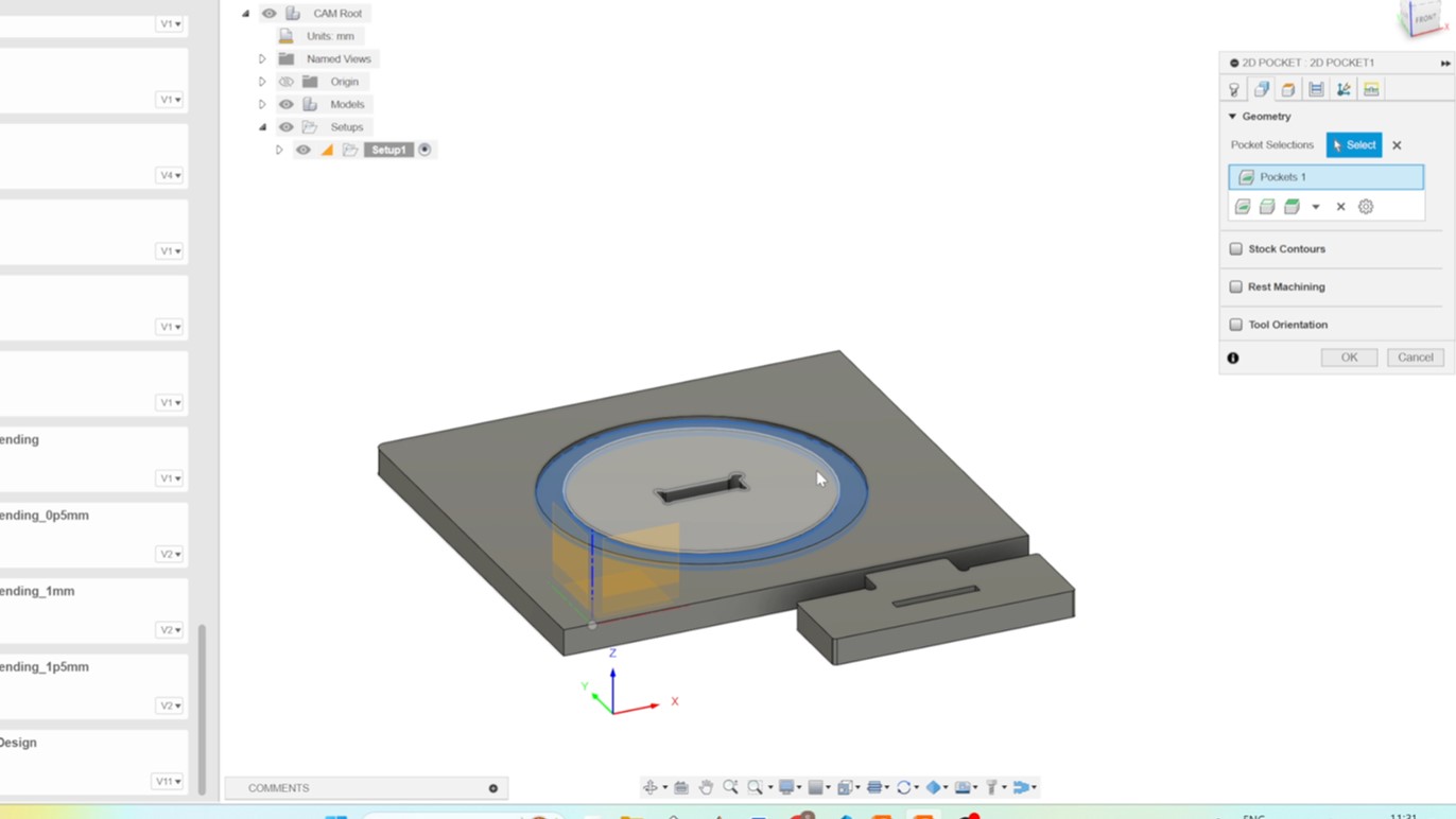
Go to the tab "Geometry" Tab and click on the face you want to create a pocket out of.
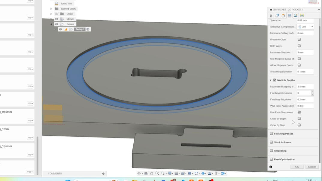
Navigate to the 'Passes' tab and adjust the tolerance as needed. Enable 'Multiple Depths' and customize the parameters according to your preferences. Reducing the step-down can enhance the cut quality and extend the tool's lifespan. After choosing the right parameters for your cut, you click on "OK".
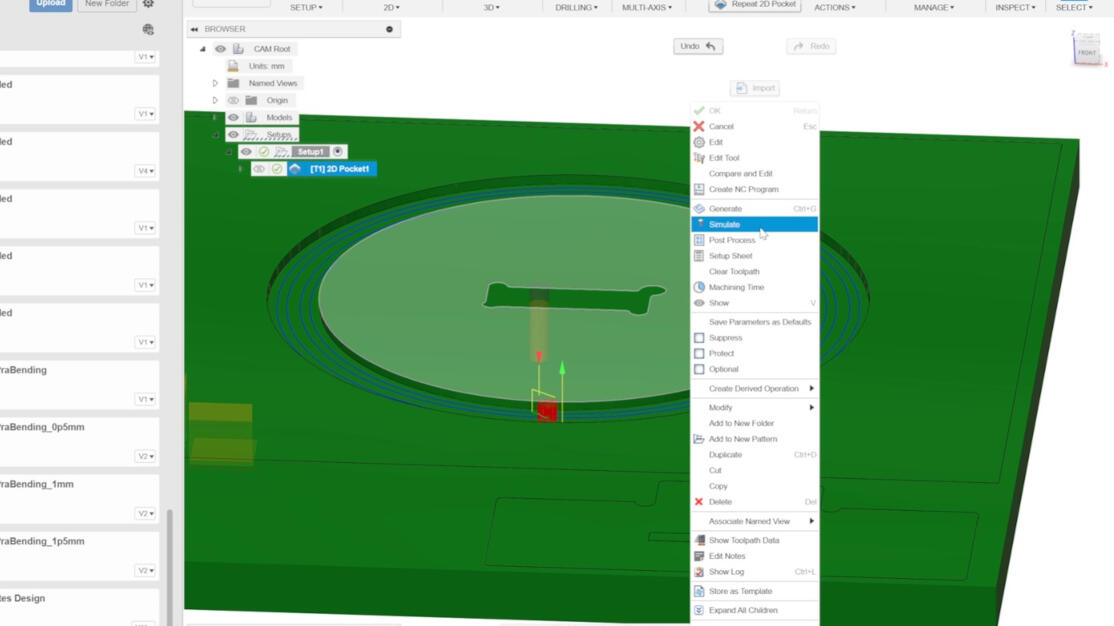
To check, if the cut works out in theory, you can open the Simulation by going "right click" to "Simulation".
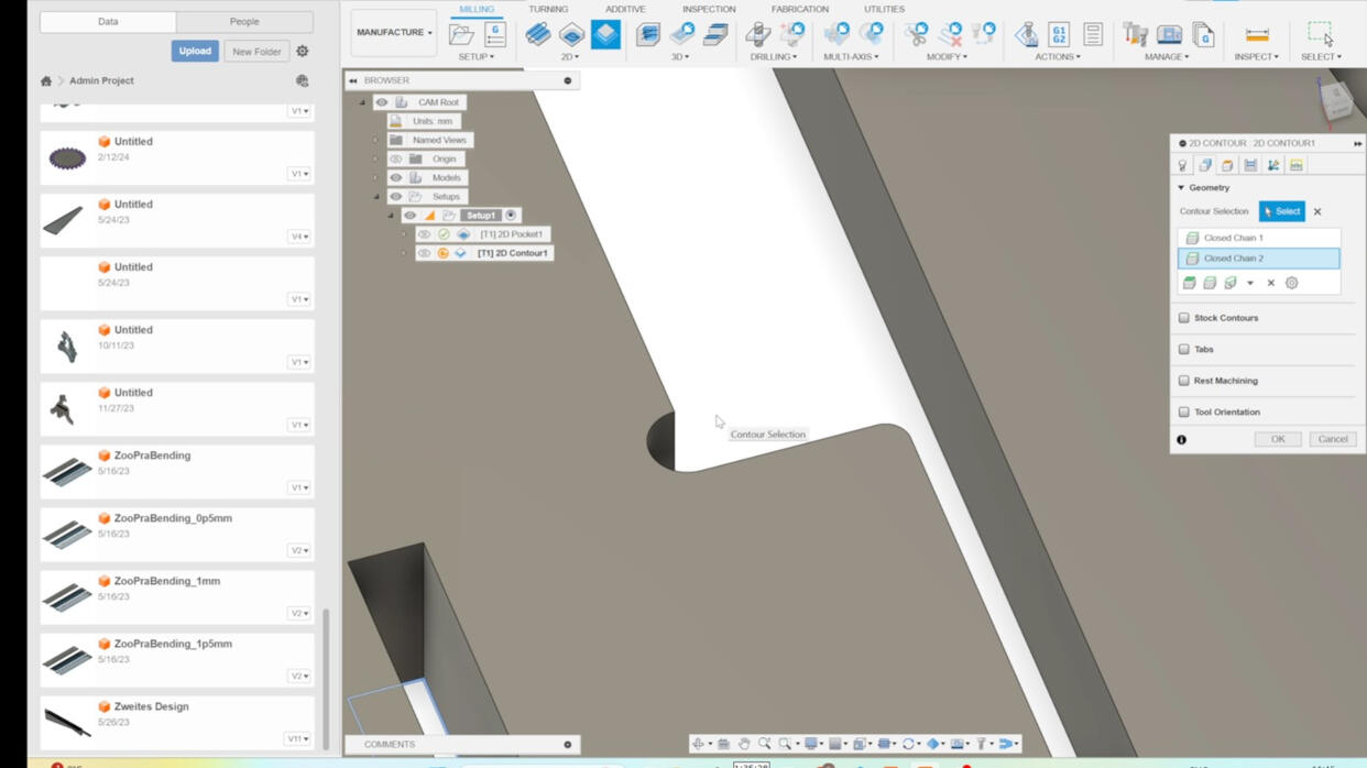
The next step was to create th cut through that are no cutouts of a whole object. To start you go to "2D" and click on "2D Contour". Choose the faces you want to contour. I just created a contour that has the width of the tool to test runout.
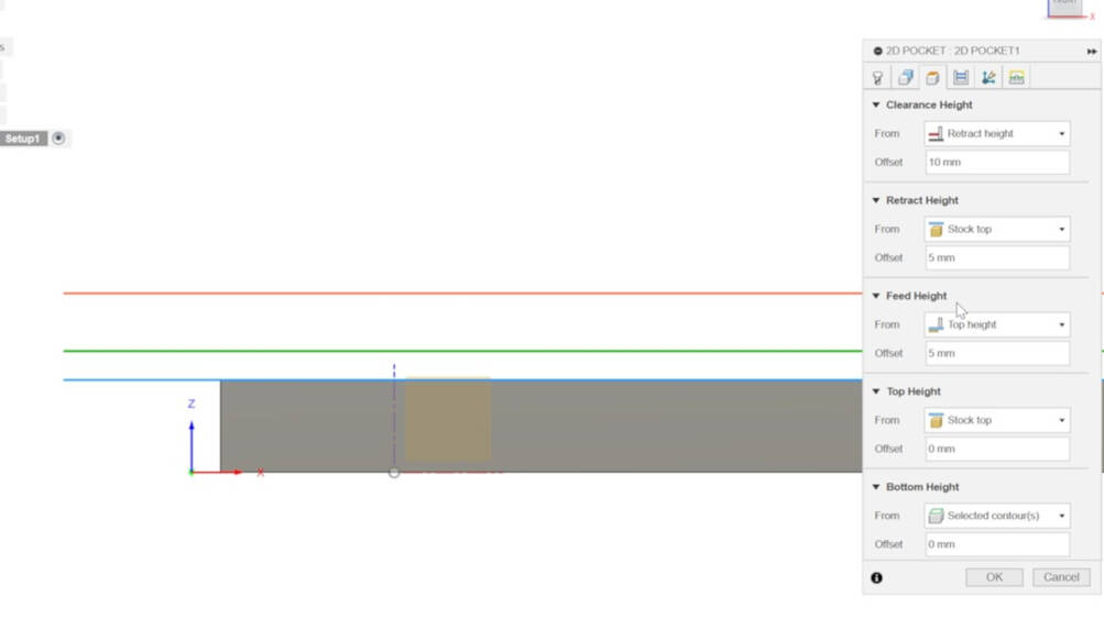
Navigate to the "Heights" tab and select "Bottom Height." Set the distance as "relative to contour" to -0.1 mm to ensure a precise cutout
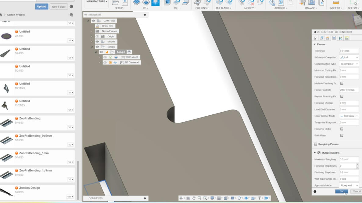
Check if "Multiple Depths" is activated and then click on "OK".
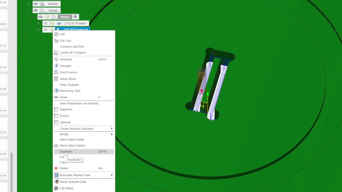
After that you can duplicate the last created setup by "right click" on it and select "duplicate".
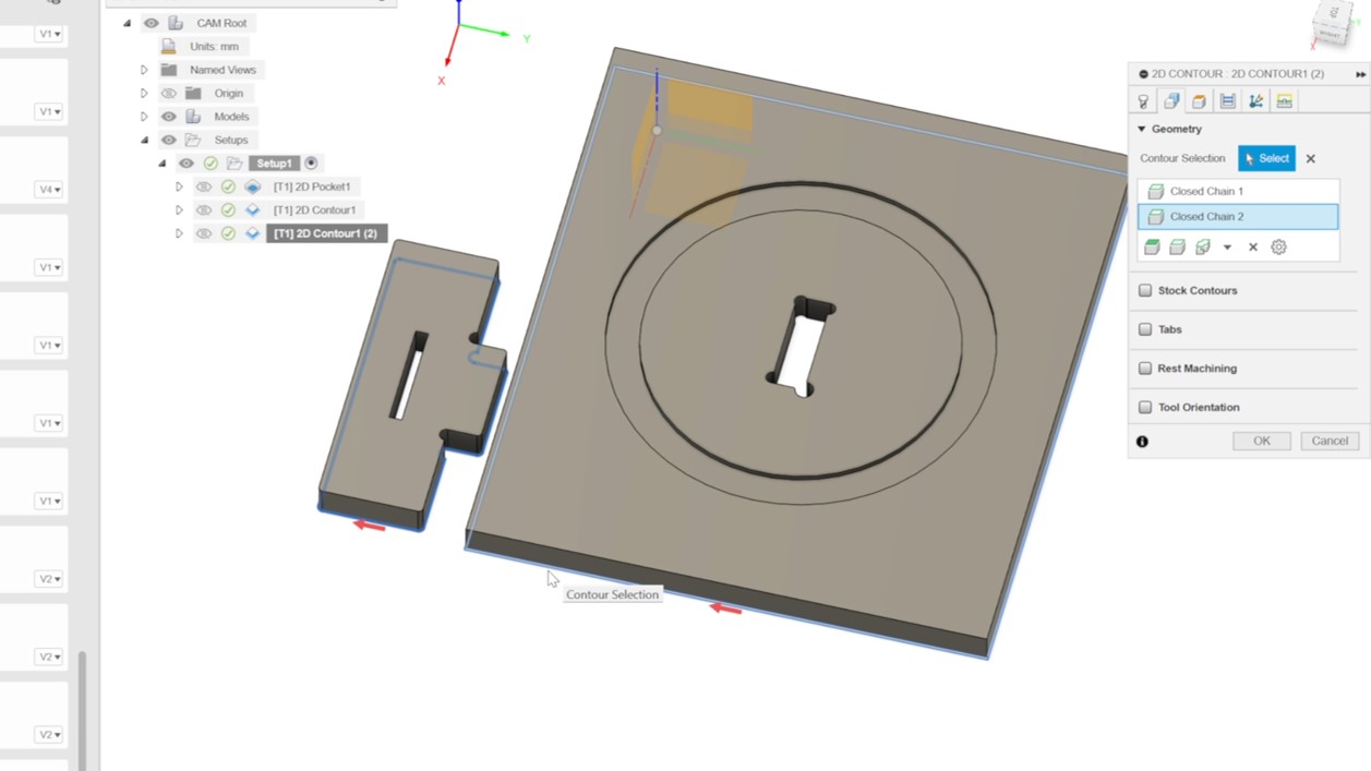
Open the duplicated job and choose a different contours for the final cutout.
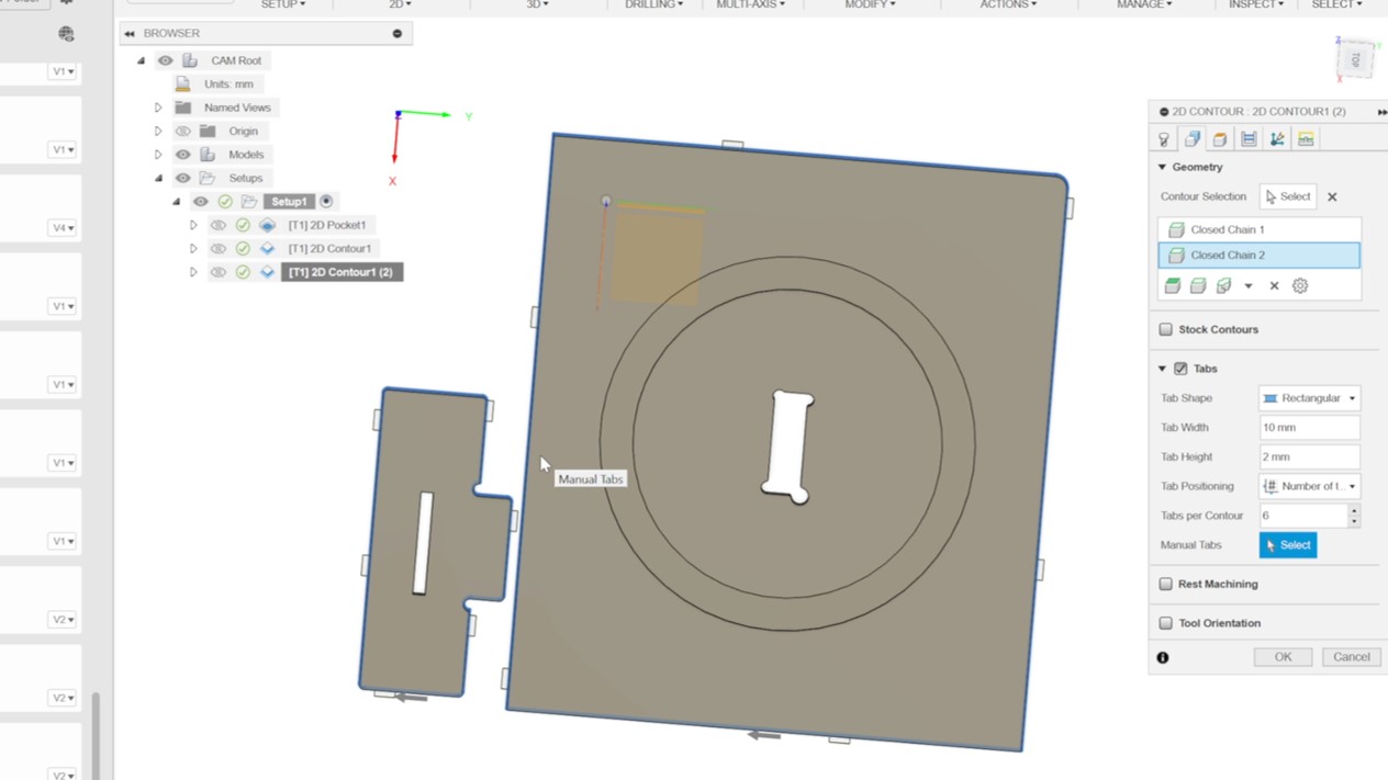
Activate tabs to secure the workpiece. Design the tabs so that they are strategically placed along the contour, avoiding corners. If needed, manually position them next to straight lines of the contour for optimal results.
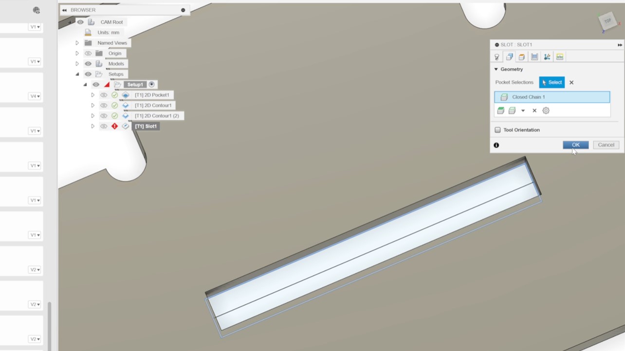
The final step involves creating a slot to test for runout. Click on '2D' and choose 'Slot.' Next, select the contour or line of the slot. Double-check to ensure that 'Multiple Depths' is activated and then click 'OK' to proceed.
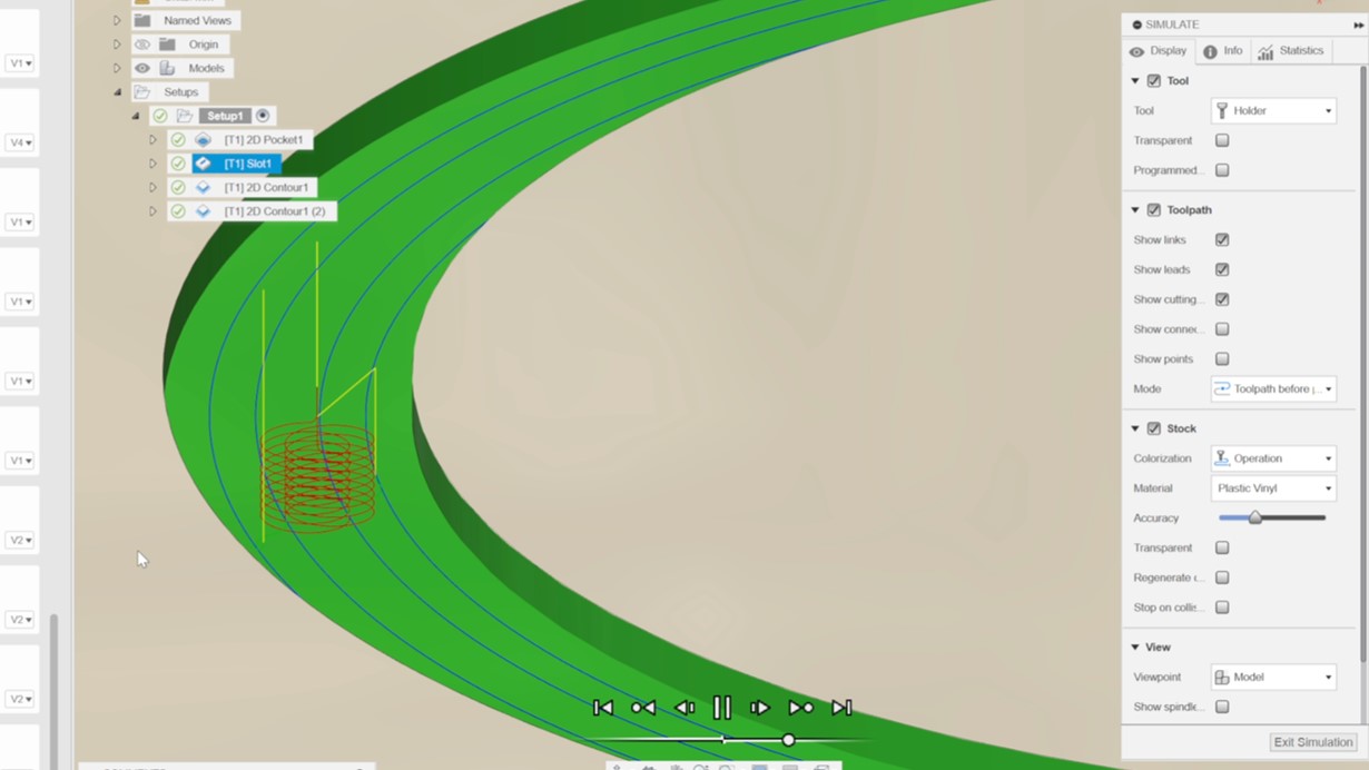
To ensure that each setup adheres to the intended settings, navigate to the simulation tab and carefully review the tool path for any errors. Furthermore, you have the option to rearrange the order of setups by simply dragging and dropping them on the right side of the window for better organization.
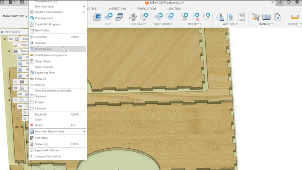
Once you have verified that the simulation yields the intended outcome, proceed to create the post-processing file. Simply right-click on the "Setup" located on the right side of the window and select "Post Processing".
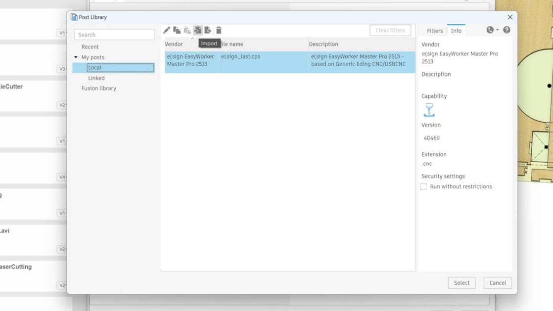
Click on the "folder" icon next to "post" . In the new window, select "Local", then click on "Import" at the top. Choose the required file (depending on your machine) and click "Select".
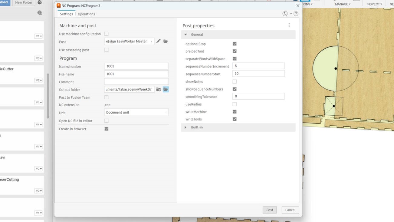
Navigate to the output 'folder' icon, choose your desired destination, and then click 'Post' to create the post precessing file.
Individual Assignment
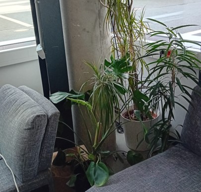
For this week's assignment, our task is to create something BIG, such as a piece of furniture. After contemplating various options, I've chosen to enhance the aesthetics and functionality of a neglected corner in our lab by constructing a custom desk.
This project not only aligns with the assignment's objectives but also fulfills a personal desire to improve our workspace.
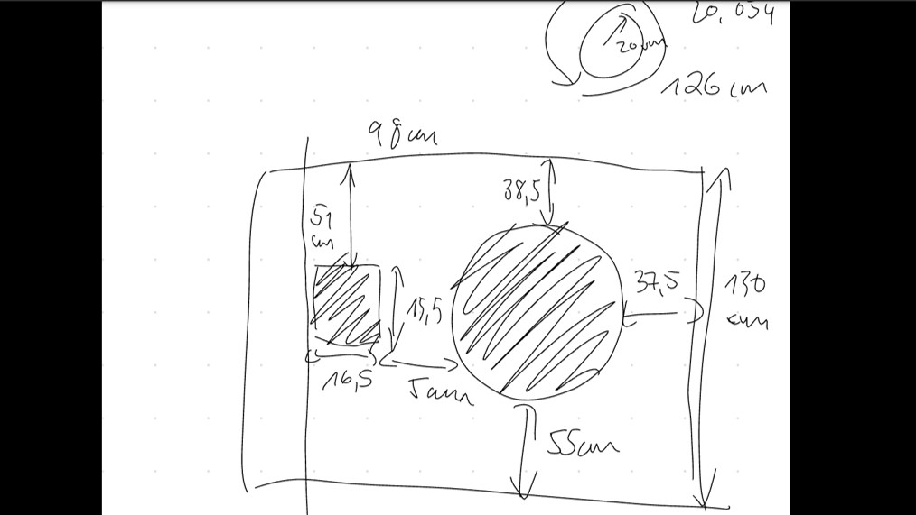
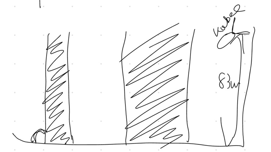
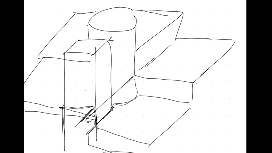
As evident, the desk design must be tailored to fit snugly within the corner, considering the presence of two columns and the confined space between two sofas. To kick off the project, I began by meticulously measuring the dimensions of the corner to ensure precise adaptation of the desk to the available space.
Design in Fusion 360
In the group assignment we used a piece of plywood with a thickness of 12 mm, which in the end was 12.5 mm thick. What should I use now? I could not decide which thickness I will use for my model, so I decided to create a parametric model... NOTE: That was a bad decision, I do not recommend!
I give a brief overview over the designing process. For more detailed steps and description about using Fusion 360 for such a design look into week 2 and week 3.
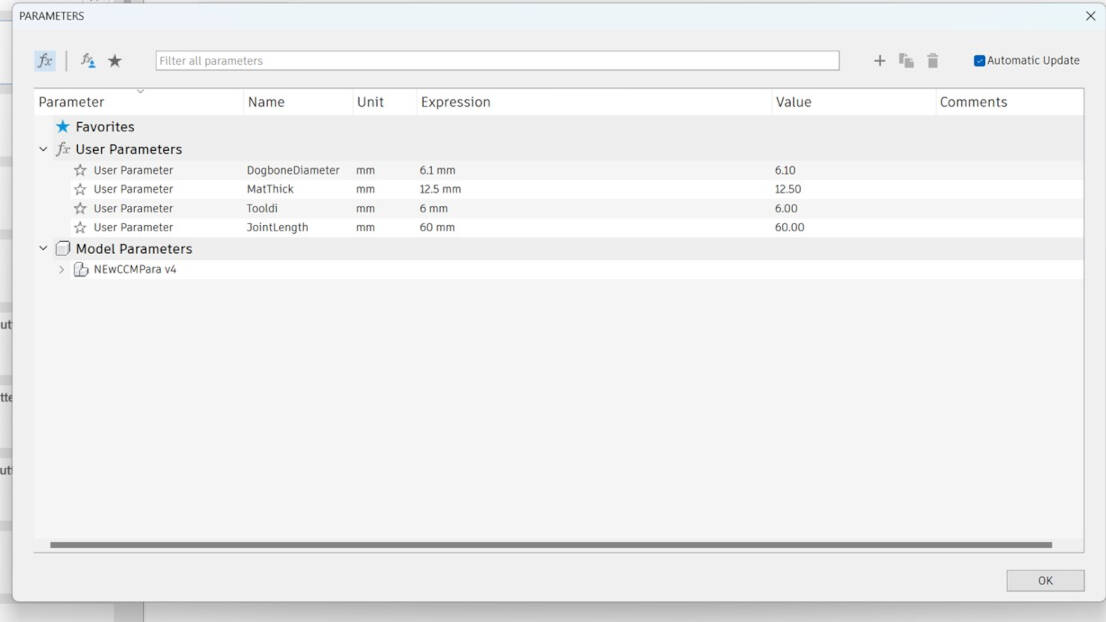
To start with the parametric design, some user parameters were declared. For this design the joint-length defined the length of the finger joints, the dogbone diameter was necessary to make sure the parts fit into each other (tolerance of 0.1 mm), mat_thickness was the material thickness.
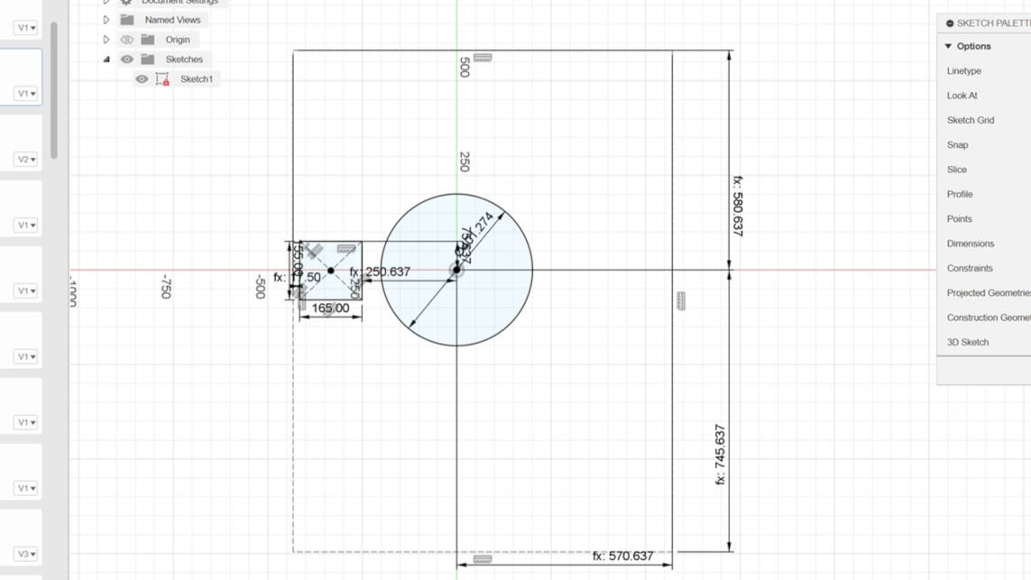
I then created a sketch from the measurement I took. Thereafter I started to create the top parts of the desk and splitted the top into three pieces.
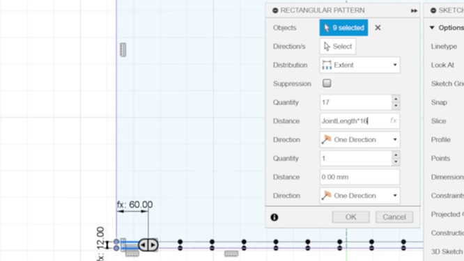
I created the joint for every piece by sketching a rectangle with the joint length and the material thickness. To clone the joints I used the rectangular pattern function. Click on "Create" and go to "rectangular pattern".
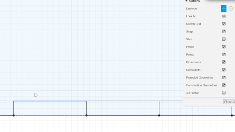
To not destroy the measurement and constrains created ba cloning th rectangular, I marked lines I did not need as construction line. Therefore, select the line and click on "X".
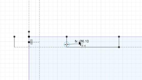
Then, I created the dog bones on the joints and cloned them with the rectangular patter function.
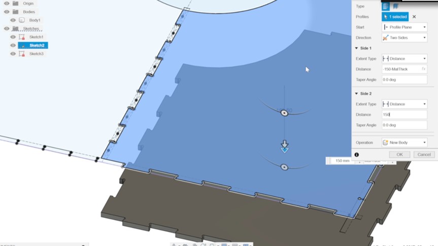
I then extruded the three top plates to the material thickness, as they arranged to each other in an offset of 15 cm, Used the two-sided function of the extrusion to create the offset.
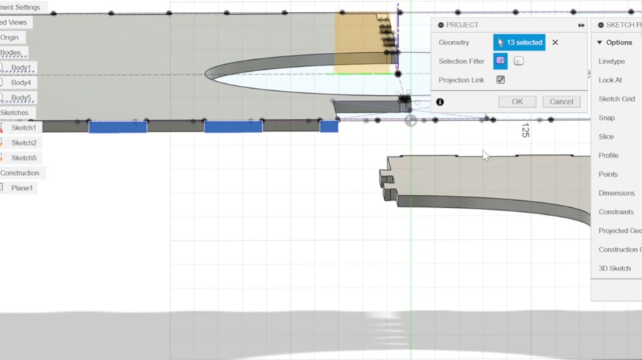
For sketching the side pieces it is crucial to know, where the finger joints of the adjacent pieces are. Therefore, I projected the finger joint connecting the pieces with the projection function. Click on "Create", go to "Project/Include" and choose "Project" (or press P).
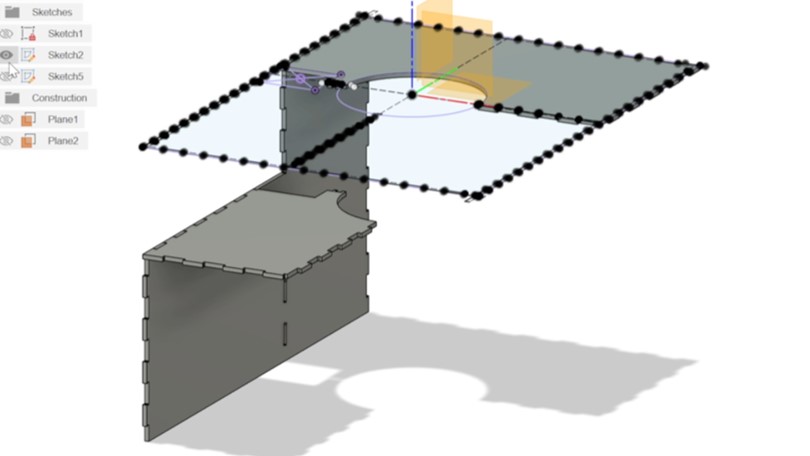
After the finishing a sketch of a piece, I checked for the parametric design. I changed the dog bone diameter and the material thickness in small ranged of 2-4 mm to see if the sketches and the extrusion creates a warning or not. If not I would go on the the next piece.
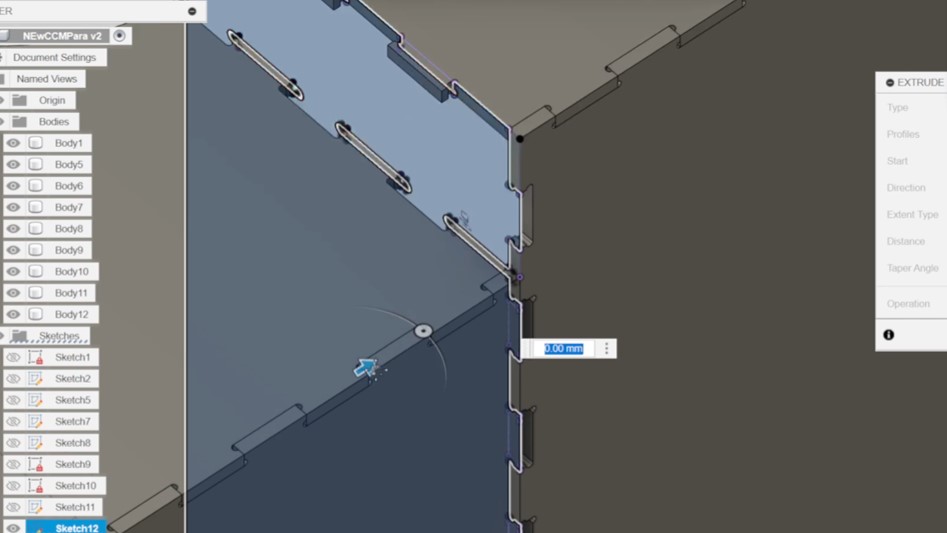
For better support and to cover the offset between the top pieces I created pieces inside of the desk.
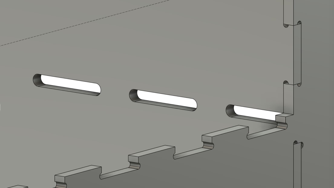
As I had to think about the assembly around the pillar and the corner, I knew that the last top piece had to rotate into one of the side pieces. Therefore, I had to change the joints for this piece.
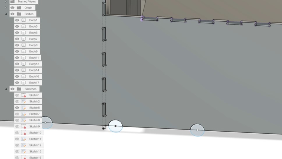
I added holes for cable management on the ground
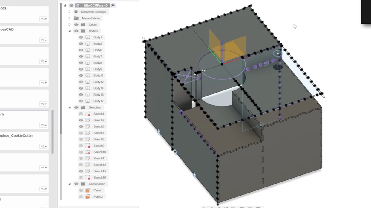
As last step, i checked for mistakes in the design and if the assembly really works out like this.
I rendered the design in Fusion 360.
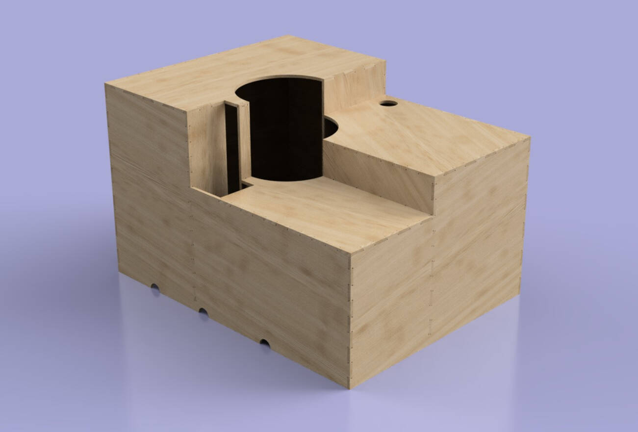
CAM
To start with CAM I had to lay down all the pieces flat and try to put them a closer and tide together as possible (Nesting). I used the "Move/Copy" (press M) to lay all the parts flat. There are to functions in Fusion that are very helpful to create a sufficient nesting.
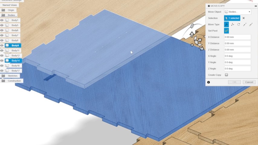
The first one is using the function to set a pivot to snap a body's edge to another body's edge. Click on the pivot symbol in the left window. Select a point on the body you want to move, verify the point by clicking on the pivot symbol again. Drag the body in the direction you want it to move. Than you can align the pivot to another edge or face so it snaps to another body. This makes it easier to keep a exact distance of toll diameter + tolerance from each body.
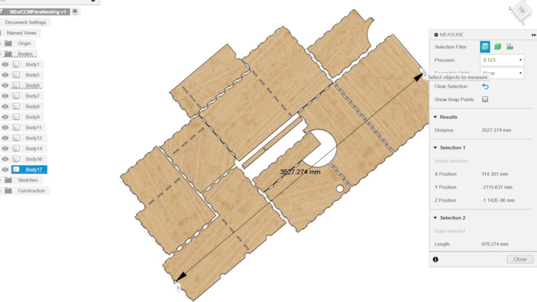
The second function is to measure the overall length of you nesting, to be certain that it fits on your sheet of wood or the machines bed. To do that press "I" to inspect the length and click on to edges that are parallel to each other in the nesting design.
After realizing the dimensions of my design exceeded the capacity of one sheet of wood, and possibly even two, I embarked on a thorough revision process. My goal was to minimize material usage while still accommodating my design within one and a half sheets. Fortunately, my fab mate Frauke graciously offered half of her sheet for my project.
Initially, I began by eliminating substantial sections of the side pieces that abut the walls of the corner. Additionally, I pared down the material of the support pieces. Despite these adjustments, the design still couldn't fit within the available space. Consequently, I had to reduce the desk's size by 12 cm in one direction and even resorted to cutting some pieces in two half to optimize the layout and fit them onto the sheets.
Than I followed the steps of the CAM process described in the group assignment and here for the test pieces. As the tolerance of the joints was not big enough for the test piece. I added a tolerance by enabling "Stock to Leave" in the "Passes" tab and enter 0.25 for both radial and axial stock to leave.
Cutting the Design
For the cuts one and a half multiplex boards of 2500 x 1500 x 12,55 mm (LxWxT) where used.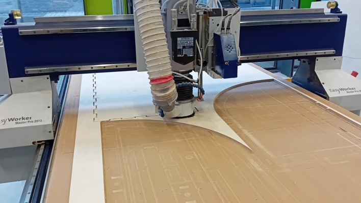
I initially worked with my instructor on the piece of wood remaining from a previous job, which were on a half board.
These cuts proceeded smoothly, even tough the space and nesting was pretty tight.
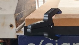
The following day, we proceeded with a single sheet of wood. We secured the wood to the machine using two clamps, which proved to be adequate given the additional support provided by the machine's vacuum fixture.
Following that, we initiated the computer and launched the software. Our initial task involved establishing the cutting origin. Therefore the machine needs to pic up the tool used for the milling job. This can be done within the software:

Go to the "User Menu" (press F11)
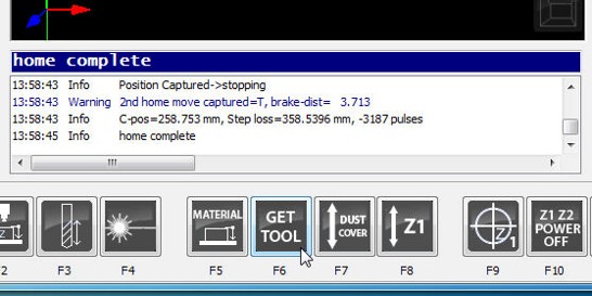
Click on "GET TOOL" ( press F9)
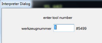
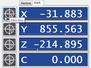
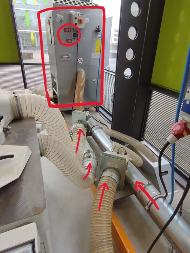
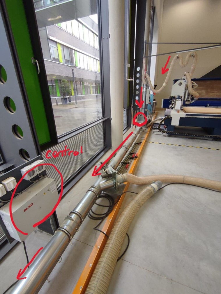
The next step is to start the extraction system. To initiate the setup process, begin by activating the valves using the control switches and ensuring the extraction module is powered on. The control panel houses four switches, each corresponding to a valve from left to right. Therefore, in the absence of any other machine operation, it's imperative to deactivate the three leftmost switches while activating the rightmost one. Concurrently, engage the extraction module by flipping the square switch labeled with red "OFF" and "ON" signs into the "ON" position. This sequence ensures proper valve alignment and activation of the extraction system, facilitating an efficient and safe operational environment.
Thereafter, the cut can be proceeded. Before starting the cut make sure:
- The fixture is sufficient
- The vacuum is on
- The extraction system is on and the valve open
- The axis are zeroed
- You have your safety goggles and ear protection on
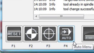
Go "Auto" (press F4)
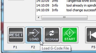
Go to "Load" (press F2) and choose your CAM file.
Thereafter, press "Start" (press F4) and the machine will start to cut your design.
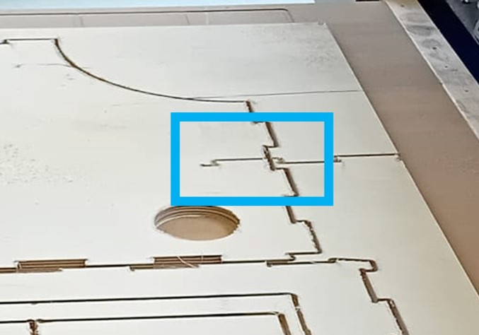
Upon investigation, it was discovered that the Fusion post-processing file had somehow become corrupted. The root cause of the issue was the absence of a WCS (Work Coordinate System) offset, this caused a wrong coordinate system in the setup. To rectify this, we adjusted the WCS offset to 1 by accessing the "Post Processing" tab within the "Edit Setup" menu. This adjustment resolved the immediate problem. Unfortunately, the damage was already done: a big unpleasant cut on one of my pieces!
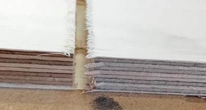
After the machine experienced a shutdown, it created a new, mostly random zero point, leading to a loss of reference. In response, my instructor took a methodical approach by cautiously running the job for the inside contours at a slow pace. By carefully measuring the offset from the original cut, my instructor identified the discrepancy and manually compensated for it by establishing a new zero point.
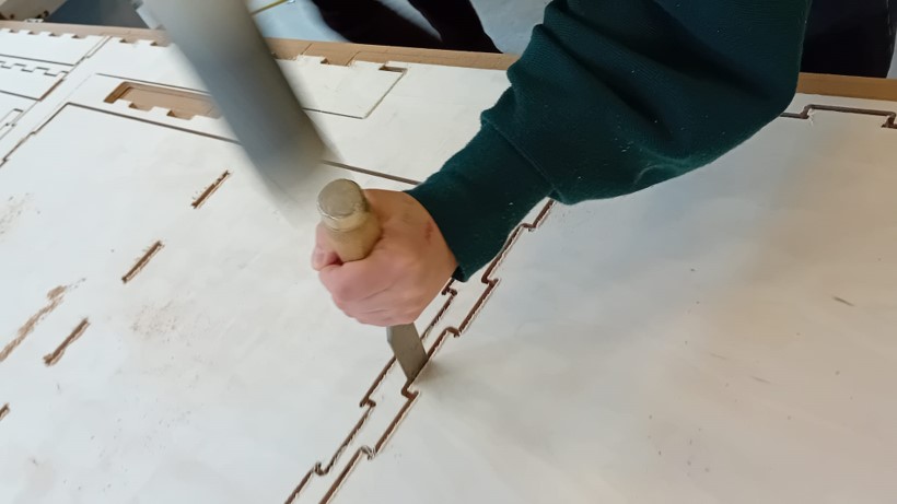
After re-establishing the zero point, the machine commenced cutting the outlines of the design. Initially, the process proceeded smoothly and accurately. However, a challenge emerged due to the bed not being perfectly straight. Consequently, the machine failed to cut through one corner of the bed entirely. Therefore, I manually separated the pieces with a chisel and a hammer.
Thereafter, I had to separate the tabs from the desk pieces.
Post Processing the Cut

To address the unintended cut created by the machine, I applied a blend of sawdust and wood glue to fill the gap. After thoroughly inserting the mixture into the affected area, I allowed it to set for 24 hours. This method effectively restored the integrity of the material, seamlessly concealing the unwanted cut and ensuring a uniform surface.
Afterward, I employed sandpaper, rasps, and a detailed sander to smooth the surface and remove any protruding wood fibers. This meticulous approach ensured a refined finish, enhancing both the appearance and texture of the material.

Even tough, I filled the failed cutting attempt and sanded it, it still was not aesthetically pleasing, as you were able to tell were the gap was filled. Therefore, I decided to paint the one top piece with the cut orange. I used an acrylic color I mixed half a year ago for another project.
Assembly
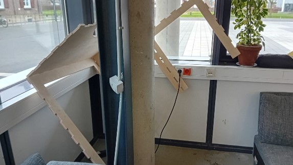
Back Assembly

Front Assembly
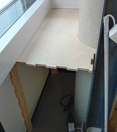
While one piece was drying, I commenced the assembly of the desk, a task that proved to be quite challenging. Employing a hammer, I diligently worked to join the various components together. Initially, I had envisioned assembling the desk in two partial segments. However, upon attempting to position the back assembly with the large top piece in the designated corner, I encountered difficulties, and the anticipated method did not yield the desired outcome.
Subsequently, I disassembled the components and recalibrated my approach. This time, I began by positioning the large top piece in its designated location, ensuring proper alignment. Next, I inserted the side pieces beneath the top piece and carefully pressed the top piece onto the two side components, effectively securing them together.With the aid of a hammer, a few moments of frustration, and tears, I successfully positioned the corner assembly in its designated location. The subsequent task was to install the piece adjacent to the steel beam, further advancing the assembly process.
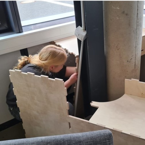
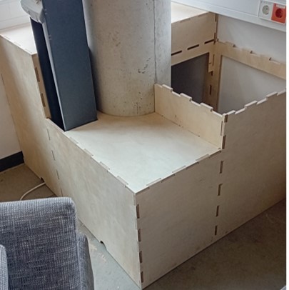
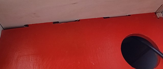
The final piece, painted in orange, required additional time to dry, so I inserted it into place a few days later. However, during assembly, I encountered a minor issue: one of the inner pieces failed to bend away from its intended position, making it difficult to achieve a perfect fit. Unfortunately, I couldn't reach inside the desk to rectify the situation, which would have been necessary for ideal placement.
Here is the finished assembly:


Reflection
Group Assignment
During our group assignment, we conducted our initial tests to assess runout, alignment, fixturing, speeds, feeds, and toolpaths. We underwent safety training and learned to operate the machine. However, we were closely supervised by our instructor during each cut setup and operation, which was necessary considering the time and experience required to work on the machine independently.
Despite our familiarity with the machine, we encountered challenges achieving the desired tolerance for the cuts to fit the joint together. Surprisingly, the precision was relatively low (maybe due to the material and settings we were using), leading us to increase the tolerance (or stock to leave) to -0.5 mm, which, in my opinion, is significant. In general, the "stock to leave" option is used for leaving the possibility to work with a finishing cut or to sand it off. Stock to leave is the amount of material that must remain on the part after machining. Be aware that also other settings influence the value tolerance and therefore the fit, e.g. add tolerance/offset to your cut.
Another observation was the dependence of cut accuracy and splintering on the direction of wood fibers. The level of splintering was higher than expected, especially compared to references like Roland Grichnik's work. Possible reasons for this could include the type of wood used, the choice of cutting tool (such as up-cutting) or a blunt tool, and the feed rate.
To improve the situation, we can consider:
- Choosing wood types that are less prone to splintering.
- Selecting appropriate cutting tools, such as down-cutting router bits and a sharper tool
- Controlling cutting direction to minimize splintering.
- Conducting test cuts and iterating on settings to find the best parameters for our specific materials and requirements.
Individual Assignment
During my individual assignment, I encountered several challenges. Firstly, I initially pursued a design that turned out to be excessively large and complex. In hindsight, opting for a more minimalist approach would have been wiser.
The second challenge arose during assembly. I discovered a tolerance of 0.5 cm on each side of the desk, that I included in the design, was not enough to encounter for the uneven floor in the lab. Therefore, the height of the table conflicted with the placement of the cable management box. This significantly complicated the assembly process, as I couldn't insert the first few pieces from the top.
Lastly, post-processing proved to be time-consuming. It took several days because I needed the paint to dry before applying the coating. This wouldn't have been as daunting if not for the issues with the machine.
Overall, I found the entire process to be incredibly draining and frustrating. Additionally, I was the first week, where I really fell behind.
Download and Files
- Desk (Fusion File): download