WEEK 12
Networking and Communications
Group Assignment:
- Send a message between two projects.
Individual Assignment:
- Design, build and connect wired or wireless node(s) with network or bus addresses and a local interface
1.Overview
To complete this week's assignment, I used the RP2040-Zero microcontroller to send data to my two pre-designed boards and switch their LEDs on and off.
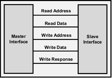
2.What is Master/Slave Communication
In the circuit I designed, RP2040-Zero is called master and the boards I designed before are called slave. But what do master and slave mean in communication language?
Typically a master sends out requests or instructions and a slave responds to them. In other words in a master/slave communication system the master controls the communication. Slaves only "talk" in response to commands from the master. The master/slave model can be used when multiple devices, processes, or applications share the same resources. For example, this model is applicable when transmitting data via a data bus. It regulates requests and ensures that communication between signals occurs without interference or modification from other participants, guaranteeing that all processes are executed correctly.
3. In what common scenarios is the master/slave model used?
- Regulate and coordinate bus systems for information exchange: The master manages and directs the secondary devices, ensuring that the data bus accurately receives and processes information.
- Organize resources within a computer network: The master allocates network resources based on a specific logic, ensuring all participants can perform their tasks efficiently.
- Create a piconet of terminals using Bluetooth: The master/slave model is employed to establish piconets, a type of personal area network that connects end devices via Bluetooth.
4. Circuit Design
You can see how the circuit is connected in the image below.
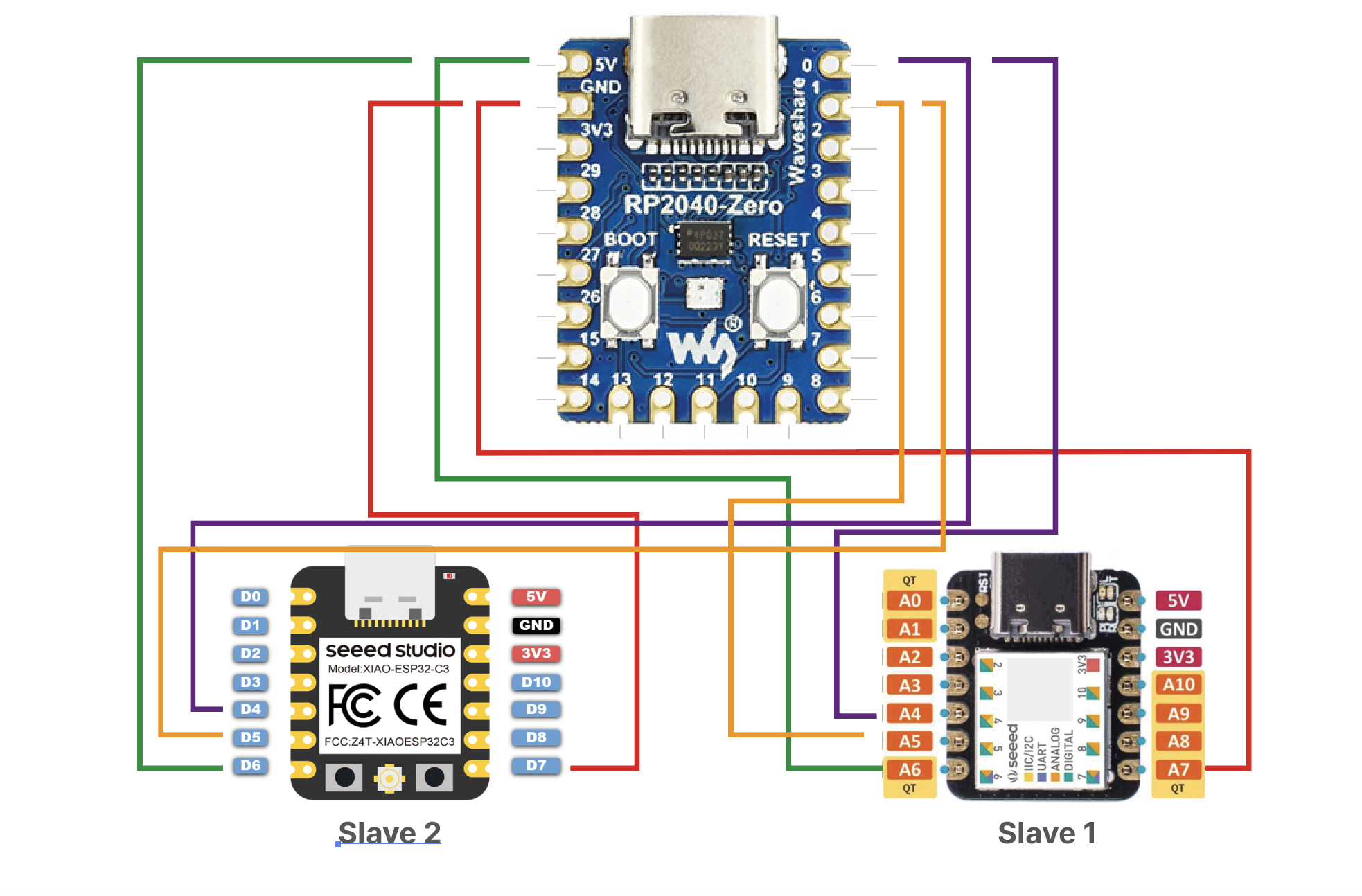
| Component Name | Purpose of Having |
|---|---|
| RP2040-Zero | Microcontroller- Master |
| Board Design with Seeeduino XIAO SAMD21 | Slave 1 |
| Board Design with Seeeduino XIAO ESP32-C3 | Slave 2 |
You can find my board designs here. - Slave 1
You can find my board designs here. - Slave 2
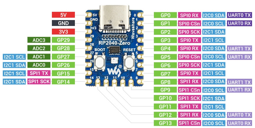
RP2040-Zero
The RP2040-Zero, is a low-cost, high-performance Pico-like MCU board based on Raspberry Pi RP2040 microcontroller. I used the pin out schematic of the RP2040-Zero when making my circuit design.
5. Programming
We started programming with RP2040-Zero. At first I decided to use the library called RF24-master for this. But then I realised that this library is compatible with the old version of the microcontroller and is not compatible with the microcontroller because it has not been updated. For this reason, I started working based on Sophia Doring's code. Here you can find.
My code for the master is as follows;
// Wire Master Writer
// by Nicholas Zambetti

// Demonstrates use of the Wire library
// Writes data to an I2C/TWI slave device
// Refer to the "Wire Slave Receiver" example for use with this

// Created 29 March 2006

// This example code is in the public domain.


#include  // This includes the Wire library, which is used for I2C communication.
int addressI2C =0; // This variable will store the I2C address received from the Serial input.

void setup()
{ Wire.setSDA(0);
Wire.setSCL(1);
Wire.begin(); // This initializes the I2C bus as a master.
Serial.begin(9600); // This starts the Serial communication at a baud rate of 9600, allowing communication between the RP2040-Zero and a computer.
}

byte x = 0;

void loop()
{
if (Serial.available()) {      // If there is data available on the Serial interface, it reads an integer from the Serial input and stores it in addressI2C. The received address is printed back to the Serial monitor.
addressI2C=Serial.parseInt();   // read it and send it out Serial1 (pins 0 & 1)
Serial.println(addressI2C);
}

// Depending on the value of addressI2C, different messages are sent to the slave devices with addresses 4 and 5.
if (addressI2C==4) {
Wire.beginTransmission(4); // transmit to device #4
Wire.write(1);              // sends one byte
Wire.endTransmission();    // stop transmitting
delay(50);
Wire.beginTransmission(5); // transmit to device #4
Wire.write(0);              // sends one byte
Wire.endTransmission();    // stop transmitting

}else if (addressI2C==5) {
Wire.beginTransmission(5); // transmit to device #4
Wire.write(1);              // sends one byte
Wire.endTransmission();    // stop transmitting
delay(50);
Wire.beginTransmission(4); // transmit to device #4
Wire.write(0);              // sends one byte
Wire.endTransmission();    // stop transmitting
}
else if (addressI2C==9){
Wire.beginTransmission(5); // transmit to device #4
Wire.write(1);              // sends one byte
Wire.endTransmission();    // stop transmitting
delay(50);
Wire.beginTransmission(4); // transmit to device #4
Wire.write(1);              // sends one byte
Wire.endTransmission();    // stop transmitting
}else{
Wire.beginTransmission(5); // transmit to device #4
Wire.write(0);              // sends one byte
Wire.endTransmission();    // stop transmitting
delay(50);
Wire.beginTransmission(4); // transmit to device #4
Wire.write(0);              // sends one byte
Wire.endTransmission();    // stop transmitting
}

delay(100); // Adds a delay of 100 milliseconds before repeating the loop.
}
Explanation of the code;
- This code sets up an RP2040-Zero as an I2C master device that communicates with two I2C slave devices (at addresses 4 and 5). Based on the input received over the Serial interface, the master sends specific byte values to the slave devices to control them accordingly.
- For addressI2C == 4: Sends the byte 1 to the slave device at address 4. Sends the byte 0 to the slave device at address 5.
- For addressI2C == 5: Sends the byte 1 to the slave device at address 5. Sends the byte 0 to the slave device at address 4.
- For addressI2C == 9: Sends the byte 1 to both slave devices at addresses 4 and 5.
- For any other addressI2C value: Sends the byte 0 to both slave devices at addresses 4 and 5.
My code for the Slave 1 is as follows;
// Wire Slave Receiver
// by Nicholas Zambetti

// Demonstrates use of the Wire library
// Receives data as an I2C/TWI slave device
// Refer to the "Wire Master Writer" example for use with this

// Created 29 March 2006

// This example code is in the public domain.


#include
int x = 0;

void setup()
{
Wire.begin(5);                // join i2c bus with address #4
Wire.onReceive(receiveEvent); // register event
Serial.begin(9600);           // start serial for output

pinMode(8,OUTPUT);
}

void loop()
{
delay(100);
if(x==1){

digitalWrite(8,HIGH);


}else{  digitalWrite(8,LOW);


}}

// function that executes whenever data is received from master
// this function is registered as an event, see setup()
void receiveEvent(int howMany)
{
while(1 < Wire.available()) // loop through all but the last
{
char c = Wire.read(); // receive byte as a character
Serial.print(c);         // print the character
}
x = Wire.read();    // receive byte as an integer
Serial.println(x);         // print the integer
}
This code sets an RP2040-Zero as an I2C slave device with 5 addresses. It listens for data from the I2C master and checks the output state of pin 8 depending on the data received. In my circuit, it controls the LED at the output of pin 8. If the last byte received is a 1, pin 8 is set HIGH and the LED is on; otherwise it is set LOW and the LED is off.
- Wire.begin(5) --- This initializes the I2C bus as a slave with address 5.
- Serial.begin(9600) --- This starts the Serial communication at a baud rate of 9600, allowing communication between the RP2040-Zero and a computer.
- pinMode(8, OUTPUT) --- This sets pin 8 as an output pin.
- if(x == 1) { digitalWrite(8, HIGH); } else { digitalWrite(8, LOW); } --- If the value of x is 1, it sets pin 8 to HIGH, otherwise, it sets pin 8 to LOW. This controls the output state of pin 8 based on the received data.
My code for the Slave 2 is as follows;
// Wire Slave Receiver
// by Nicholas Zambetti

// Demonstrates use of the Wire library
// Receives data as an I2C/TWI slave device
// Refer to the "Wire Master Writer" example for use with this

// Created 29 March 2006

// This example code is in the public domain.


#include

void setup()
{
Wire.begin(5);                // join i2c bus with address #4
Wire.onReceive(receiveEvent); // register event
Serial.begin(9600);           // start serial for output
}

void loop()
{
delay(100);
}

// function that executes whenever data is received from master
// this function is registered as an event, see setup()
void receiveEvent(int howMany)
{
while(1 < Wire.available()) // loop through all but the last
{
char c = Wire.read(); // receive byte as a character
Serial.print(c);         // print the character
}
int x = Wire.read();    // receive byte as an integer
Serial.println(x);         // print the integer
}
- Wire.begin(5) --- This initializes the I2C bus as a slave with address 5.
- Serial.begin(9600) --- This starts the Serial communication at a baud rate of 9600, allowing communication between the RP2040-Zero and a computer.
6. Testing
We have enabled the master to control the slaves via the serial monitor.
- We have enabled the master to control the slaves via the serial monitor.
- Number 4 turns on one slave.
- Number 5 turns on other slave.
- Number 0 turns of everything.
- Number 9 turns on both slave.