Networking and Communication
design, build, and connect wired or wireless node(s) with network or bus addresses and local input &/or output device(s)Assignments
- Group Assignment
- send a message between two projects
- Individual Assignment
- design, build, and connect wired or wireless node(s) with network or bus addresses and local input &/or output device(s)
Hero Shot
Communication Protocols
UART (Universal Asynchronous Receiver-Transmitter)
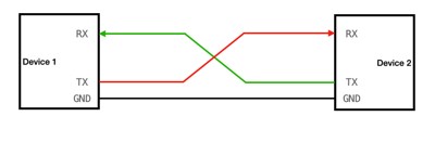
UART represents a fundamental serial communication protocol widely integrated into electronic systems. It facilitates the exchange of data between devices via dedicated transmit (TX) and receive (RX) lines.
The term "asynchronous" denotes a characteristic of UART signaling wherein data transmission occurs without the dependency on a shared clock signal between sender and receiver. Instead, communication is synchronized by establishing a predefined baud rate, agreed upon by both devices, dictating the rate at which data bits are transmitted and received.
UART's appeal lies in its simplicity and efficiency. Its implementation requires minimal hardware complexity, making it suitable for various applications where straightforward data exchange is required. Common scenarios include interconnection between microcontrollers and peripheral sensors, or between computing devices and peripheral hardware.
I already implemented a communication with UART in week 11 to let the PCb communicate with my computer and show the serial data from the load cell.
I2C (Inter-Integrated Circuit)
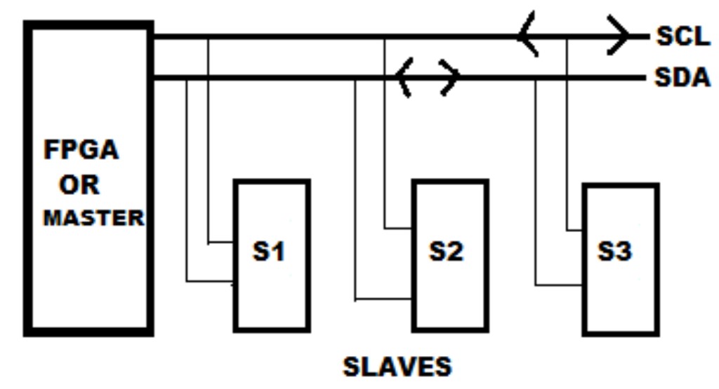
I2C is a communication protocol used for connecting multiple electronic devices together. It's a simple and efficient way for these devices to exchange data and commands.
In an I2C setup, devices are connected using two wires: a clock line (SCL) and a data line (SDA). The clock line controls the timing of data transmission, while the data line carries the actual information being sent between devices.
One of the key features of I2C is its ability to support multiple devices on the same bus. Each device has a unique address, allowing them to communicate with each other without interference. This makes I2C ideal for scenarios where several sensors, memory chips, or other peripherals need to be connected to a single microcontroller or other host device.
I2C is widely used in various applications, from simple sensor networks to complex embedded systems.
SPI (Serial Peripheral Interface)
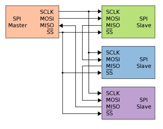
SPI is a way for devices to talk to each other. There are two main parts: the master (which controls everything) and the slave (which follows the master's orders).
They connect with four wires:
- MOSI: Master Out Slave In (for sending data from the master to the slave).
- MISO: Master In Slave Out (for sending data from the slave to the master).
- SCK: Serial Clock (this keeps everything in sync).
- SS/CS: Slave Select/Chip Select (this tells the slave it's time to listen).
When the master wants to send data to a slave, it puts the data on MOSI and sends clock signals on SCK. The slave reads this data from MOSI and responds by putting data on MISO. The master then reads this response.
Both the master and slave need to be set up with the same settings, like how they use the clock and data order, so they can understand each other.
In simple terms, SPI is a simple and fast way for devices to talk to each other, commonly used in things like microcontrollers and sensors.
USB (Universal Serial Bus)
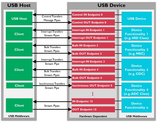
USB is a standard way for devices to connect and communicate with each other.
It uses cables with different connectors like Type-A or Type-C. One device acts as the host, controlling communication, while the other is the peripheral.
USB cables not only transfer data but also provide power to devices, and they come in different versions with varying speeds. USB is known for its plug-and-play feature, allowing devices to be connected without needing to restart or install drivers.
Overall, it's a widely used standard for connecting devices, transferring data, and supplying power.
Wi-Fi (Wireless Fidelity)
Wi-Fi, short for Wireless Fidelity, is a technology that enables devices like smartphones, laptops, and tablets to connect to the internet and communicate with each other without relying on physical cables. It operates by transmitting data through radio waves between devices and Wi-Fi access points, such as routers or hotspots.
To establish a Wi-Fi connection, a device must be within the range of an access point emitting a Wi-Fi signal. Once connected, devices can exchange data and access the internet if the access point is connected to it.
Wi-Fi offers numerous advantages, including convenience, as it allows for flexible device placement and mobility within the coverage area. It also provides high-speed internet access, making it suitable for activities like streaming media and online gaming. Moreover, Wi-Fi is compatible with a wide range of devices, from smartphones to smart home appliances.
However, Wi-Fi also has its limitations. The range of a Wi-Fi network can be limited by physical obstacles like walls or interference from other electronic devices. Additionally, security concerns can arise if the network is not properly secured, potentially leading to unauthorized access or data breaches.
Overall, Wi-Fi has become an integral part of modern life, enabling seamless wireless connectivity in homes, offices, public spaces, and beyond.
Bluetooth
Bluetooth is a wireless communication technology designed for short-range data exchange between electronic devices. It operates via radio frequency signals, enabling devices such as smartphones, headphones, speakers, and smartwatches to establish connections and exchange information without physical cables.
Devices equipped with Bluetooth functionality emit radio waves to detect nearby compatible devices within a limited range. Upon discovery, devices can establish a connection and communicate with each other. Bluetooth connections are characterized by their reliability and relatively high data transfer speeds, making them suitable for various applications such as wireless audio streaming and file sharing.
One notable feature of Bluetooth is its ability to facilitate simultaneous connections between multiple devices. For instance, a smartphone can connect to both a wireless headset for audio playback and a smartwatch for data synchronization concurrently.
Moreover, Bluetooth technology is renowned for its energy efficiency, ensuring minimal power consumption during data transmission. This aspect is particularly advantageous for battery-powered devices like fitness trackers and IoT sensors, allowing for prolonged operational durations between recharges.
Trying I2C (INTER-INTEGRATED CIRCUIT)
Before starting the connection of I2C, Frauke Waßmuth and I, where using I2C for the group assignment.Therefore, the first tests of using I2C can be looked up in the group assignment page.
Schematic Diagram
In the proposed I2C communication circuit, there will be one master microcontroller and two slave microcontrollers. The master microcontroller will receive a signal from an LDR (Light Dependent Resistor), which varies its resistance based on the amount of incident light.
Upon receiving the light intensity data from the LDR, the master microcontroller will transmit this information to the two slave microcontrollers via the I2C bus.
The first slave microcontroller will be programmed to activate an LED when the received light intensity exceeds a predefined threshold, serving as an indicator for high light levels. Conversely, the second slave microcontroller will deactivate an LED under similar conditions, providing a visual cue for low light levels.
The threshold values for activating or deactivating the LEDs can be adjusted based on specific requirements and environmental conditions.
As microcontrollers a Arduino Nano is used as a master. The SAMD21 PCB built in Week 04 and the Attiny 2326 in the PCB built in week 08 will be used as slaves.

Programming
Master Program
The master code is presented below.
#include "Wire.h"

	const int ldrPin = A2;
	int threshhold = 450;
	int status_wire;
	void setup() {
		// put your setup code here, to run once:

	Serial.begin(9600);
	Wire.begin();
	pinMode(ldrPin, INPUT); // Here LDR sensor is determined as input.
	}

	void loop() {
		// put your main code here, to run repeatedly:
	int ldrStatus = analogRead(ldrPin);
	Serial.println(ldrStatus);
	if (ldrStatus > threshhold){
	Wire.beginTransmission(9);
	Wire.write(0);
	int status_wire = Wire.endTransmission();
	Serial.println(status_wire);
		Wire.beginTransmission(12);
	Wire.write(1);
	status_wire = Wire.endTransmission();
	Serial.println(status_wire);
		delay(200);
	}
	if (ldrStatus < threshhold){
	Wire.beginTransmission(9);
	Wire.write(1);
	status_wire = Wire.endTransmission();
	Serial.println(status_wire);
		Wire.beginTransmission(12);
	Wire.write(0);
	status_wire = Wire.endTransmission();
	Serial.println(status_wire);
		delay(200);
	}

	}
- The code begins by including the Wire library for I2C communication.
- It defines two constants:
ldrPin: Specifies the analog pin (A2) to which the LDR (Light Dependent Resistor) is connected.threshold: Sets the threshold value for the light intensity.
- The global variable
status_wireis declared to store the status of I2C transmissions. - In the
setup()function:- Serial communication is initialized at a baud rate of 9600.
- The Wire library is initialized for I2C communication.
- The
ldrPinis set as an input pin to read analog data from the LDR.
- In the
loop()function:- The analog value from the LDR is read and stored in the variable
ldrStatus. - The value of
ldrStatusis printed to the serial monitor. This was first used as a check for a suitable threshold.
- The analog value from the LDR is read and stored in the variable
- If the
ldrStatusis greater than the threshold:- The Arduino initiates an I2C transmission to Slave 1 (address 9) with a value of 0, indicating that an LED should be turned off.
- Another I2C transmission is initiated to Slave 2 (address 12) with a value of 1, indicating that an LED should be turned on.
- The status of each I2C transmission is stored in the variable
status_wire.
- If the
ldrStatusis less than the threshold:- Similar I2C transmissions are performed, but the values sent to the slaves are inverted to control the LEDs accordingly.
Slave Program
The first code is for the SAMD21 slave, as the code was written for the Arduino IDE v. 2.3.2.
#include "Wire.h"
	int LED = 8;
	int x = 0;
	void setup() {
		pinMode(LED, OUTPUT);
		Wire.begin(12);
		Wire.onReceive(receiveEvent);
		Serial.begin(9600);
	}
	void receiveEvent(int bytes) {
		x = Wire.read();    // read one character from the I2C

	}
	void loop() {

		Serial.println(x);

		if (x == 0) {
		digitalWrite(LED, HIGH);
		}
		else{
		digitalWrite(LED, LOW);
		}


	}
The second code is for the attiny 2326 slave. The code needed to be uplaoded with the Arduino IDE v. 1.8.18.
#include "Wire.h"
	int LED = 8;
	int x = 0;
	void setup() {
		pinMode(LED, OUTPUT);
		Wire.begin(9);
		Wire.onReceive(receiveEvent);
		Serial.begin(9600);
	}
	void receiveEvent(int bytes) {
		x = Wire.read();

	}
	void loop() {

		Serial.println(x);

		if (x == 0) {
		digitalWrite(LED, HIGH);
		}
		else{
		digitalWrite(LED, LOW);
		}


	}
- The code begins by including the Wire library for I2C communication.
- Define Variables:
- LED: Specifies the pin connected to the LED (pin 8).
- x:Stores the data received from the master device over I2C.
- Setup Function:
- Configures the LED pin as an output pin.
- Initializes the microcontroller as an I2C slave device with address 12 (or 9 for the first code).
- Attaches a function (
receiveEvent) to be called when data is received over I2C. - Initiates serial communication for debugging purposes at a baud rate of 9600.
- Receive Event Function:
- This function is called whenever data is received over the I2C bus.
- It reads the received data byte by byte from the I2C buffer and stores it in the variable
x.
- Loop Function:
- Prints the value of
xto the serial monitor for debugging. - Checks the value of
x: - If
xis equal to 0, it sets the LED pin HIGH, turning on the LED. - If
xis not equal to 0, it sets the LED pin LOW, turning off the LED.
- Prints the value of
Results
Testing the Threshold
First step was to test a find a good threshold for the functionality.
The the values showed a range of 300 to 650, I decided to use 450 as a threshold.
Testing I2C
I connected the two PCB slaves to the master.
Evaluation
Group Assignment
During our group assignment, we encountered difficulties with I2C communication between two SAMD21 boards (see here) . Despite our initial efforts, the communication was not functional. We conducted thorough troubleshooting to identify the root cause of the issue.
The I2C communication was not working at first. So what is the problem?
Firstly, it could have been the code so we tried the same code with an arduino nano and one of the PCBs we built in week 08. With this alternation it worked, so it was not the code. Therefore, it must have been the boards... But what is the problem with these?
Our initial suspicion fell on the code. However, after testing the same code with an Arduino Nano and one of our previously built PCBs, the communication worked flawlessly. This ruled out any code-related issues.
To further diagnose the problem, we utilized the Serial.println(Wire.endTransmission()) command, which revealed an error code "2" during communication attempts. This error could indicate various issues, including incorrect I2C address or missing pull-up resistors.
We diligently investigated possible causes:
- Incorrect I2C Address: We verified the I2C address configuration but found no discrepancies.
- Missing Pull-Up Resistors: Upon inspection, we discovered that the PCB design overlooked the inclusion of pull-up resistors. We promptly rectified this oversight by connecting pull-up resistors via a breadboard.
Addressing the missing pull-up resistors resolved the communication error. With this corrective action, the I2C communication between the SAMD21 boards was successfully established.
Individual Assignment
For the individual assignment, I undertook the task of implementing an I2C communication system where a master device sends messages to slave devices based on the signal from a Light Dependent Resistor (LDR) to control LEDs.
- Threshold Calibration: Initially, I calibrated the threshold for the LDR signal, which depended on the resistor connected in parallel with the LDR. This calibration process proceeded smoothly without encountering any issues.
- Slave Connection Development: In my initial attempt to create the slave connection, I implemented a code where the slave devices would switch the LED on upon receiving any message from the master and switch it off if no message was received. However, this approach proved challenging, and the slave devices did not respond as expected.
To enhance the functionality of the slave devices and ensure reliable communication, I decided to modify the code to enable the slave devices to respond to messages from the master device or switch off the LED if no message was received. This adjustment resulted in improved performance and reliable operation of the communication system.