Final Project
Downloadable Design Files Links
- 3D Design: You can download my originial 3D design files here.
- Pogo Pins Connections: You can download my pogo pins connections design files here.
- PCB Design: You can download my PCB design files here.
- Connection Module Design: You can download my connection module design files here.
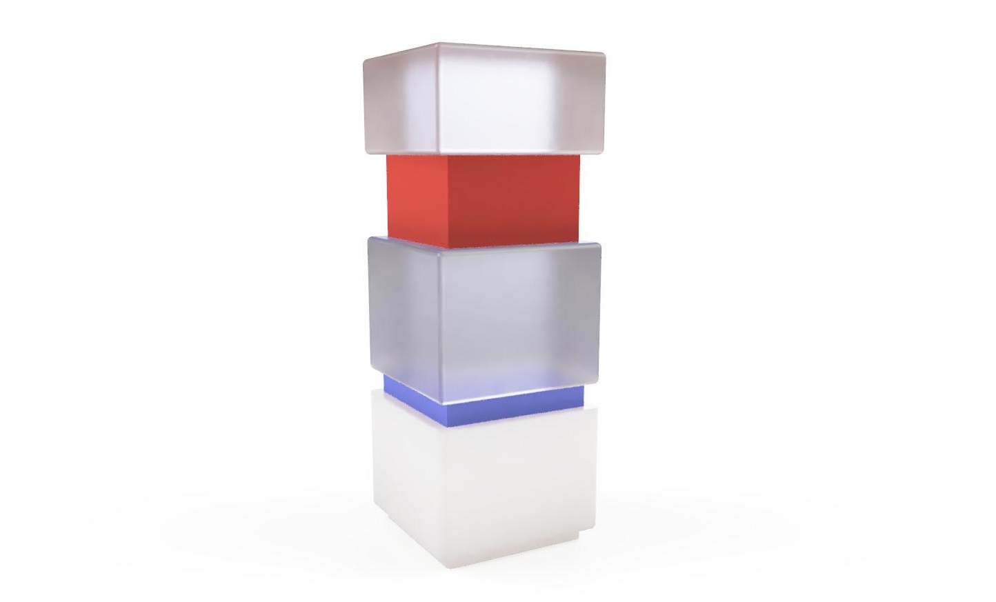
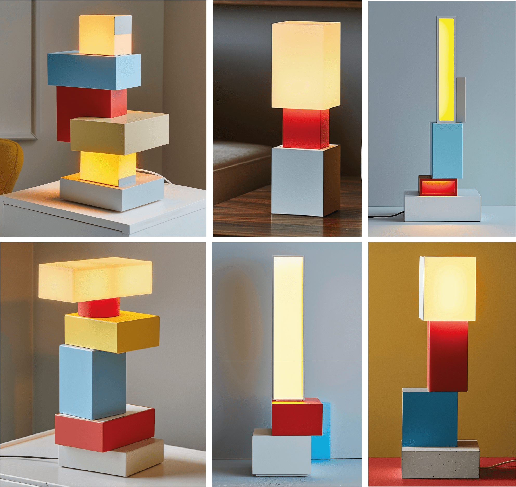
A Modular Touch-Sensitive Lighting Design
For my final project, I aimed to design touch-sensitive modular lighting. On the project, a user can reshape the look of the lighting by reorganizing the modules. Users can attach the connection modules and lighting modules differently at any time.
Secondly, users can change the brightness of the light by using the slider which is placed on the lighting modules. For further improvements to the project number of the modules can be increased and the user can control the LED colors with an app.
Priority Orders of the Features:
Must Have
- Lighting modules with LED.
- Connection modules for electricity transmission.
- Design of lighting and connection modules in such a way that the order can be changed.
- Main module with touch slider to manage the brightness of the lighting modules.
- Communication module for remotely changing the brightness of the lighting.
Time Managment
- Week11- Determine which components are needed.
- Week12- Finalize project idea and user interaction. [Do sketches for form, Work with Midjourney for inspiraiton, Determine product form.]
- Week13- Design PCB.
- Week14- Test the arrangement of the pogo pins on the module lids. Test PCB, LED and pogo pins work well in combination
- Week15- Print the lighting modules on the 3D printer. Cut the connection module on the laser cutter.
- Week16- Complete the main module and connect it with other modules.
Components
| Component Name | Purpose of Having |
|---|---|
| Esp 32 C3 | Microcontroller |
| Pogo Pins | To attach the modules and transfer the electricity. |
| Capacitive Touch Slider | To control the brightness of the LED. |
| Led Strip | To have the light on the lighting modules. |
| Transparent PLA Filament | Having transparent solution on the lighting module. |
| Battery and Charging Module | Main module. |
Inspiration Board
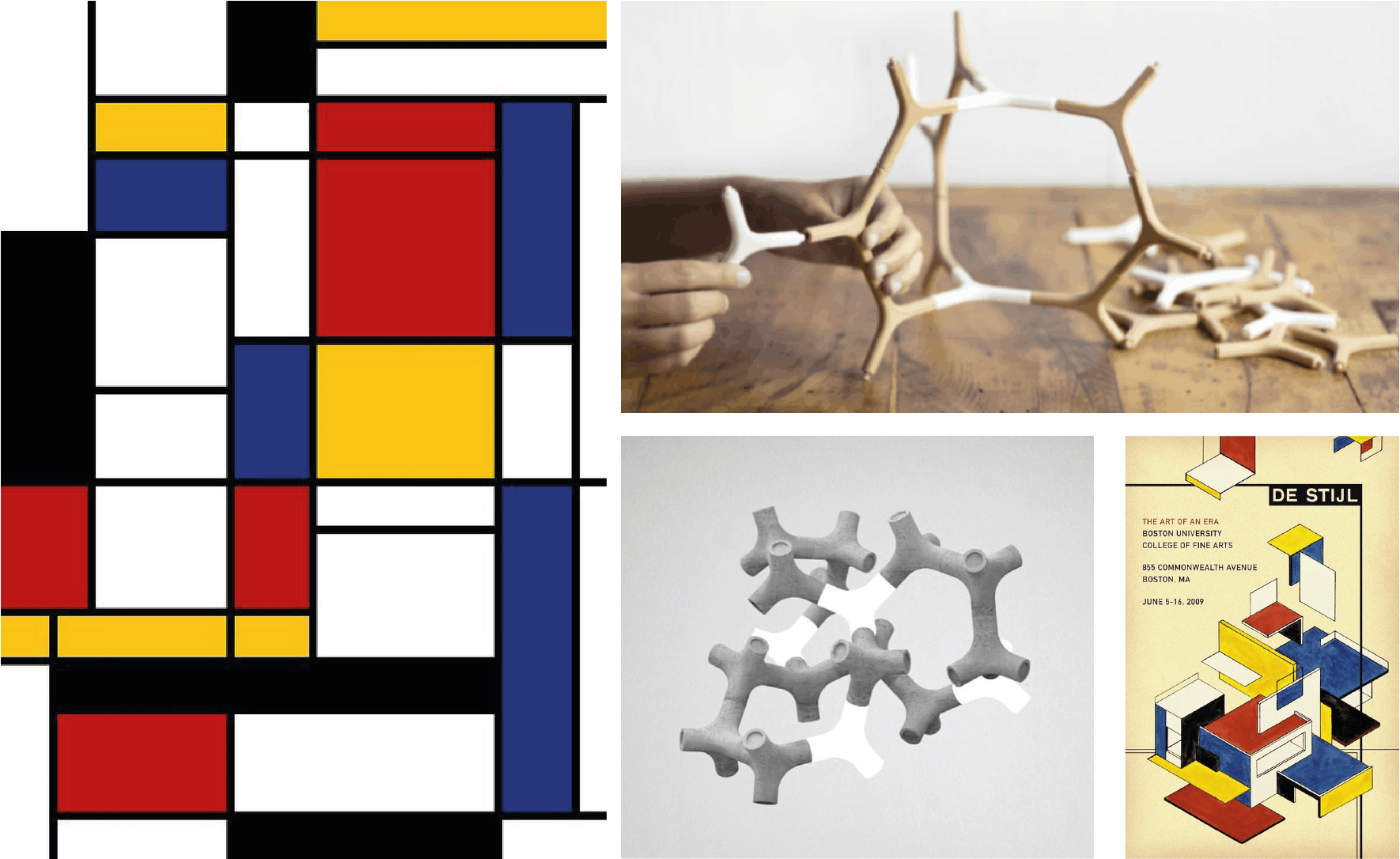
I took my inspiration for the project from the famous Dutch painter Mondrian. His method of simplifying and decomposing objects in his minimal style shed light on my project. Besides, the harmony of blue, white, red and yellow colours he used in his paintings is decisive for my project.
AI-Assisted Form Experiments
I used Midjourney with the help of artificial intelligence during the form search process of my project. When I evaluated the product in terms of ease of use, I concluded that it would be more useful to have a minimal structure rather than having more than one branch of the modules of the product. Following a cubic and vertical form as Modrian did in his drawings will provide ease of use. For this reason, I made a study on this in Midjourney. Here are the results.
Progress on Prototype
1. Testing LED and Power
For the final project, I wanted to test working with LED and power supply. Thus, I used the PCB that I already developed in week 6. In addition to my PCB, I used several different components for testing.
| Component Name | Purpose of Having |
|---|---|
| 3 Female Cable | Attaching to LED |
| 3 Male to Female Cable | Connecting the PCB to the breadboard. |
| Wire Striper | Peeling to cable skin for soldering. |
| Power Supply | Supplying power to LED. |
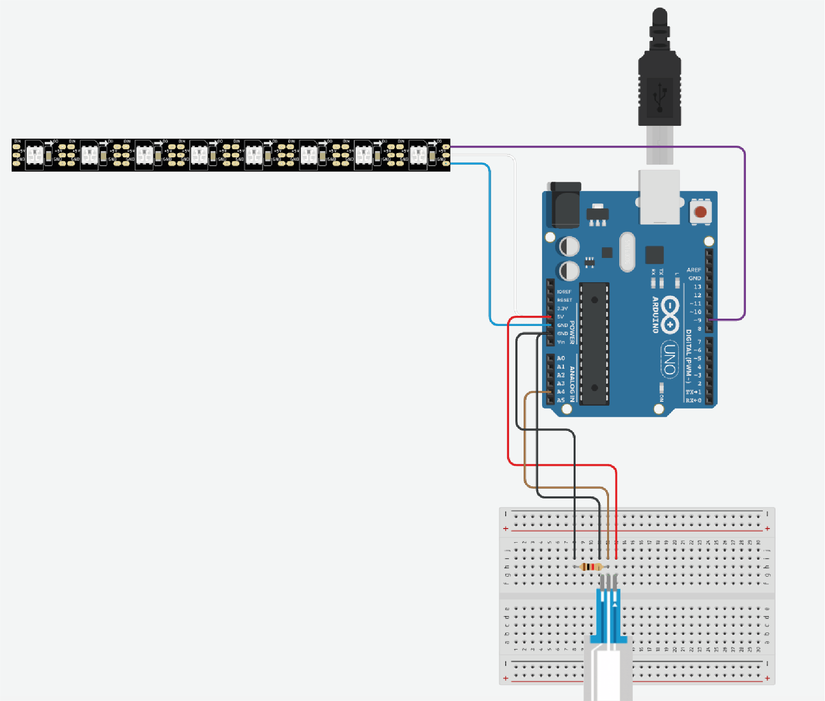
| Force Sensitive Sensor | Using like a button. |
| Breadboard | Connecting sensor, PCB and LED to each other. |
It was my first time working with LED and power suppliers, so my instructor helped me with it. Firstly we cut one side of the 3 female cables and then peeled them with wire stripper. Thus, we could solder them to LED. The black cable is used for ground, the red cable is for 5V, and the orange cable is for transferring information such as color and brightness from PCB to LED.
To connect the LED to the power supplier, we used two power cables. Red cables go to 5V and black goes ground on the power supplier. To connect the PCB to the LED and power supplier, we attached the orange cable to the breadboard. For the orange cable, it wasn't important which pin of PCB they needed to connect. However, for the red and black cables, we choose the ground and 5V pins.
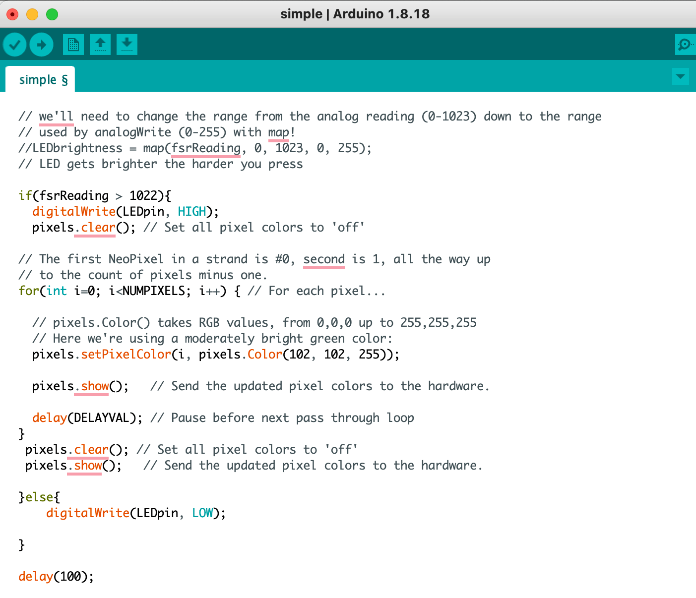
For controlling the LED I combined the button codes from the embedded programming week and LED codes and I sent them to my PCB. To change LED color I used this line of code; pixels.setPixelColor(i, pixels.Color(102, 102, 255)) —-> This line set LED color.
When I press the force sensitive sensor, LED starts to work. However, for my final project I aim to use a slider. For the next step, I will test with capacitive touch slider.
2. Testing Touch Sensor
I aimed to change LED brightness by pressing the sensor’s different places. Thus, I designed my circuit. To design the circuit, I used following components. Also, To control the LED brightness by using the touch sensor, I combined LED codes and touch sensor codes and transferred them to my PCB.
| RGB LED | Output device. |
| Capacitive touch sensor | Input device. |
| Jumper Wires | Connect LED and sensor to the PCB. |
| Breadboard | Connect PCB and sensor. | Type C Cable | To have power from computer. |
#include

const int SOFT_POT_PIN = A4; // Pin connected to softpot wiper

const int GRAPH_LENGTH = 40; // Length of line graph


// Which pin on the Arduino is connected to the NeoPixels?
#define PIN        9 // On Trinket or Gemma, suggest changing this to 1

// How many NeoPixels are attached to the Arduino?
#define NUMPIXELS 8 // Popular NeoPixel ring size


Adafruit_NeoPixel pixels(NUMPIXELS, PIN, NEO_GRB + NEO_KHZ800);

#define DELAYVAL 50 // Time (in milliseconds) to pause between pixels

int colorG =0 ;
int colorR =0 ;
int colorB=0 ;


void setup()
{
Serial.begin(9600);
pinMode(SOFT_POT_PIN, INPUT);
pixels.begin(); // INITIALIZE NeoPixel strip object (REQUIRED)

}

void loop()
{
// Read in the soft pot's ADC value
int softPotADC = analogRead(SOFT_POT_PIN);
Serial.println(softPotADC);
// Map the 0-1023 value to 0-40
int softPotPosition = map(softPotADC, 0, 4095, 0, GRAPH_LENGTH);
colorG = map(softPotADC, 0, 1023, 0, 255);
colorR = map(softPotADC, 0, 1023, 0, 255);
colorB = map(softPotADC, 0, 1023, 0, 255);

//delay(500);
ledStrip();
}

void ledStrip() {
pixels.clear(); // Set all pixel colors to 'off'

// The first NeoPixel in a strand is #0, second is 1, all the way up
// to the count of pixels minus one.
for(int i=0; i< NUMPIXELS; i++) { // For each pixel...

	// pixels.Color() takes RGB values, from 0,0,0 up to 255,255,255
	// Here we're using a moderately bright green color:
	pixels.setPixelColor(i, pixels.Color(colorR, colorG, colorB));

	pixels.show();   // Send the updated pixel colors to the hardware.

	//delay(DELAYVAL); // Pause before next pass through loop
}
}
I connected my circuit to the PCB to have power and test it. And I saw my circuit is working. If I press the left side of the slider there is less LED brightness compared to when I press right side of the slider. However, LED does not maintain last brigtness when I stoped to press it. I need to improve these feature.
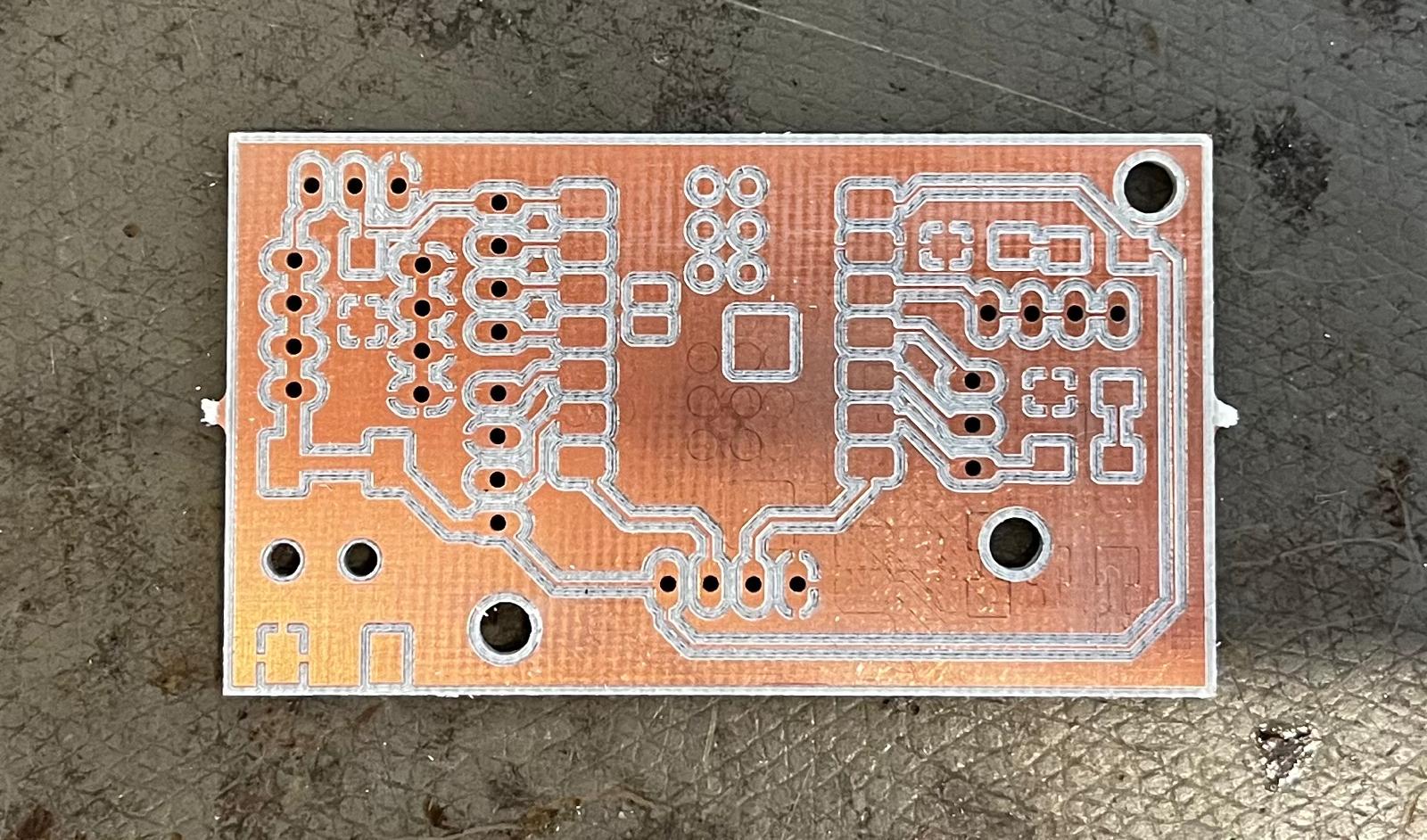
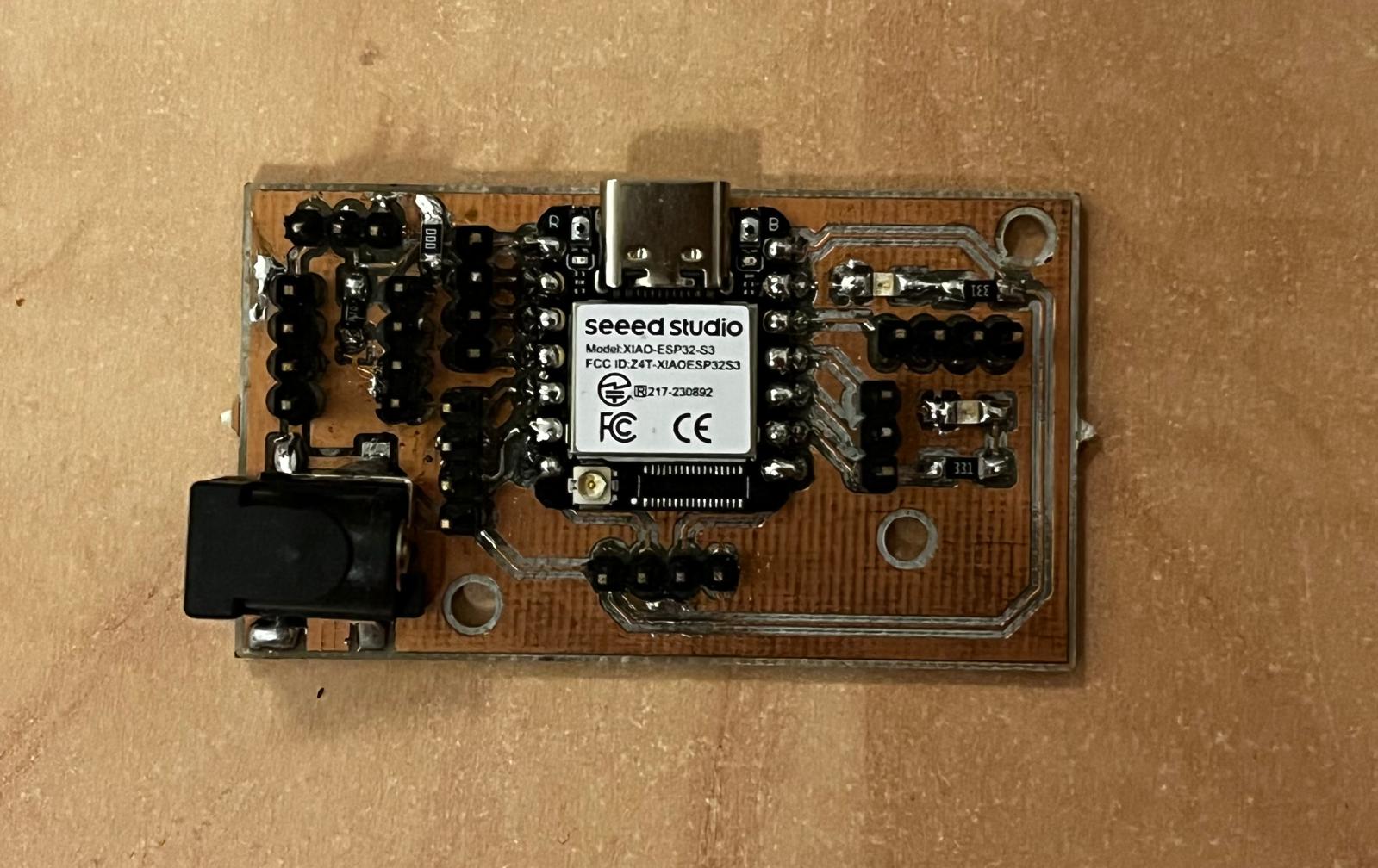
3. PCB Design
The starting point of PCB design was to decide what features I wanted to have in my final project design and design my board accordingly. For this reason, I spent a lot of time on my PCB design to determine my needs in my final design and built my board accordingly. Basically, I needed the following on the PCB;
- Microcontroller- XIAO ESP32S3
- Pins for LED
- Pins for Touch sensor
- Extra pins
- Power connection module
To design my PCB I used the Kicad application as I learned during the electronics manufacturing week. To design my PCB, I used the Kicad program as I learned during the electronics production week. In the Schematic Editor interface of the Kicad software, the user can decide which parts will be on the board and how they will be connected to each other. I used the tools on the right side of the screen to make these arrangements.
I used the triangle sign in the third row from the top right to access the symbol library. I found the parts I needed in the Fab academy library. I connected the parts I placed on the screen by clicking the line sign in the 5th row from the top right.
***Although I used XIAO ESP32S3 in my PCB design, I used the XIAO ESP32C3 symbol in Kicad because the XIAO ESP32S3 library is not currently provided and both microcontrollers have the same outputs.
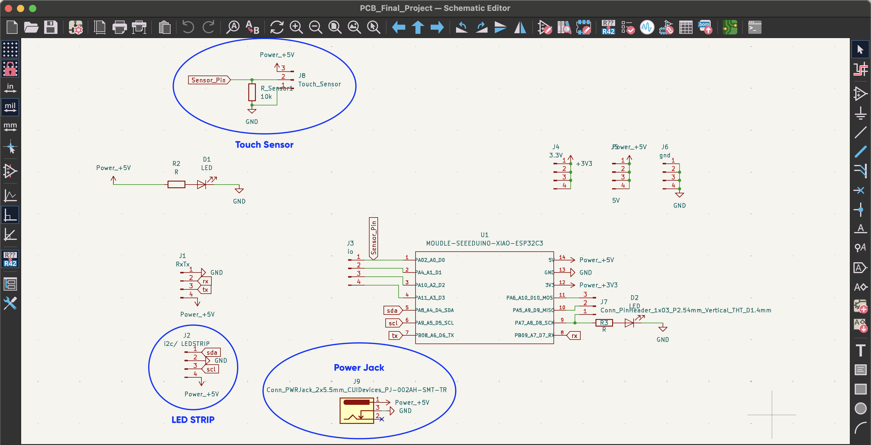
- I connected the touch sensor with 10k resistor, 5V and ground.
- I used a 4-pin header for the ledstrip, I connected ground and 5V to the outputs.
- I connected the power jack with 5V and ground. I did not add anything to one output because when I measured the part I used with an ammeter, I saw that one leg of the part was not connected to anything.
- I also added symbols to the outputs of the microcontroller. These are 3.3V, 5V, ground.
After completing the pin placements and connections, I prepared my design for the PCB editor by following the tools- anotate schematic path. After completing this process, I transferred my drawing to the PCB editor by clicking on the second green box from the right on the top bar.
After transferring my design to the PCB editor, I determined the position and orientation of the parts. For this, following the white arrows made my job much easier. After my placement, I created paths between the parts that need to be connected to each other. By clicking on the cable marker in the right column, third from the top, I got the “Route tracks” tool. After transferring my design to the PCB editor, I determined the position and orientation of the parts. For this, following the white arrows made my job much easier. After my placement, I created paths between the parts that need to be connected to each other. By clicking on the cable marker in the right column, third from the top, I got the “Route tracks” tool.
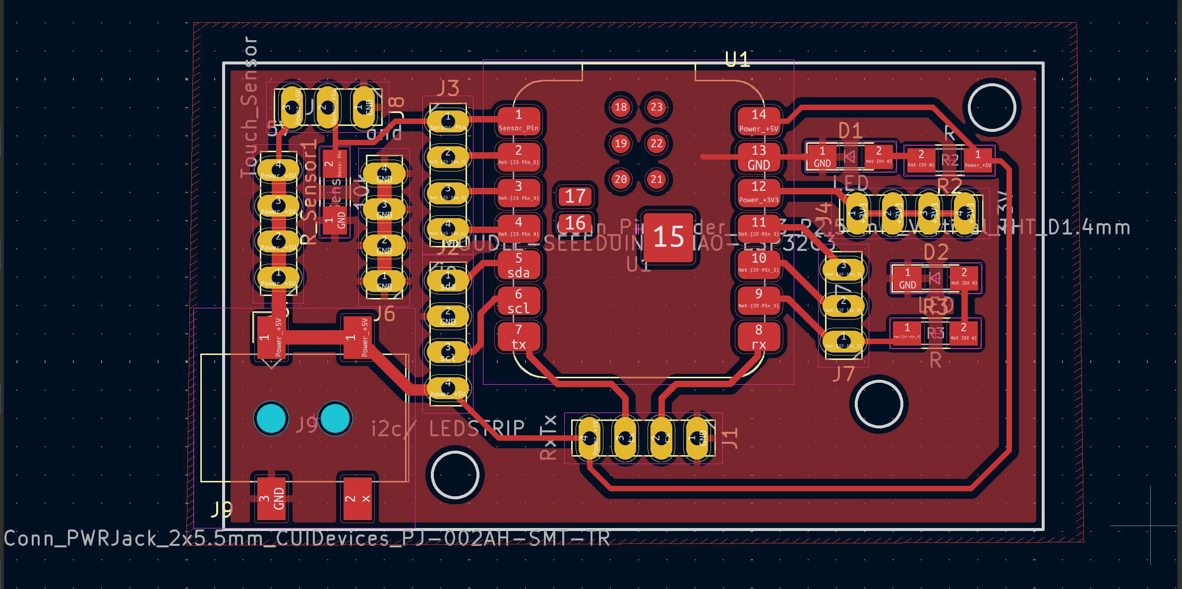
When my design was finished, I prepared my files to create my PCB on the milling machine. For this, I followed this path. File --- Fabrication output --- gerber file. Then, in the window that opens, Plot --- Generate drill file ---- Generate drill file.
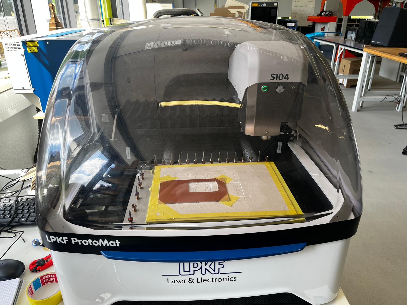
At FabLab Kamplinrfort we use the LPKF laser machine to create our boards. Before transferring my files to the computer, I placed the cutting board on the machine as shown in the image.
4. Pogo Pin Connection Experiments
Pogo pins will help ensure information and electrical exchange between modules in my project. Additionally, since it has magnetic properties, the modules will remain more stable when stacked on top of each other. Pogo pins have 3 outputs. These; 5V, ground and signal outputs. I will revisit these features later in the documentation. Pogo pins will be found in both lighting and connection modules in my project. For this reason, I need to figure out how to connect pogo pins to the product. For this reason, as the first step, I drew the pogo pins in Fusion360.
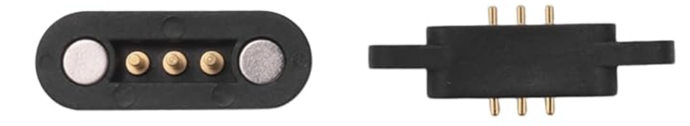
The flow of my test with pogo pins was as follows;
- Pogo pin measurement with caliper.
- Drawing of pogo pins in Fusion360 according to the measurements.
- Drawing of the parts into which the drawn pogo pins can be placed.
- Printing the parts on a 3D printer and evaluating their compatibility with the pogo pins.
I created the sketches of the pogopins in Fusion360 and then extruded them to create the bodies. I did this for both pogopins. When you put two pogo pins on top of each other, they must be aligned. For this reason, I checked to make sure that the top and bottom of the pogo pins in my drawing have the same dimensions. I did this using the measurement tool in the “inspect” section.
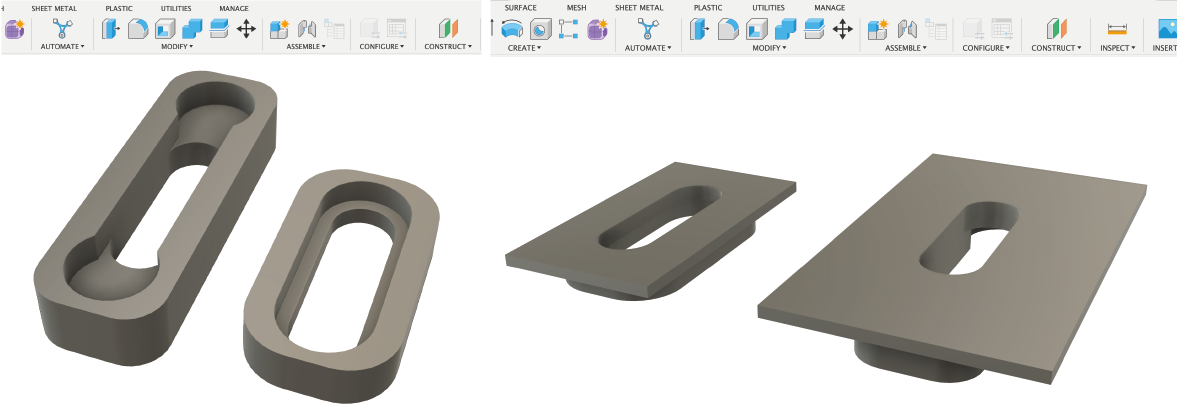
To prepare the places where the pogo pins will be placed, I drew rectangular prisms and created the holes by removing the pogo pins into these prisms. I did this by selecting the “cut” option under the combine tool. Then I drew bottoms for the pieces I created to sit on the floor.
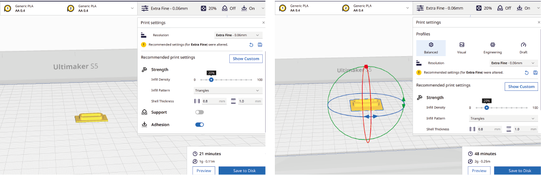
To print the parts I prepared in Ultimaker, I exported them as stl in Fusion360 and imported them into the Cura application. In Ultimaker Cura, I used the recommended settings to print with pla material and turned on the “adhesion” feature so that the parts can adhere to the base of the printer.
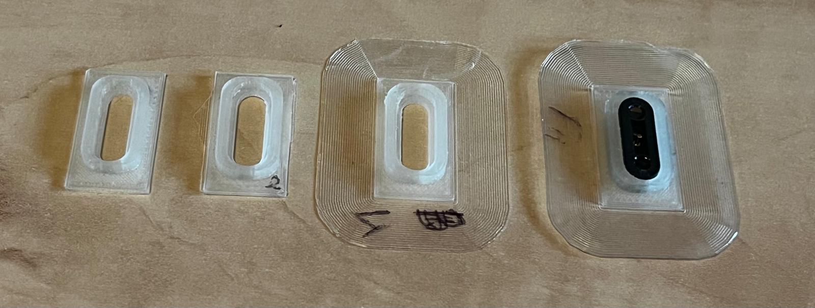
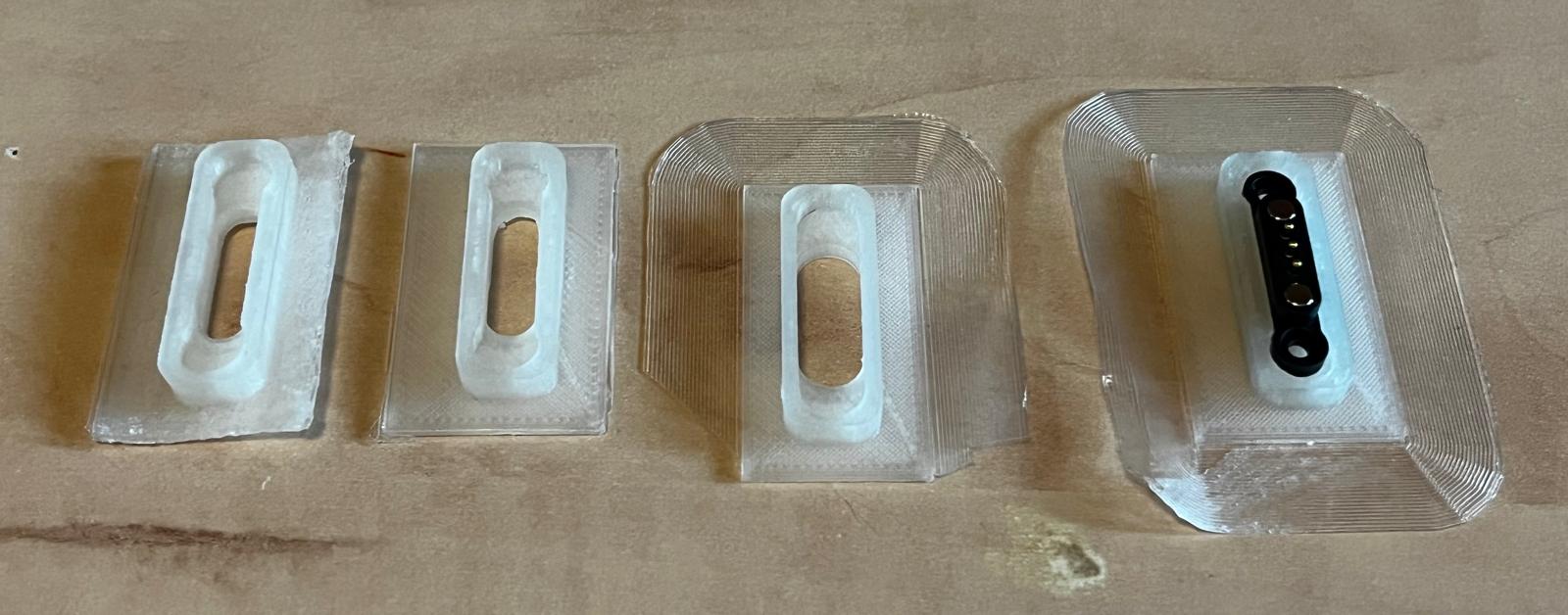
After my 4th attempt, I was able to find the part compatible with the flatpogo pin. During this process, I tried to find the most suitable one by changing the internal dimensions of the parts. I applied the same process to the large pogo pin. I applied the measurements I found on the piece of the flat pogo pin to the piece of the large pogo pin so that the two pieces could fit together.
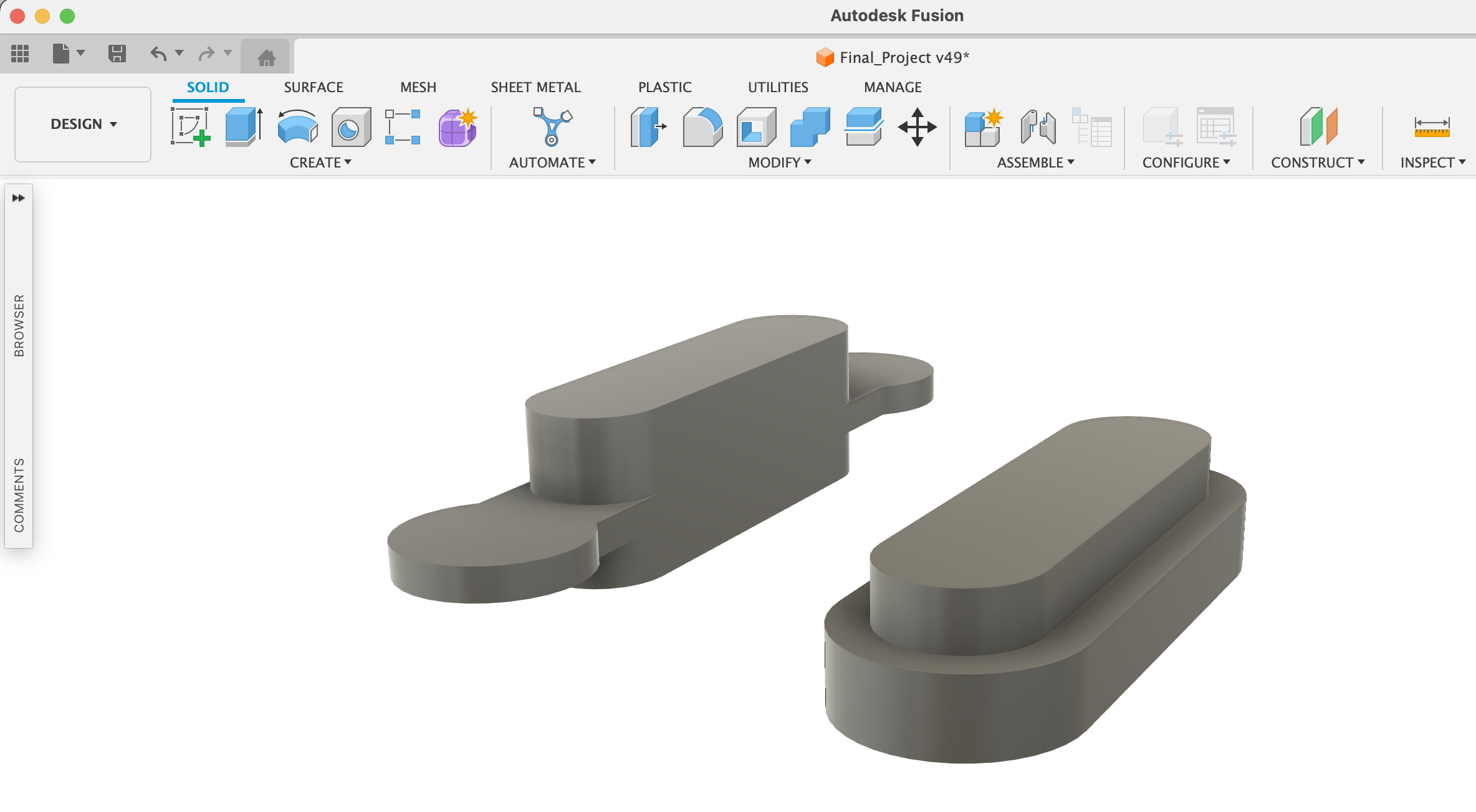
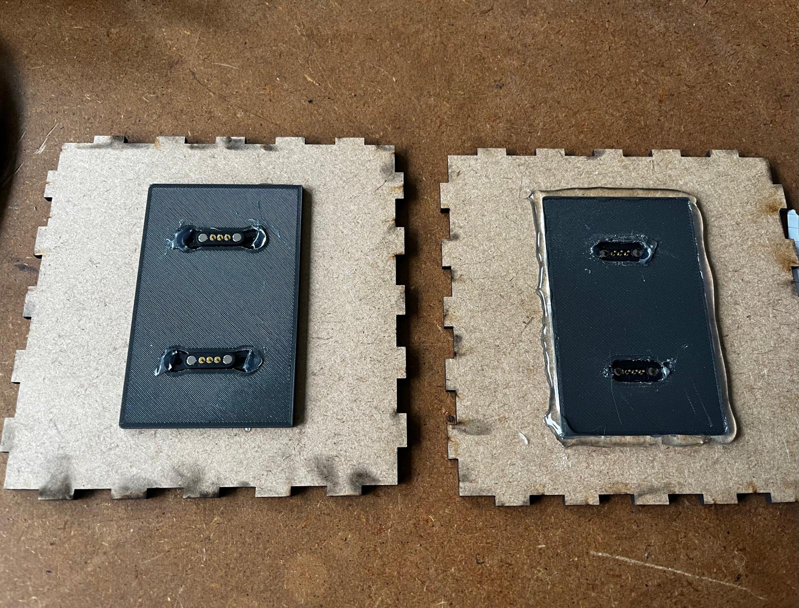
5. Parts to connect the pogo pins to the connection module
After finding the appropriate size of the areas where I could place my pogo pins, I proceeded to the next step. My goal in this step was to design parts that would place the pogo pins in the intermediate modules. For this reason, I used test pieces that I had printed and was satisfied with the dimensions.
- On the covers of the connection modules, the pogo pins will be two and aligned side by side. For this reason, I copied the parts I prepared for the large and small pogo pins during the test phase and aligned the two parts side by side.
- I then created a step so that the prepared parts could fit into the holes in the covers of the connection modules.
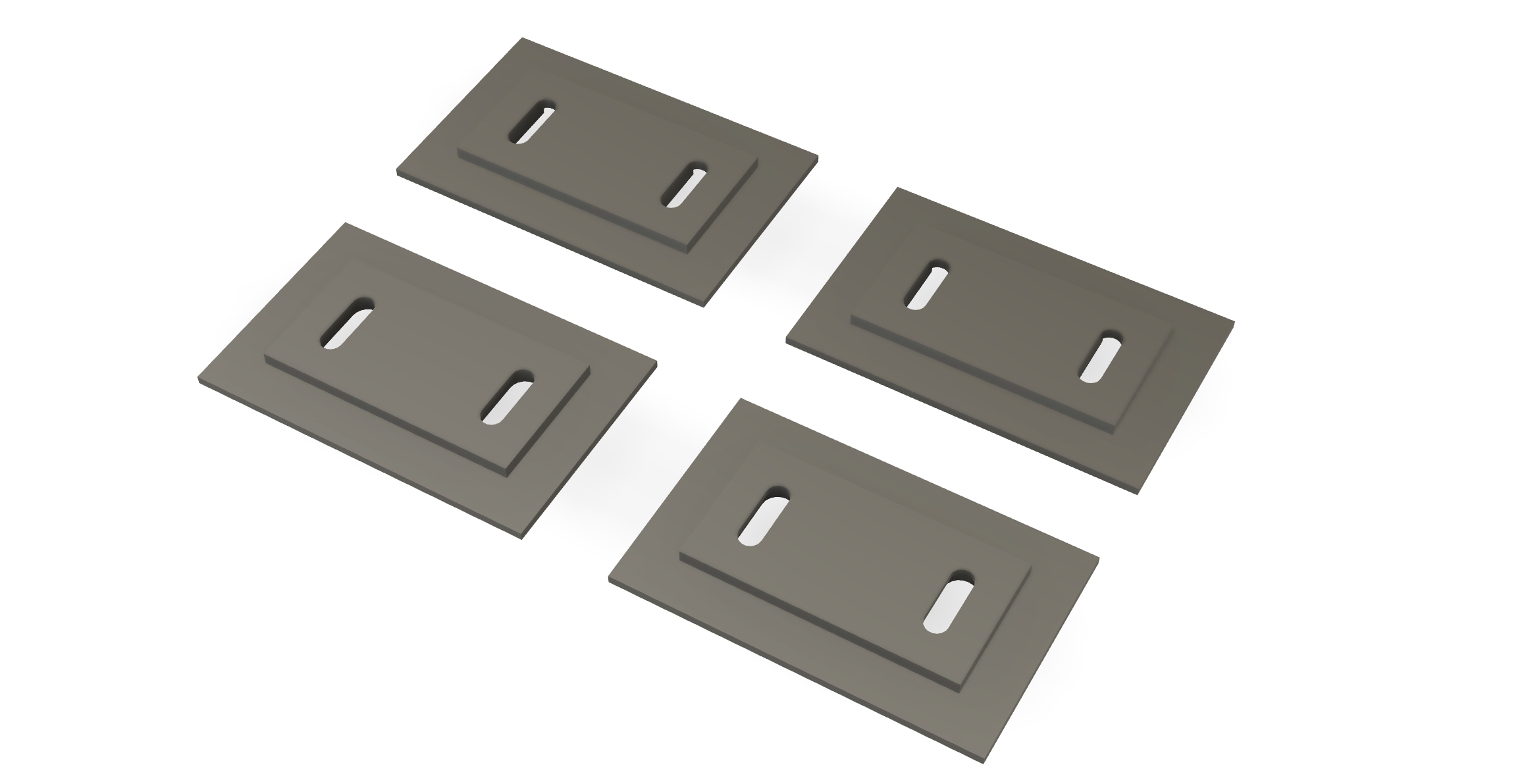
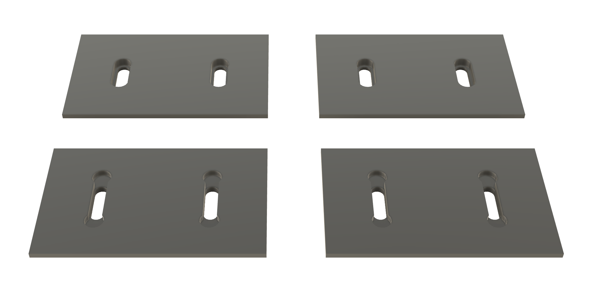
- After completing my design in Fusion, I exported it as stl. Then I opened the 4 parts in Ultimaker Cura to prepare for printing. I used the preset for PLA and added support for the parts with pogo pins.
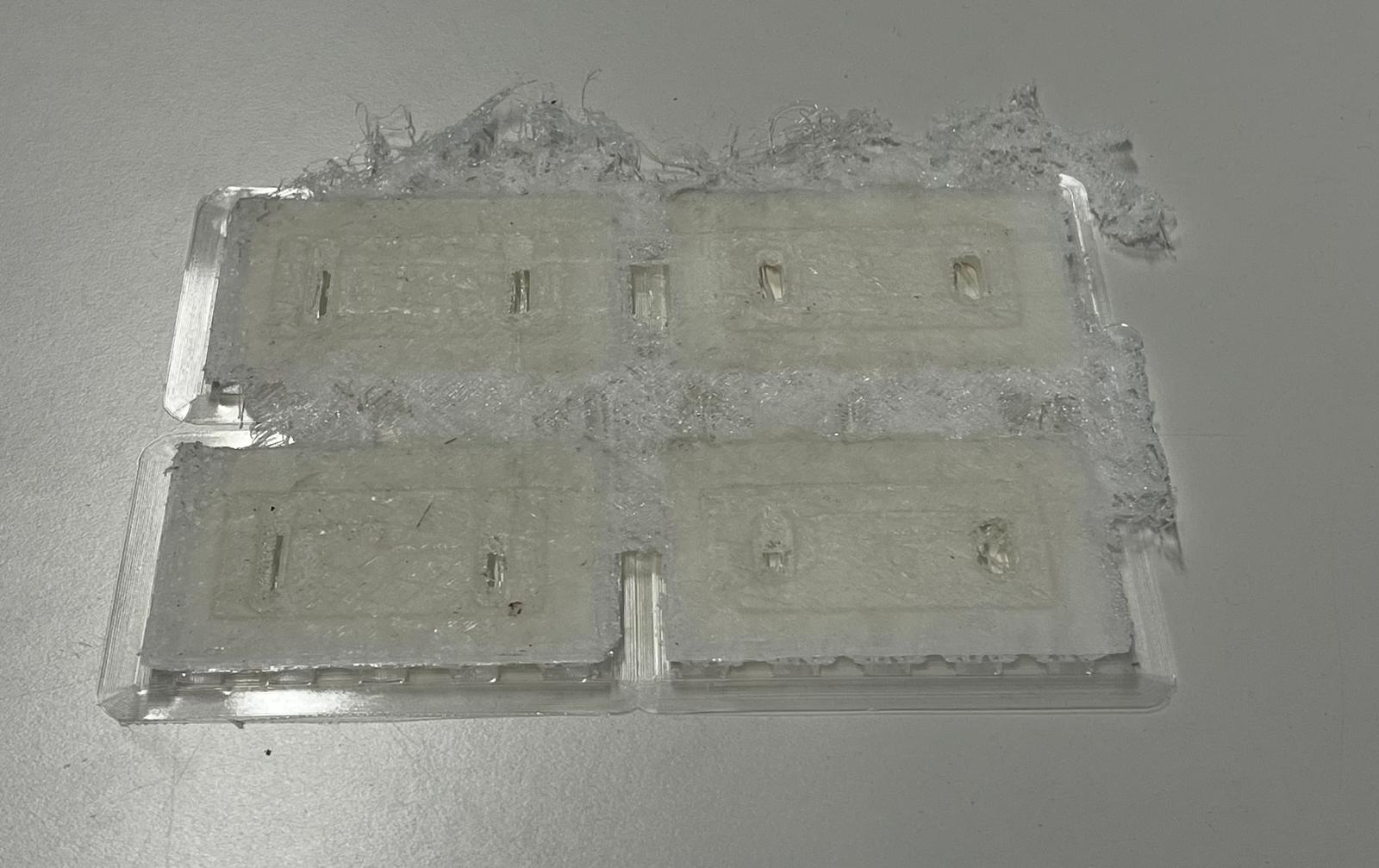
My first attempt was unfortunately unsuccessful, as the printer got stuck in the part during the process, creating a pasta appearance. For this reason, I had to prepare the print again. And on my second attempt, the result was successful.
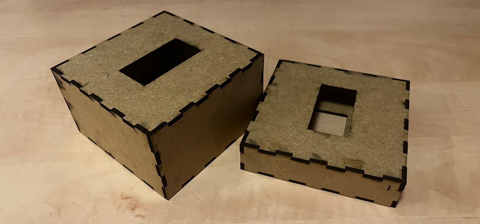
6. Connection Modules
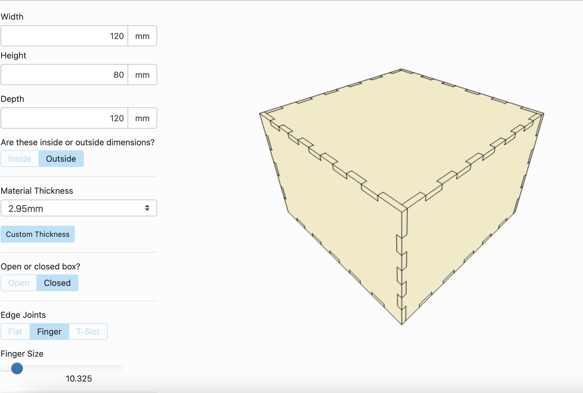
Connection modules connect the lighting modules to each other and provide the passage of electricity and signals. I plan to use these modules in red and blue colors because I was inspired by the paintings of the famous artist Modrian. 2 connection modules at different heights allows the user to create different forms when the user changes the order of the lighting and connection modules. I chose the laser cutting method to produce the connection modules and decided to join the module surfaces using the finger joint method. I used the Maker Case website to complete this process.
In Maker Case, I created a dxf file for the two connection modules. In the interface, I determined the height, width and depth of the prisms. In addition, I determined the material thickness and “finger joint” widths. After making these adjustments, I had the large and small connection parts as dxf.
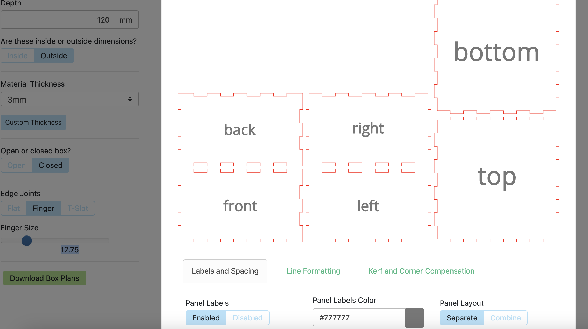
My settings on the interface were as follows for large connection module;
- Width- 120mm
- Height- 80mm
- Depth- 120mm
- Material tickness- 3mm
- Finger Size- 12
My settings on the interface were as follows for small connection module;
- Width- 120mm
- Height- 40mm
- Depth- 120mm
- Material tickness- 3mm
- Finger Size- 12
After downloading the file as dxf to my computer, I imported it into Fusion 360. Here I made some changes to the drawings. I removed the names on the faces of the prism and placed rectangles in the centers. These rectangles are for drilling holes on the faces. I will place pogo pins in these holes in the following process.
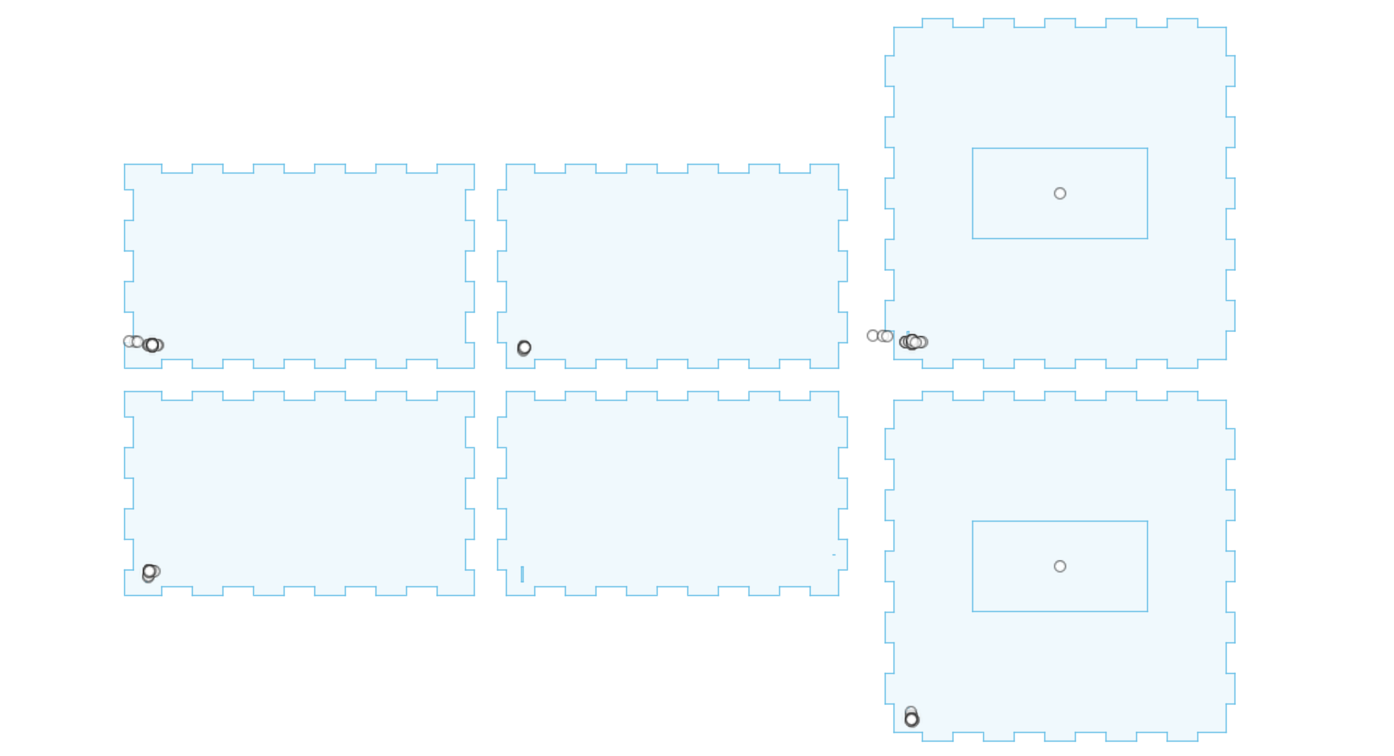
After completing the edits here, I transferred the sketch back to pcy as dxf. I opened the file that I transferred to a USB on the computer connected to the laser cutting machine. On this computer, I opened the file in the Inkscape software. I determined the location of the drawing and opened the print settings tab by clicking on the “print” tab under the File tab. Here I selected the laser machine that was already selected and imported my drawing into the laser machine software.
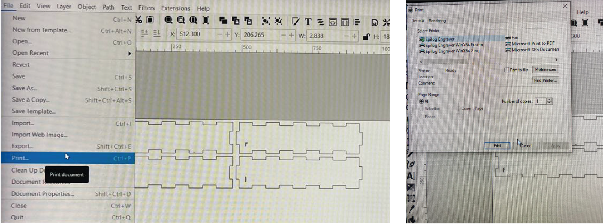
After selecting the laser machine, I set the cutting settings here. When working with MDF during the group assignments, we had already determined the optimal cutting settings for 3mm MDF. I used the same settings here.
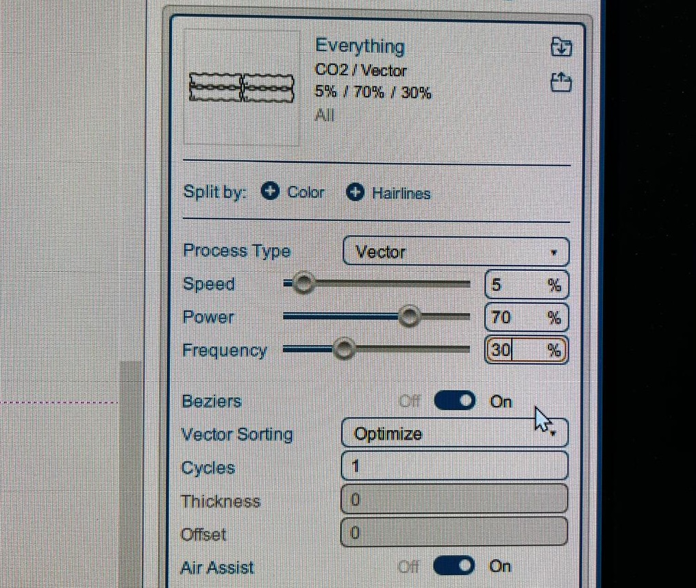
After making these adjustments, my drawing was ready for cutting. After determining the bed height of the laser machine and the location of the jog, I placed the 3mm MDF in the laser machine. After turning on the air pressure as a safety precaution (this is important to prevent smoke and flame), I started cutting. I applied the processes I showed above for both large and small connection modules.
But unfortunately the result was not what I wanted. When I put the pieces together, the prisms were too loose and unstable. For this reason, I decided to make a new cut by changing the material thickness in the MakerCse program.
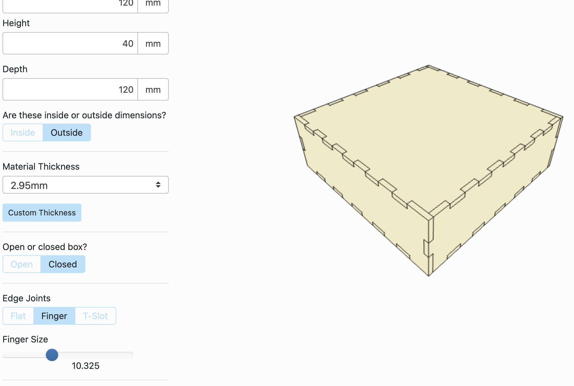
I changed the material thickness to 2.95 and kept the other settings the same. Then I saved it as dxf again and repeated the same process. After the cutting was completed, I put the pieces together and I was very happy with the result, all the pieces held together easily.
7.Connecting Pogo Pins and Connection Modules
I used hot glue to join the printed parts to the covers, but again my first attempt failed. In my first attempt, I put the glue between the two parts while combining the printed part with the cover. But this method would prevent the pogo pins from communicating with each other. Because the adhesive created a layer and the pins I printed were not aligned with the surface of the covers. For this reason, I removed the glued parts and applied the glue to the edges of the parts I printed.
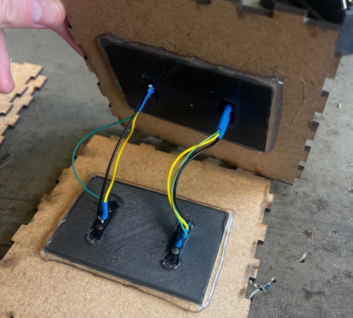
8.Pogo Pins Connections
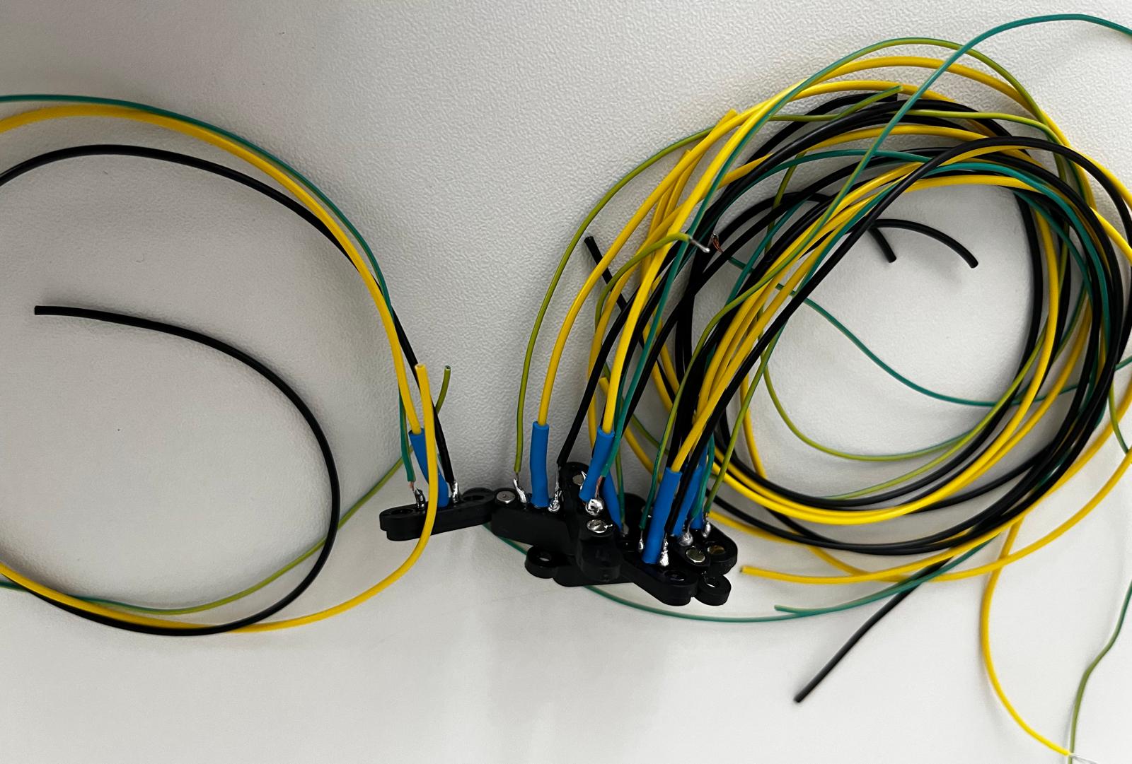
After hot gluing the pogo pins to the fittings, I spoke to my supervisor to plan the system integration. It was very important to adjust the connections of the pogo pins because the LEDs should work and not cause a short circuit when we rotate the modules 180 degrees and place them. For this reason, we did the work on the paper below. We defined the pogo pins respectively as Signal - 5V - Ground. On the opposite pogo pin, we followed the sequence Ground - 5V - Signal. In this logic, even if the module is rotated 180 degrees, it will not cause a short circuit. I also colour coded according to the pins;
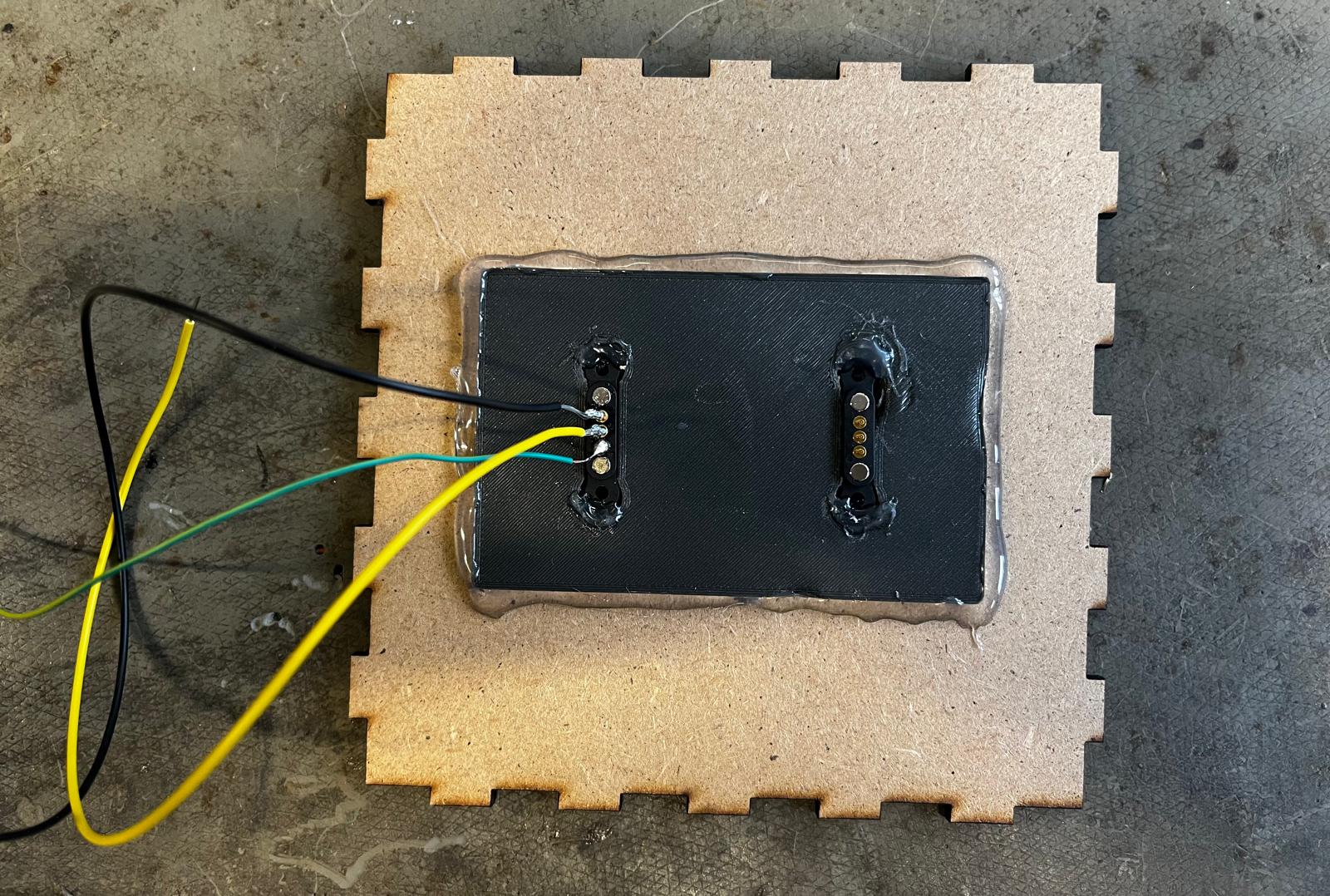
- Green cable - Signal
- Yellow cable - 5V
- Black cable - Ground
I prepared the cables to connect the pogopins. Firstly, I cut the cables of equal length, then I separated the outer casing with a cable stripper. I followed the following steps when soldering the wires to the pogo pin;
- I created a base by leaving some iron on the ends of the cables I cut.
- I did the same with the pins. I tried to leave a small amount of iron on the pins, which was quite difficult. Because the solder had difficulty holding the pin and slipped. Later, when I asked my supervisor, he said that there was a coating on the pins and if we sanded it, the metal would hold the pins more easily.
- Then, when I brought the cable and pin closer together and heated the metal, the pin and cable came together.
- Before connecting the wires to the pogo pins on the other cover, I added a protection and heated it with a hot air gun to prevent the wires from shorting each other.
Vinyl cutting for Connection Module
After completing the system integration for the connection modules and assembling the laser cut parts, I prepared the modules for vinyl cutting. I decided to cover the large and small connection modules with red and blue vinyl. The reason for this was that I was inspired by the artist Piet Modrian in my design. To cover the modules, I followed this process;
- I calculated the perimeter of the modules and created a couple of different rectangles in the illustrator according to this measurement.
- I exported the drawing I prepared as png.
- I imported the file into "Silhouette Studio".
- I made the settings for cutting in the programme. I selected the paper size and cutting shape and sent the drawing to the cutting.
- I put the vinyl on the cutting board and placed it in the vinyl cutter.

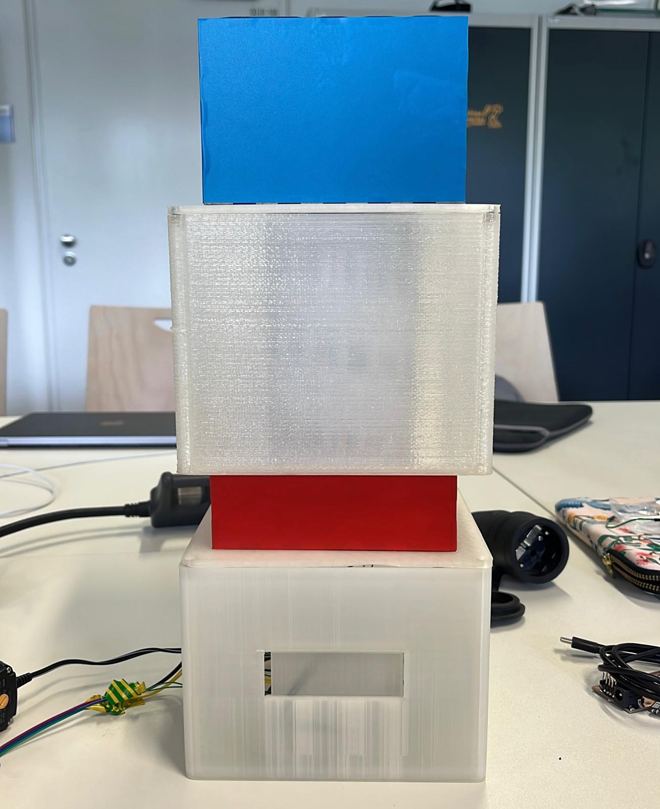
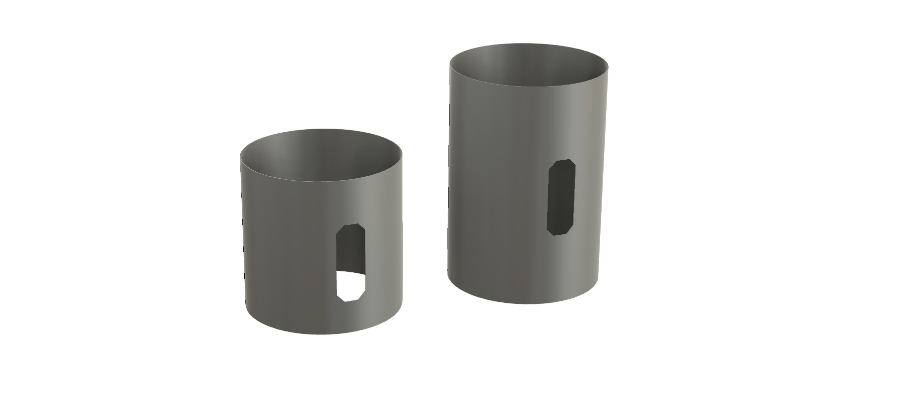
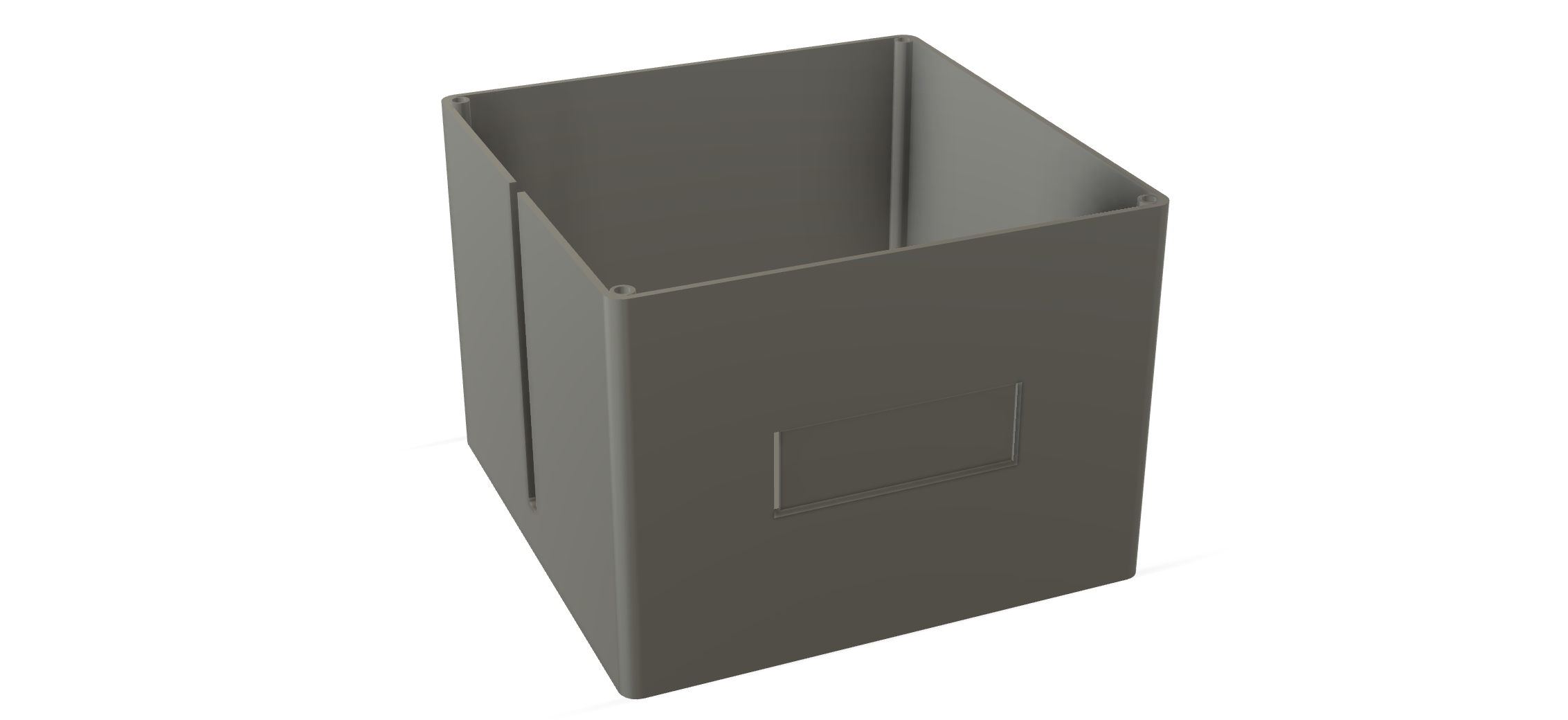
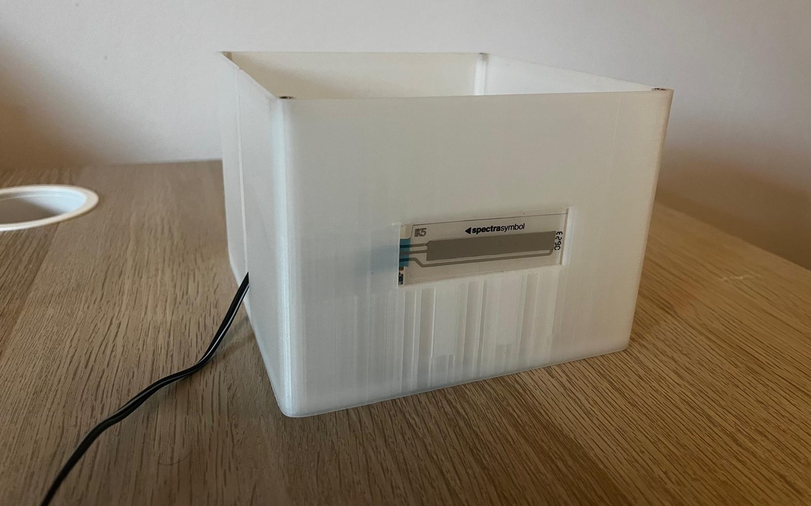
9. Lighting Modules
I designed the lighting modules in Fusion360 and produced them using 4 different 3D Printers. I had to solve some problems in order to print the design on a 3D printer. My supervisor helped me in this process. Also, I used a small and a large lighting module in my design, both of which had different design processes.
First Design - Big Lighting Module
In the initial design of the lighting, there were sections connected to the lower and upper surface and where the lighting could sit on the cover. But when I came to the printing stage in the 3d printer, the lower and upper surface and the areas where the covers would be connected had to have support in order to be printed. But ultimaker cura warned me that support cannot be applied in designs with 90 degree overhang.
For these reasons I had to change my design to another version without overhang. My supervisor helped me at this stage.
Second Design - Big Lighting Module
For these reasons I had to change my design to another version without overhang. My supervisor helped me at this stage.
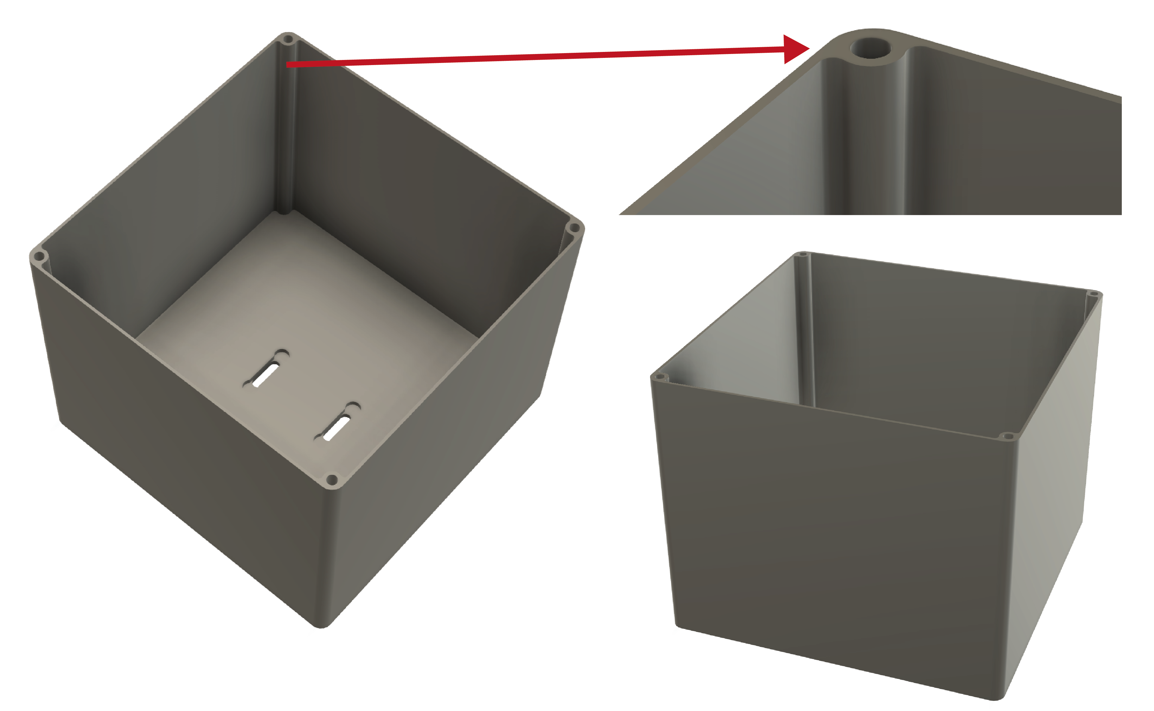
In the second design, we focused on solving the overhang problem. For this reason, we made changes in the areas where the covers will be connected to the body. Firstly, I drew the body of the lighting in Fusion360. Then I created a new sketch and made a drawing for the holes where the covers will be connected. After finishing the sketch, I created a new body by extruding. I also created a surface on the base of the lighting and placed the holes I created for the pogo pins on the base of the lighting.
Printing Big Lighting Module
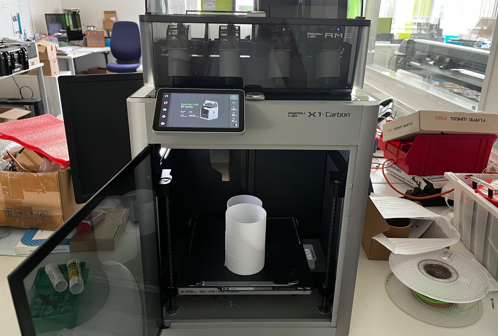
I used the Bigrep printer in the lab to print the lighting. And I used Verbatim 2.85mm transparent material.
I created the gcode of my design I prepared in Bigrep's slicer application and saved it to a USB drive. Then I inserted the usb stick into Bigrep and selected the file I wanted to upload. After uploading the file, I had to wait for the machine surface to heat up. It needs to reach about 250 degrees. But since the machine is very large, this takes some time.
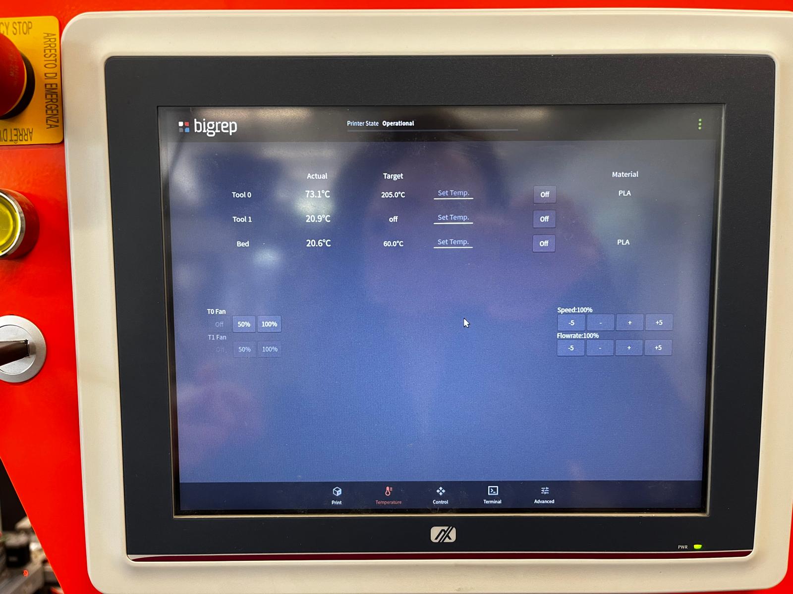
As a result of the printing, there were distortions where the pogo pins would be connected. I think this is because the printer is too big and cannot print small details.
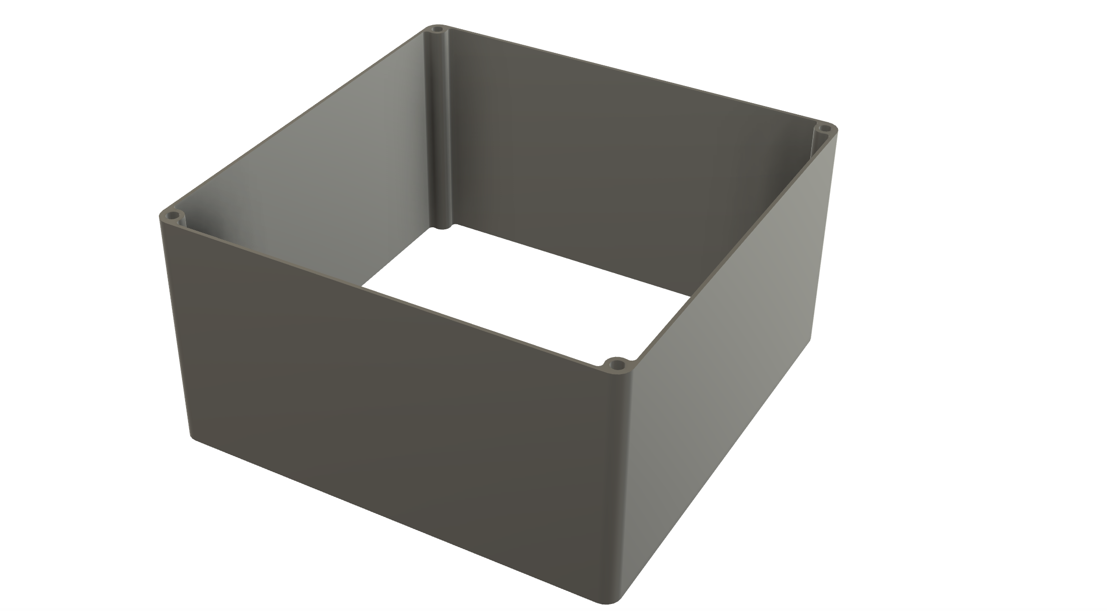
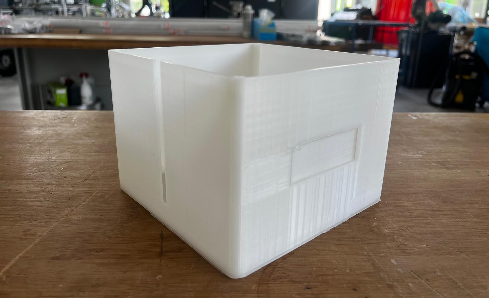
Small Lighting Module
Due to the printing problem in the large illumination, I decided to design the small illumination module to leave both sides open. In the design, I shortened the length of the large illumination and deleted the base surface using the extrude tool.
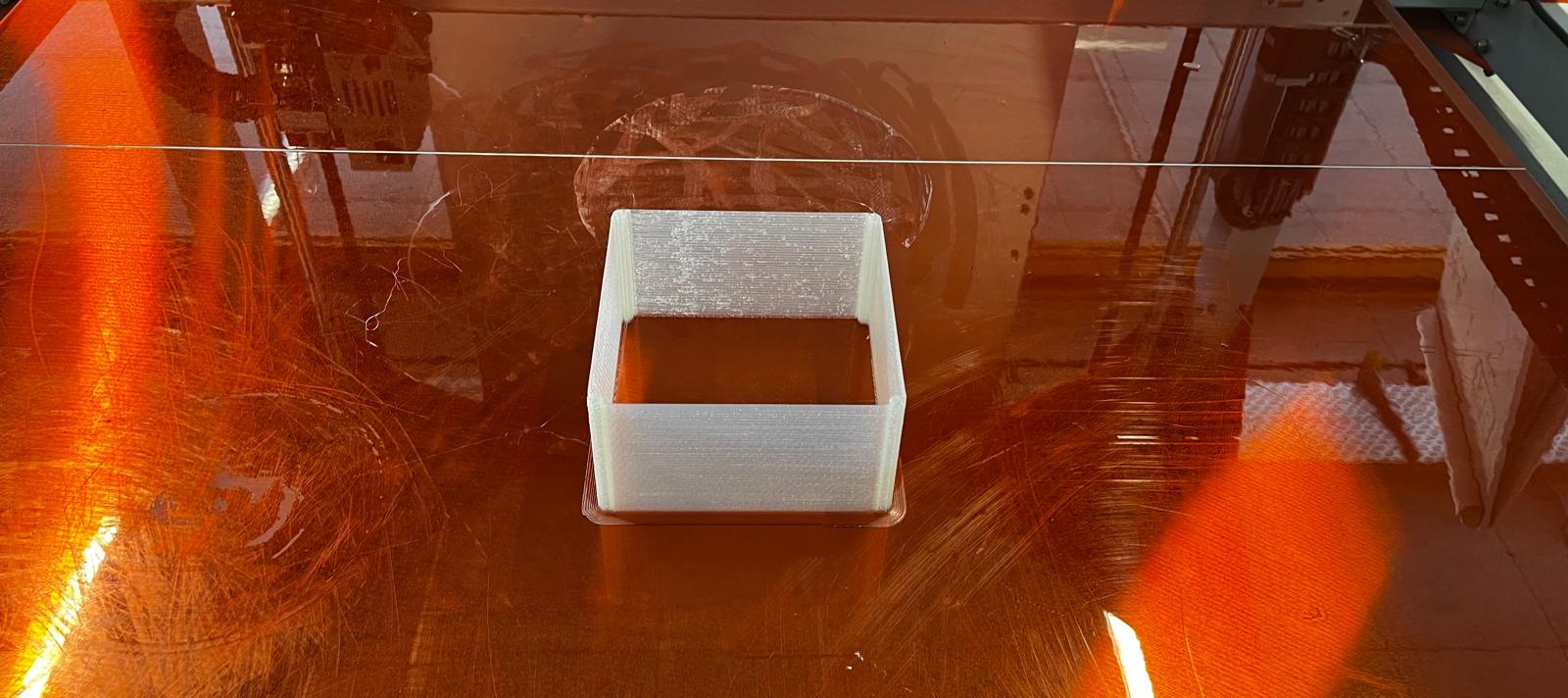
Printing Small Lighting Module
I opened my design again in Bigrep's slicer software and created Gcode. I followed the same process again and transferred my design to Biprep.
10. Lighting lids
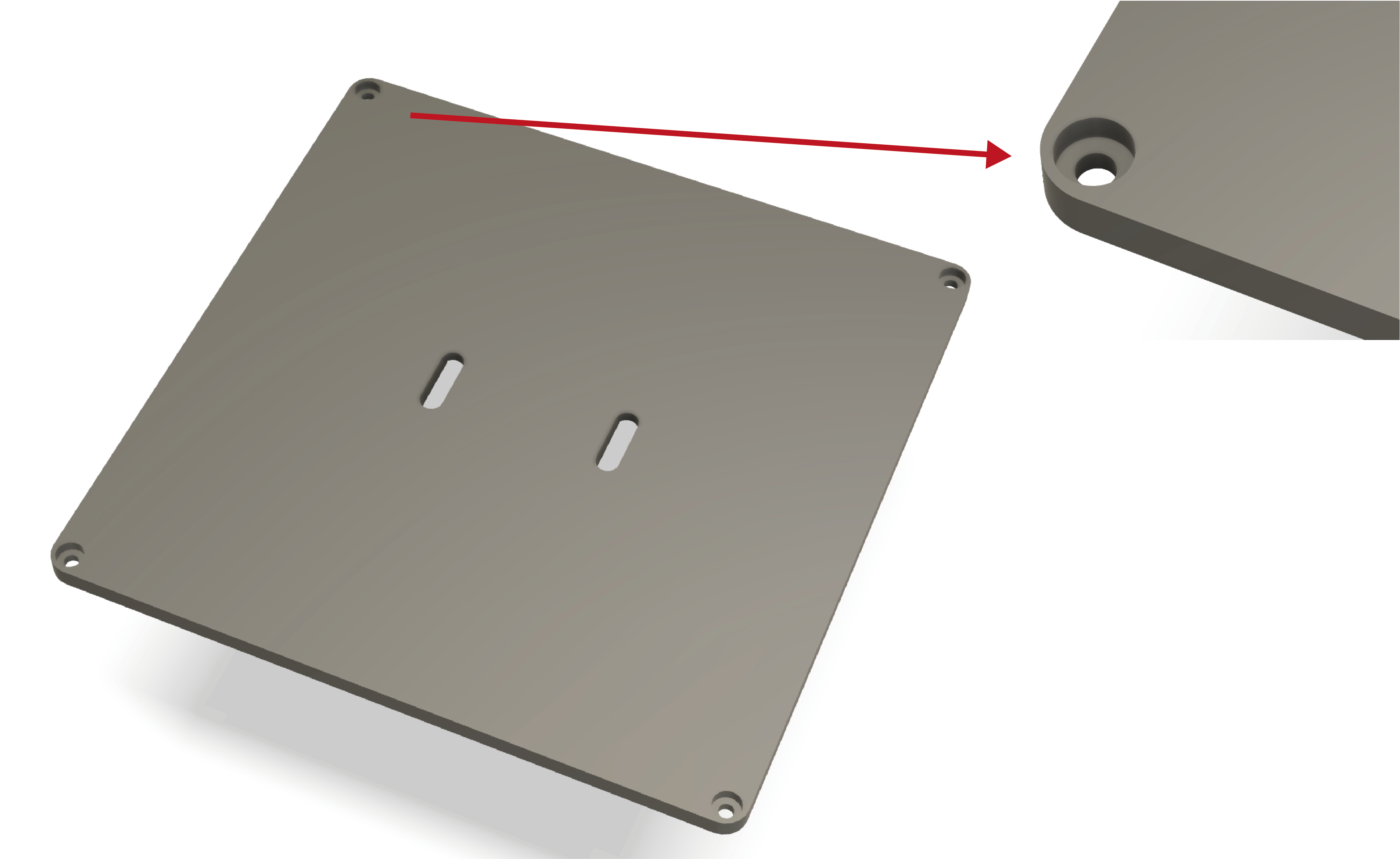
After designing and printing my 2 lighting modules, it was time for the lighting lids where the pogo pins will be placed. When designing, I started by creating a sketch of the lid. While creating the sketch, I took the dimensions of the body and the places where the holes were. After completing it, I extruded it. The holes in the body and the lid are the size that a 3mm screw can enter.
While testing the pogo pins, I placed the bodies I created on the lid and by removing the two bodies from each other, I created holes in the lid where the pogo pins will be placed.
Printing Lids
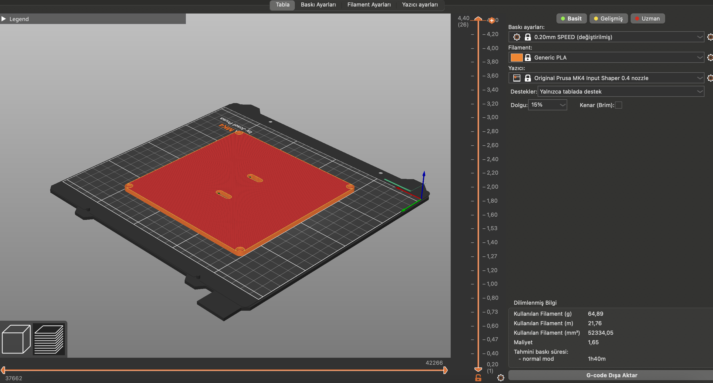
I printed the covers in Prusa. I used the ready-made generic PLA setting for the print settings. I printed the lids in Prusa. I used the ready-made generic PLA setting for printing settings. After slicing the design, I transferred it to the Prusa usb stick as Gcode and placed the stick in Prusa. After selecting the design in Prusa's interface, Prusa started printing. The reason I chose Prusa was to get a high quality output and to speed up the process.
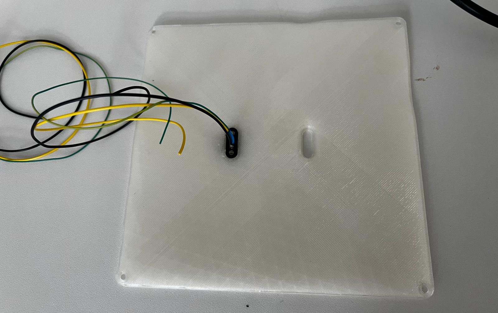
I started to place pogo pins on the lids I printed. While the lids were being printed, I prepared the pogo pins that I would place on the lids. While preparing the pogo pins for the lighting modules, I applied the same process as the pogo pins I prepared for the connection modules. I paid attention to colour coding and covered the soldered parts with plastic to prevent the wires from touching each other.
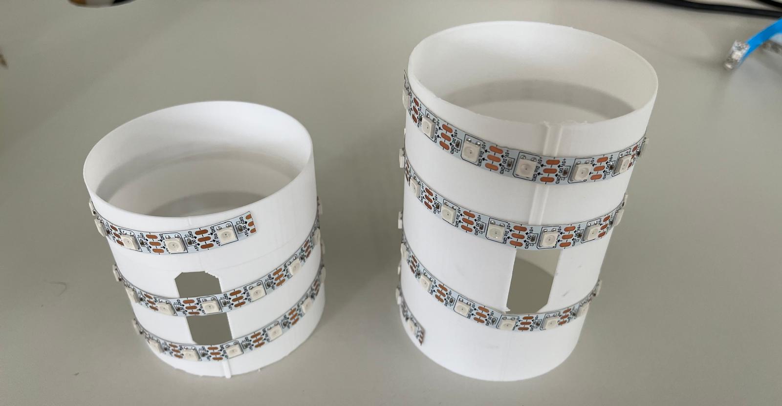
11. LED Placement on the Lighting Modules
Although I did not include it in my design at the beginning of the process, I later realised that I needed a part where I would place my LEDs. For this reason, I designed cylinders that I would place inside the lighting modules. I made the heights of the cylinders equivalent to the height of the lighting modules and made gaps in the centre for the cables to pass through. To speed up the process, I printed the cylinders on a bamboo printer.
12. System Integration for Lighting Modules
Firstly, I soldered the pogo pins on one cover to the LED, then I glued the cylinder to the base of the lighting with hot glue and placed the pogo pins on the other cover to the other end of the LED.
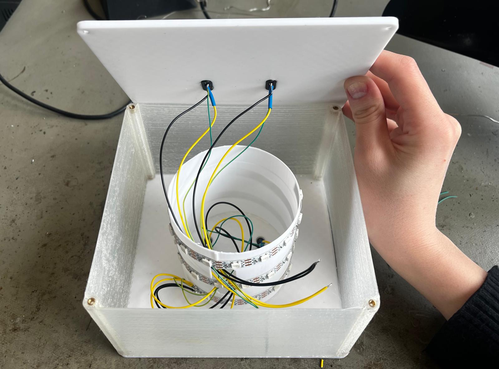
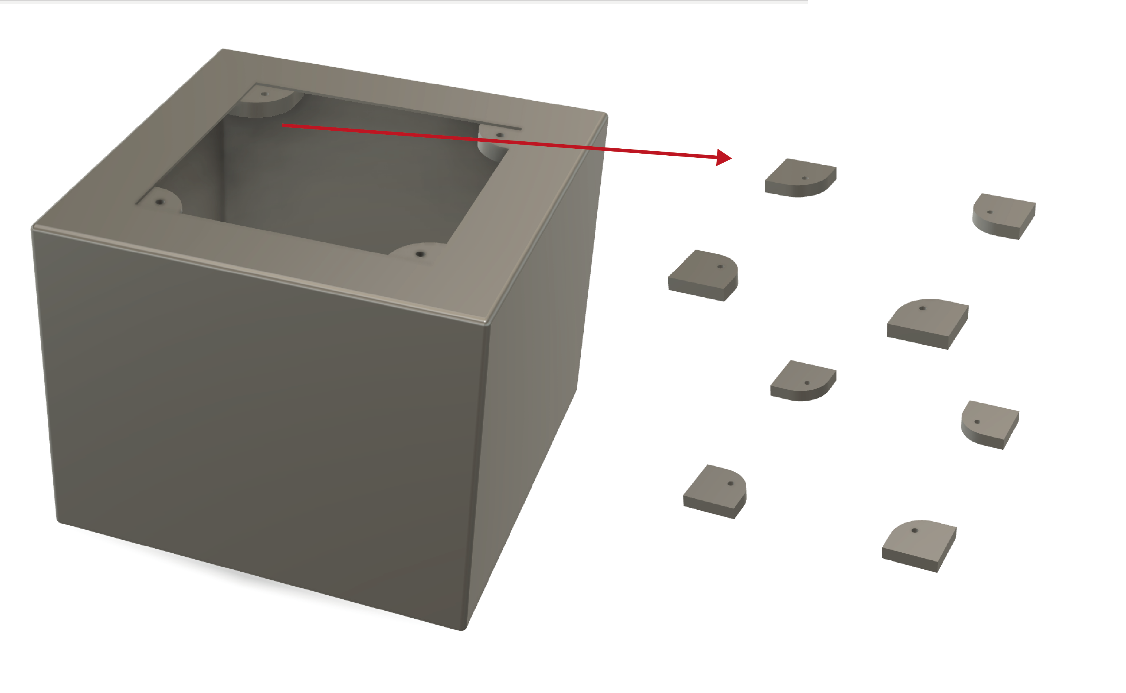
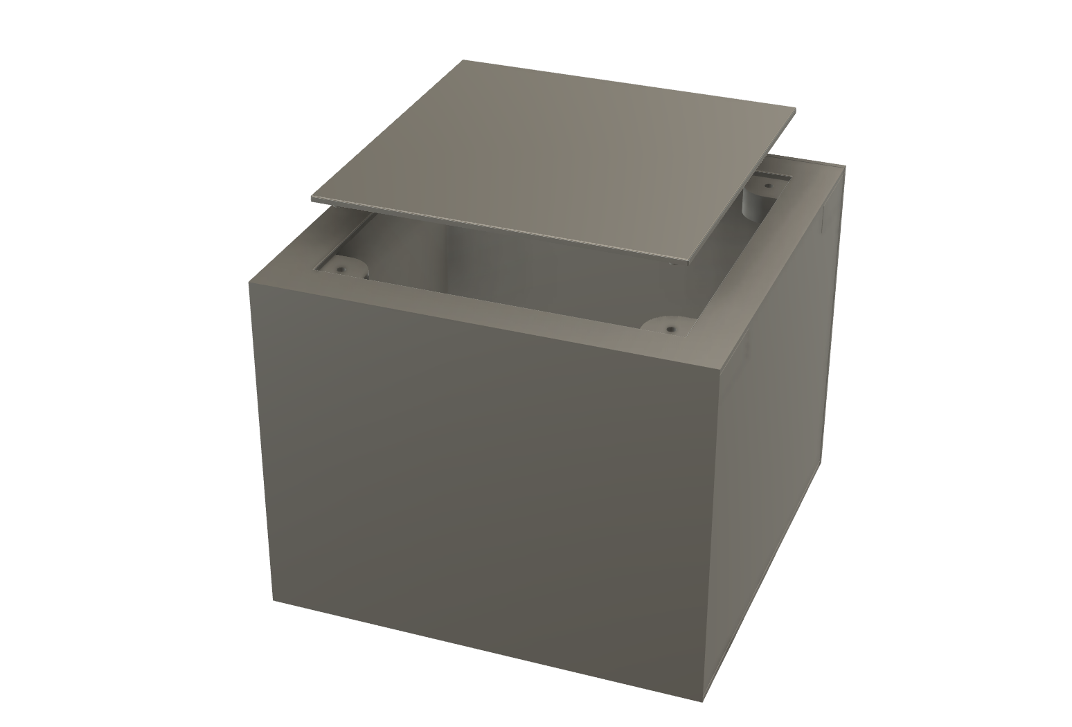
12. Main Module
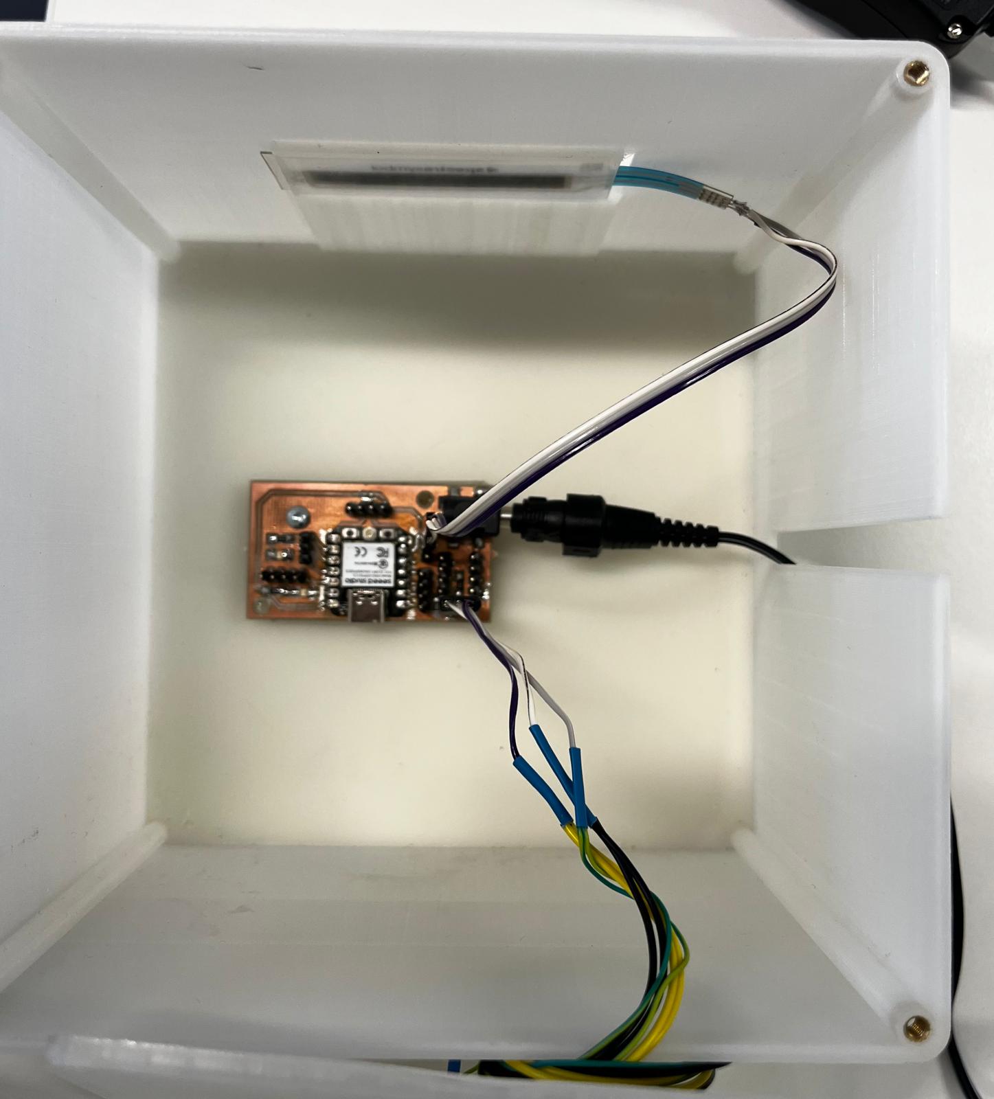
The main module is one of the most important parts of my projects. The main module includes pcb, sensor, pogo pin on the main module cover. For this reason, I had to design a place where the sensor would be positioned in the main module. I also needed a space where the pcb would be connected to the power supply.
During the design process, I made sure that there was no overhang in the design, because in this case I have to add a support and it reduces the design quality. Similar to other processes, I sliced the design in Ultimekar Cura and created a gcode.
After completing the printing of the main module, I placed screw steps in the gaps in the main module in order to be able to connect it with the lid. After heating the steps with a soldering machine, I slowly placed them in the gaps. The heated part melted the gap of the module a little and allowed it to settle.
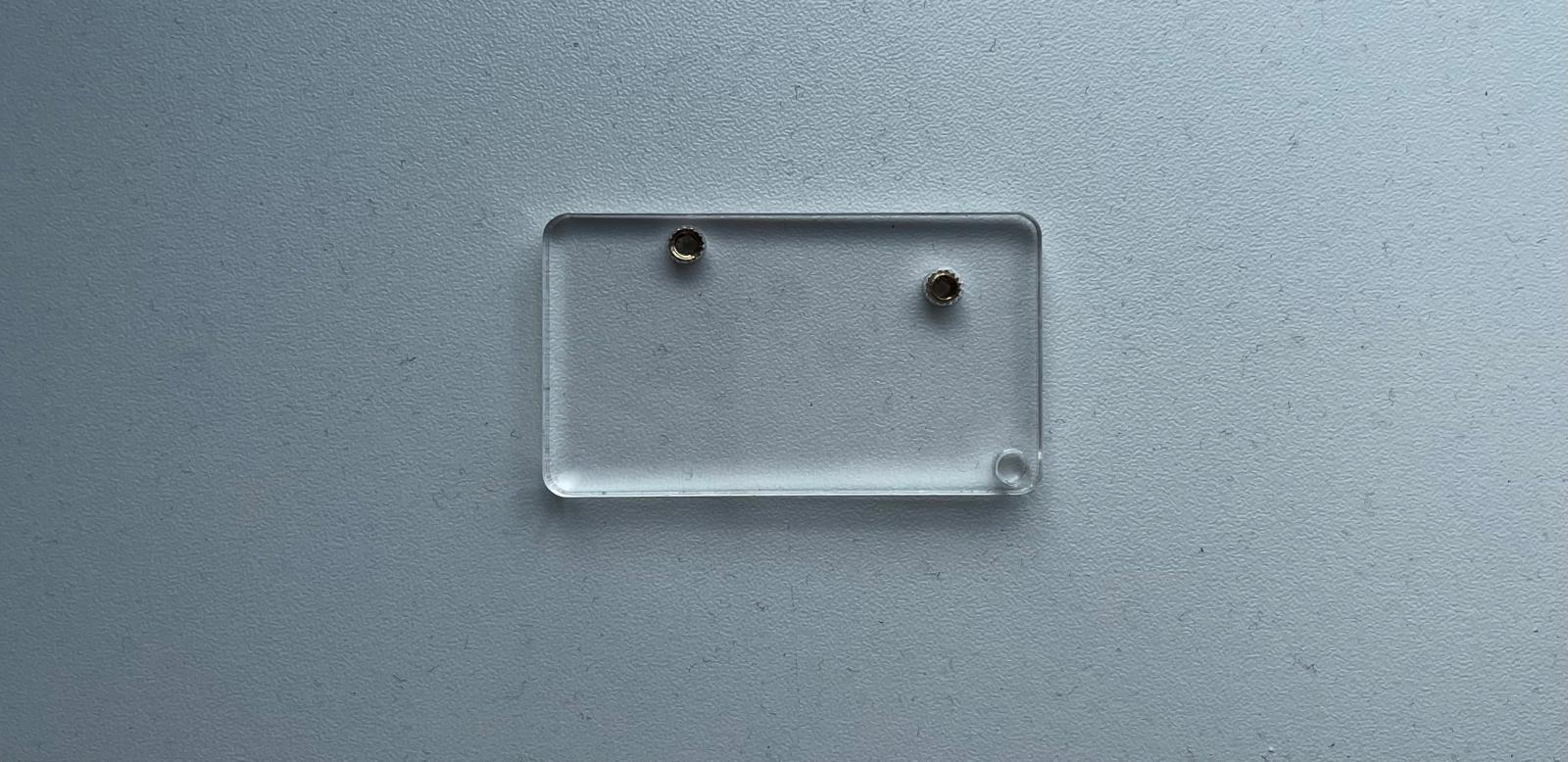
I designed a holder to place the PCB on the main module. I had the outline of the PCB through the file I created in KiCad and used this file to cut a plexi glass. I obtained my holder by using the file I exported as dxf on the laser cutting machine. I applied double-sided tape to the back of the plexi I cut and screwed the PCB to the plexi, then placed the PCB to the main module with the tape.
I have prepared all the parts that I will place inside the main module. These are in order as follows: PCB with holder, touch sensor, power cable. Now it's time to place these parts into the main module.
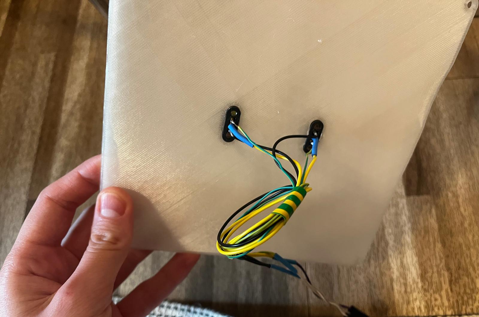
While printing the covers for the lighting modules, I also printed one for the main module. I realised the connection of the main modules with pogo pins as follows. The pogo pin placement of the main module is very important because they determine how the other modules will be connected. I positioned the pogo pins on the main module so that the green signal cable is at the bottom left. This means that the modules that will be placed on the main module must match the pogo pins located on the main module and even if I rotate the modules 180 degrees, the cable order in which the pogo pins are connected must be the same.
13. programming
After the design, printing and cutting of all the modules was completed, I focused on programming the sensor to work. I had worked on this part during the input week, but there were points that needed to be improved. The sensor did not continue the last data it detected and I had used a long sensor in the input week, then I preferred to use a short sensor for ease of placement in the design. For this reason, there were codes to be changed in programming.
#include

const int SOFT_POT_PIN = A0; // Pin connected to softpot wiper

const int GRAPH_LENGTH = 8; // Length of line graph


// Which pin on the Arduino is connected to the NeoPixels?
#define PIN        D5 // On Trinket or Gemma, suggest changing this to 1

// How many NeoPixels are attached to the Arduino?
#define NUMPIXELS 180 // Popular NeoPixel ring size


Adafruit_NeoPixel pixels(NUMPIXELS, PIN, NEO_GRB + NEO_KHZ800);

#define DELAYVAL 50 // Time (in milliseconds) to pause between pixels

int brightness =0 ;

int oldBrigthness = 0;

int colorG =0 ;
int colorR =0 ;
int colorB=0 ;

int tempValue = 0;


void setup()
{
Serial.begin(9600);
pinMode(SOFT_POT_PIN, INPUT);
pixels.begin(); // INITIALIZE NeoPixel strip object (REQUIRED)

}

void loop()
{
// Read in the soft pot's ADC value
int softPotADC = analogRead(SOFT_POT_PIN);
//Serial.println(softPotADC);
// Map the 0-1023 value to 0-40
int softPotPosition = map(softPotADC, 0, 4095, 0, GRAPH_LENGTH);
tempValue = map(softPotPosition, 0, GRAPH_LENGTH, 0, 255);
Serial.println(tempValue);

if (tempValue != 0){
brightness=tempValue;
if (tempValue < 33) brightness=0;

if(brightness!=oldBrigthness)ledStrip();

}


/*colorG = map(softPotADC, 0, 1023, 0, 255);
colorR = map(softPotADC, 0, 1023, 0, 255);
colorB = map(softPotADC, 0, 1023, 0, 255);*/

//delay(500);
}

void ledStrip() {
pixels.clear(); // Set all pixel colors to 'off'

// The first NeoPixel in a strand is #0, second is 1, all the way up
// to the count of pixels minus one.
for(int i=0; i< NUMPIXELS; i++) { // For each pixel...

// pixels.Color() takes RGB values, from 0,0,0 up to 255,255,255
// Here we're using a moderately bright green color:
pixels.setPixelColor(i, pixels.Color(brightness, brightness, brightness));

pixels.show();   // Send the updated pixel colors to the hardware.

}
oldBrigthness=brightness;
}