My Final Project
Dynamic Synth - A mixer that produces unique sound based on motion in real time

My final project is a sound mixer that can produce unique sound in real time base on the movement of the device. It's an attempt for me to expreriment with synthesizing sound and doing audio processing on a microcontroller.
It's a small device that you hold in your hand. It constantly generates the sound with a waveform stored in the device. When the button on the front is pressed, it starts to record the movement and rotation data of itself, and it modifies the waveform based on the input, thus altering the sound that it outputs. The frequency, which determines the pitch of the sound is not affected by the input, but is supposed to be streamed in using the USB port or through the network(currently not implemented, so the device just plays several notes hard coded inside the program now) so that it transforms the music that's streamed in based on it's movement.
Final Presentation Video
Project Development
For my final project, I want to make a synthesizer that produces sounds that are based on the input of different sensors, which can achieve unique sounds for different physical properties of the environment.
Ideation
Digital music and sound generation is a topic that I have always wanted to explore, previously in college I had a project that used capacitive sensor to sense the electromagnetic field and use the values to produce sound, but it was just changing the frequency of the buzzer based on the signal and didn't generate sound as a synth would do, I want to look further on this direction. There are tons of projects out there for making synths but I don't want to just redo the existing projects. And for my only experimentation, I want to approach it from a more fundamental way and see if I can make something different.
So I did some research on the basics of the synthesizers and learned that, because the pitch of a sound is determined by the frequency of the sound wave, the key to creating different sounds is to make the different wave patterns in the period of the wave. Any pattern of the wave can be created by adding up fundamental waves like sine waves, so the synthesizers work by combining and manipulating sound signals coming from an oscillator with different filters and effects.
A lot of synths in the past were built with analog circuits to do the processing and transform of the signal, nowadays these works can be done by software, I think there's no point for me to build a synth functioning the traditional way. I wanted to try making a synth that maps the harmonic characteristic directly from some sensors' input instead of doing the signal transformation. The idea is to see if I can generate unique sounds from different sensors' input based on the different characteristics of the input signal.
Sketch
Below are sketches explaining my concept and final project device.
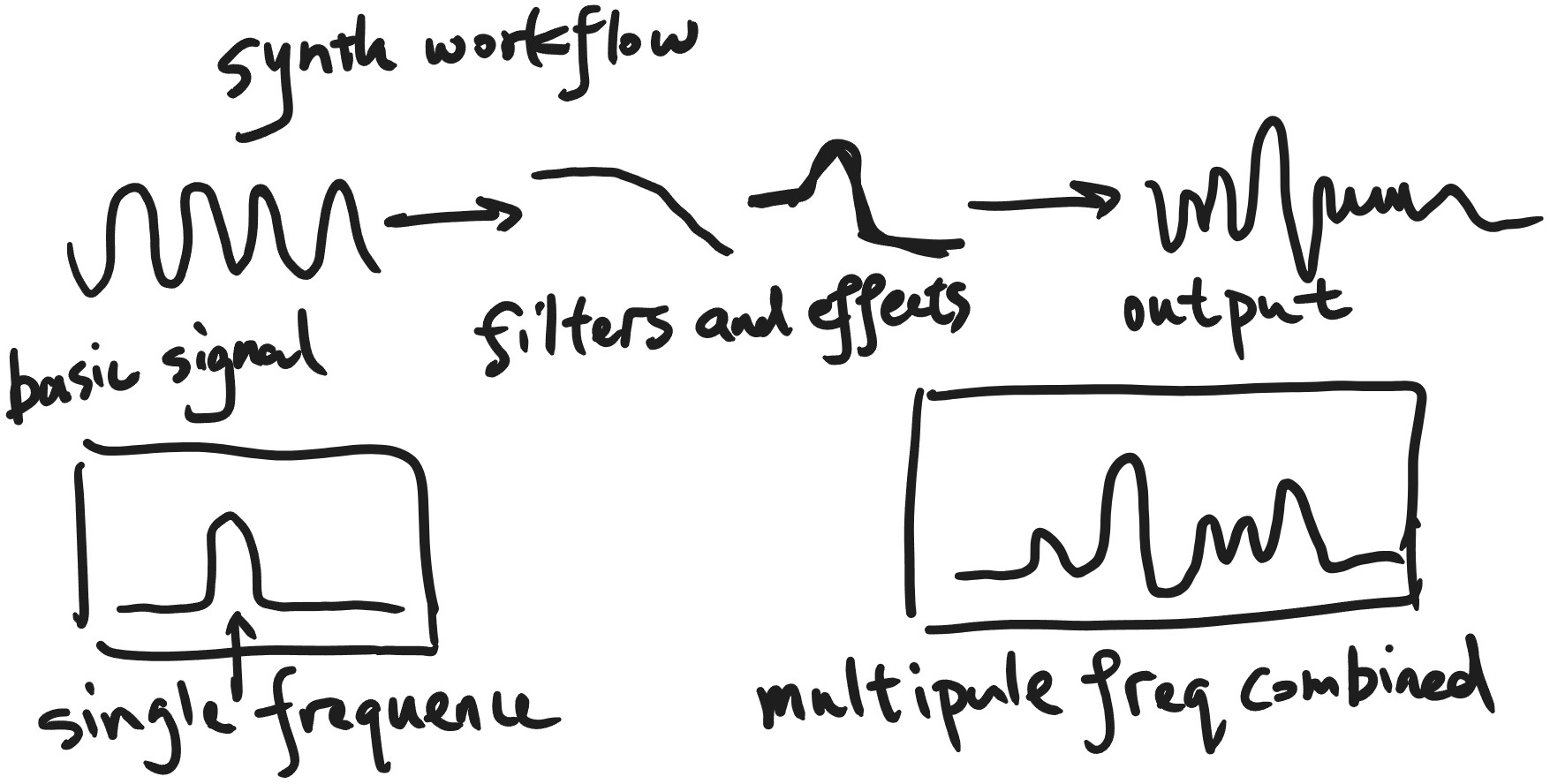
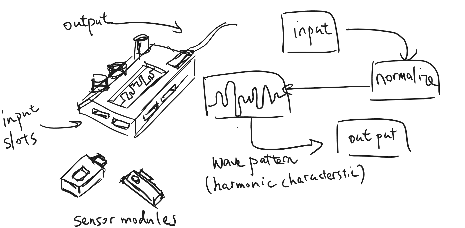
It's a device that can have slots for different inputs such as streams of the pitches of the music nodes, streams of different environmental senser data, etx. And it applies the filtering and transformation to the music signals or synthersizing new sounds based on the inputs from the sensors. The output signal may be output directly to the speaker or streamed to the computer for further processing.
And it has some knobs to adjust the operations' values and a screen to show informations to the user.
Early Verion 3D Model
The 3D model of an possible final project can be found here in week02.
Outputing Sound
I chose an ESP32 developement board as the microcontroller for the project becanse it has relatively good computing power to do the audio processing as well as the DAC to drive a speaker or the I2S interface that can communictate with other audio devices.
I first did some testing of outputing sound with the DAC pin directly and driving the speaker with a LM358P amplifier module.
It worked, but that requires maintaining the buffering and the timing of outputing sound data and adds much complexity to the code. So I also tried the MAX98357A I2S amplifier module, it uses the I2S interface and can drive small speakers up to 3 watts, which suits my need very well.
After I tested that it worked, I went on designing the PCB.
Components and PCB
As the project proceeds, I decided to save the idea of having multiple different sensor inputs later and have something that can interactive with the user first. So I settled on having a gyroscope and accelerometer module on the borad, which can provide multiple channels of input data for me to analyze.
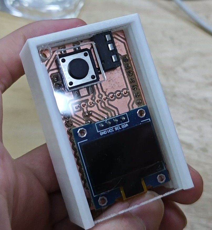
And I also put a small OLED screen for displaying some info, a touch button for control, and a headphone jack.
After I determined all the components that are needed, then it's the matter of having a PCB that holds all of them together.
Below is the final PCB I came up with.


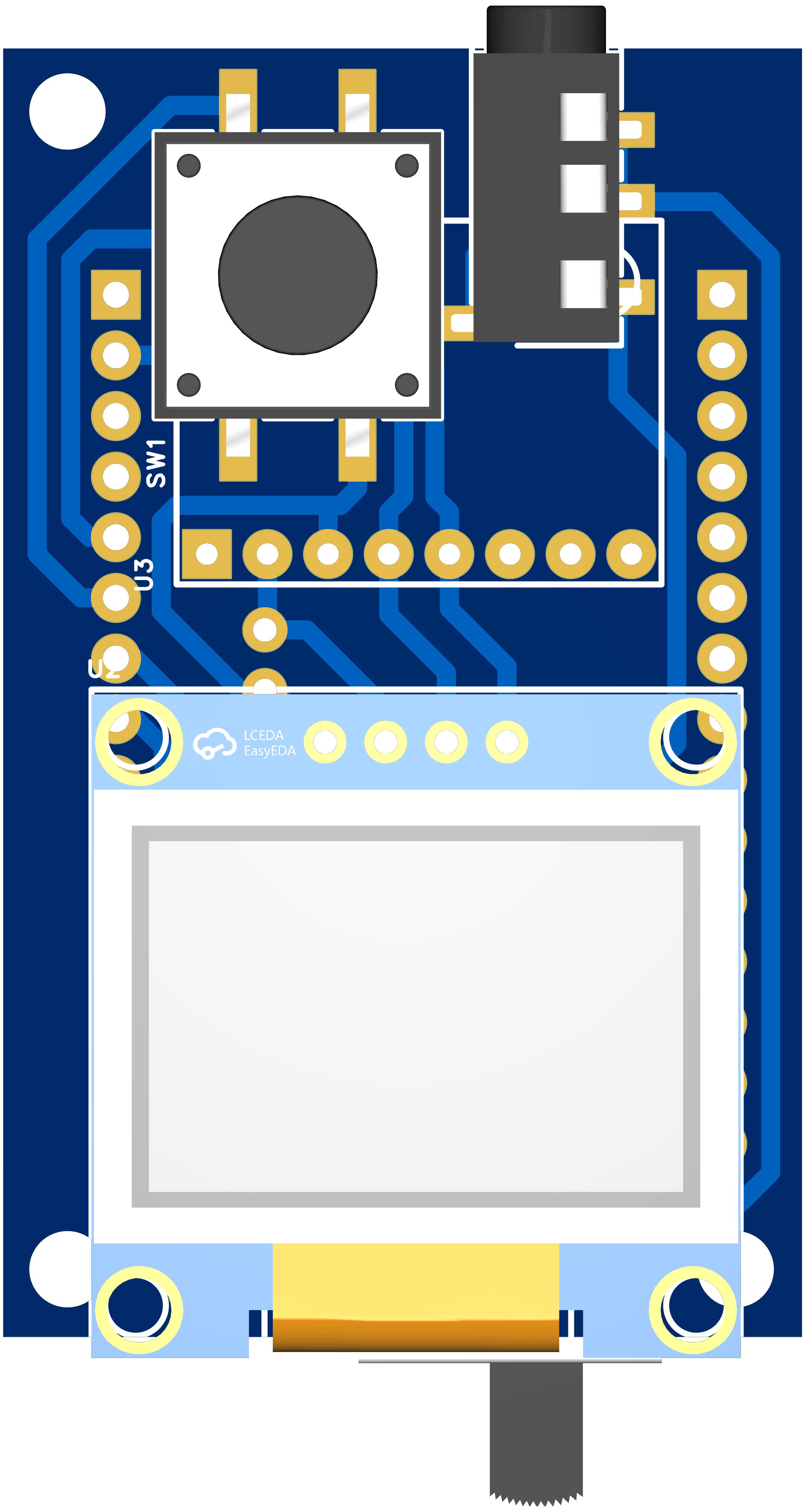
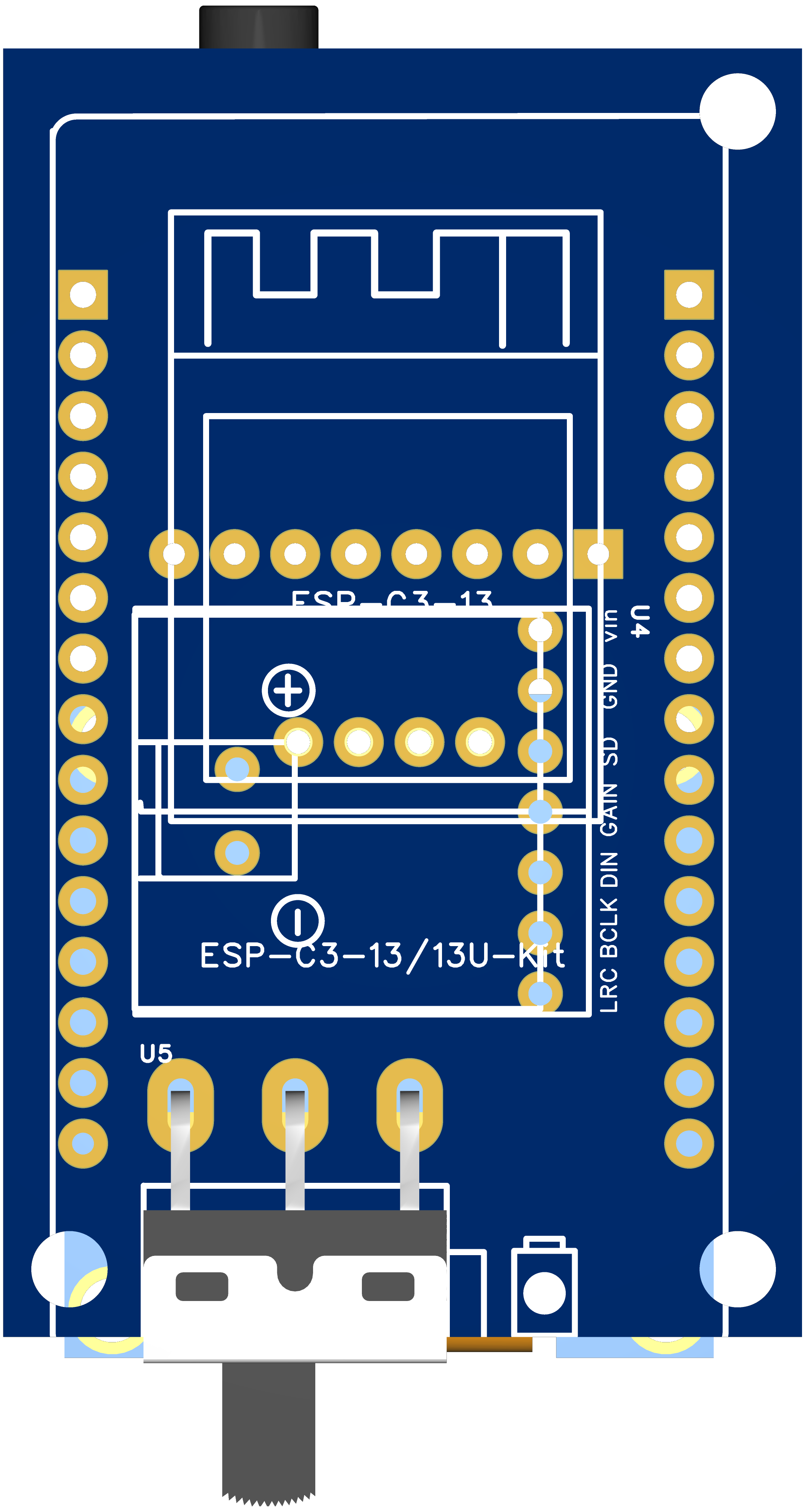
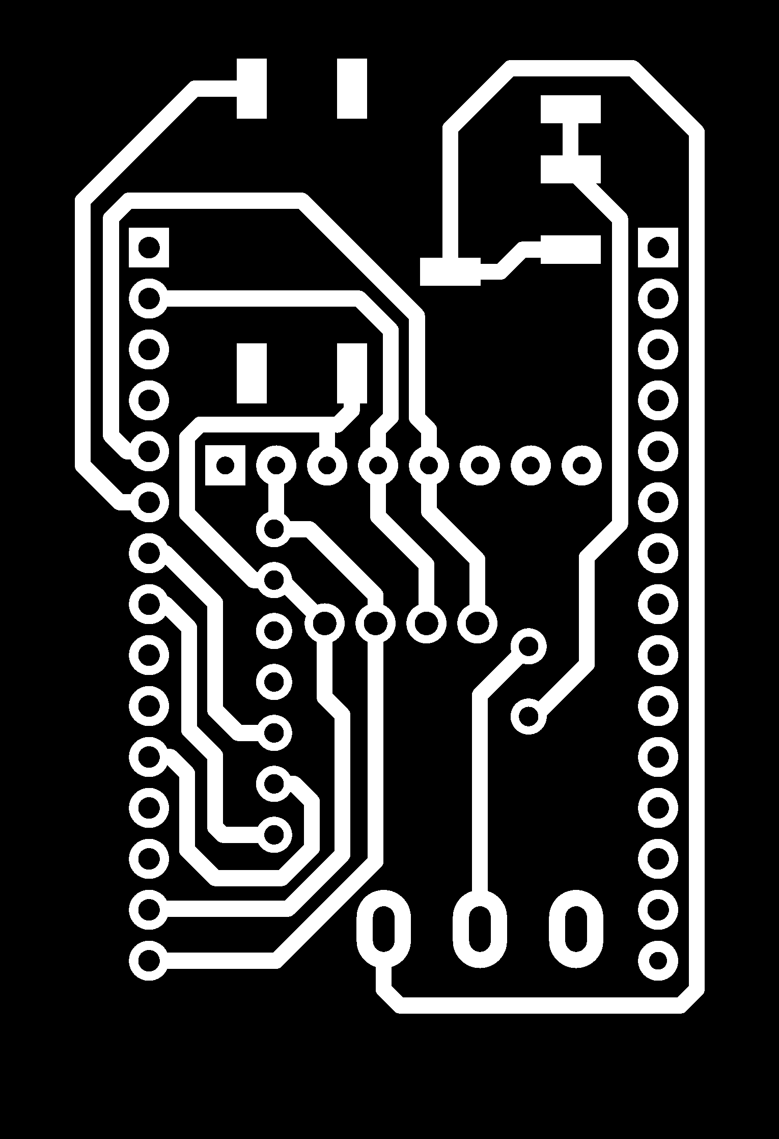
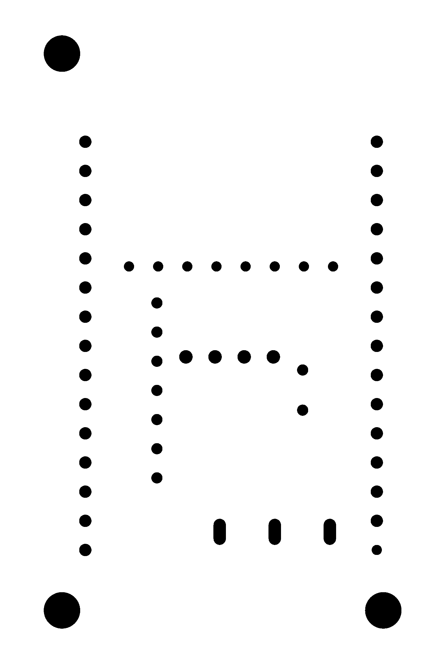

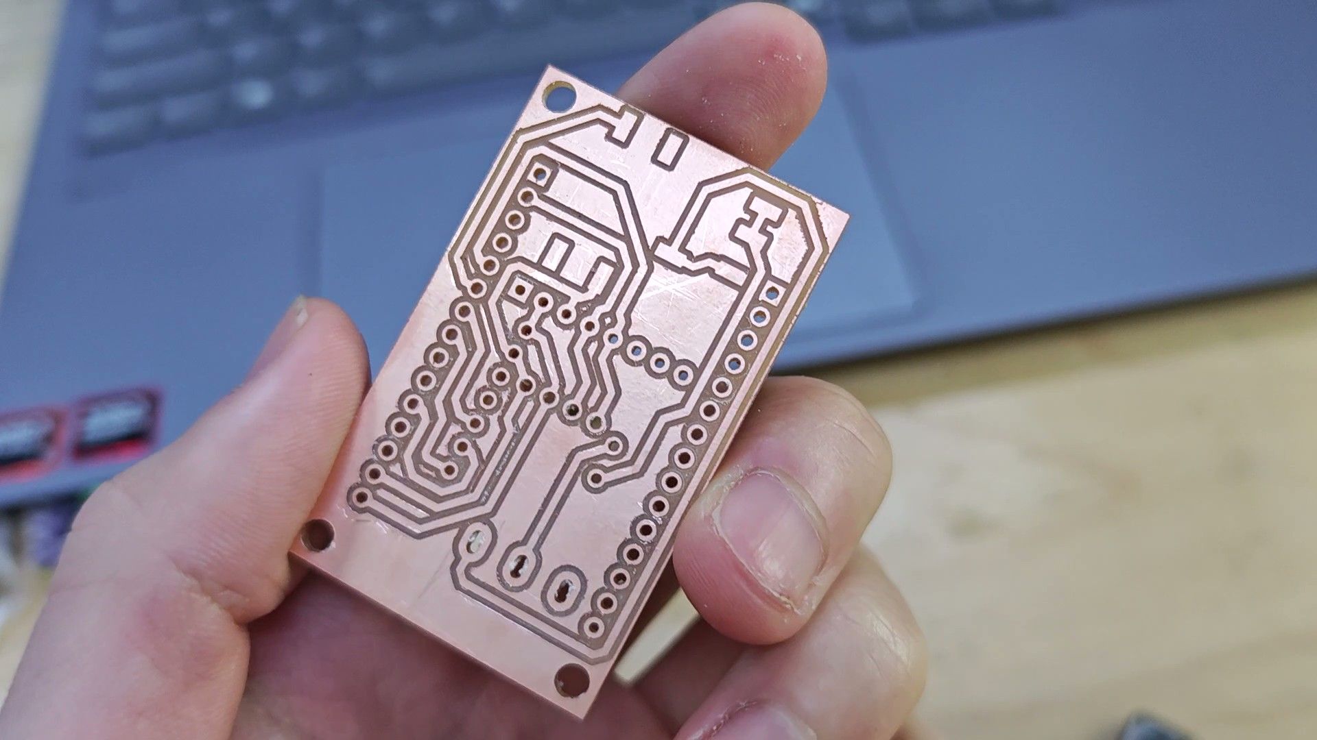
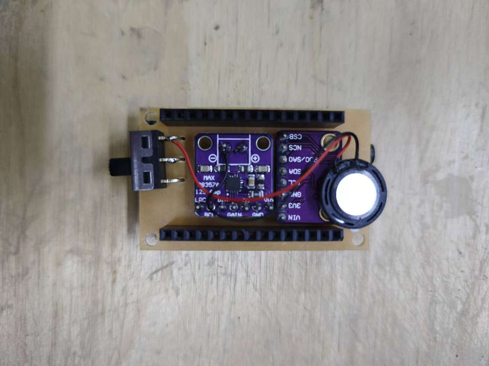
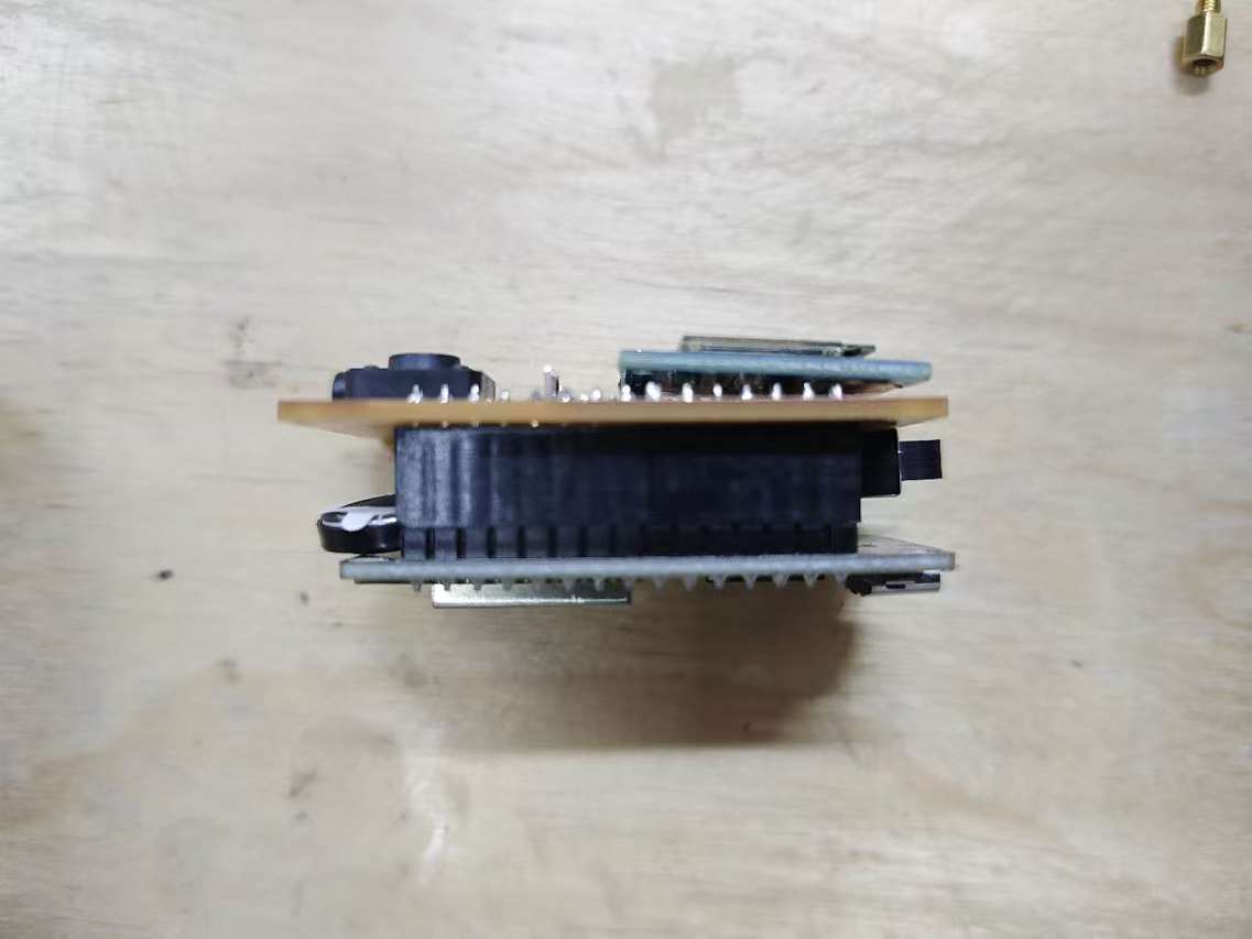
It's a compact board, there are the button, the screen and the headphone jack on the front, the accelerometer and the amplifier module are soldered on the back, along with a small speaker and a switch to switch between the outputs. The ESP32 development board is stacked on top of the modules when inserted into the pin headers.
Case
Then it's time to make a case for the device.
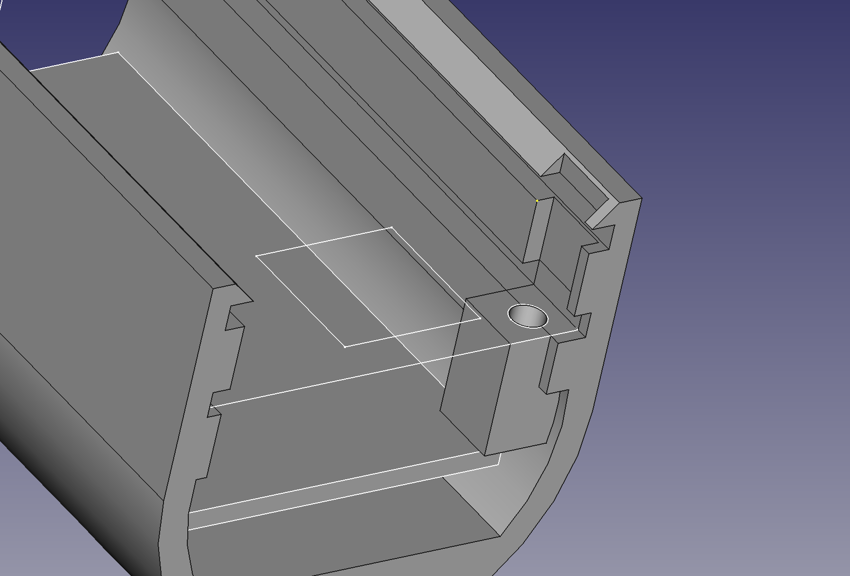
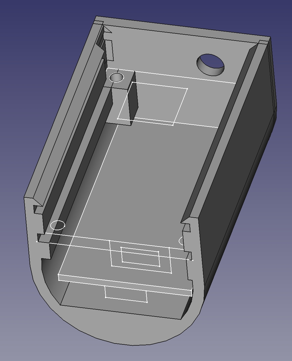
First I started sketching out the dimensions of the assembled PCB and DEV board in FreeCAD, using them as the reference for the case.
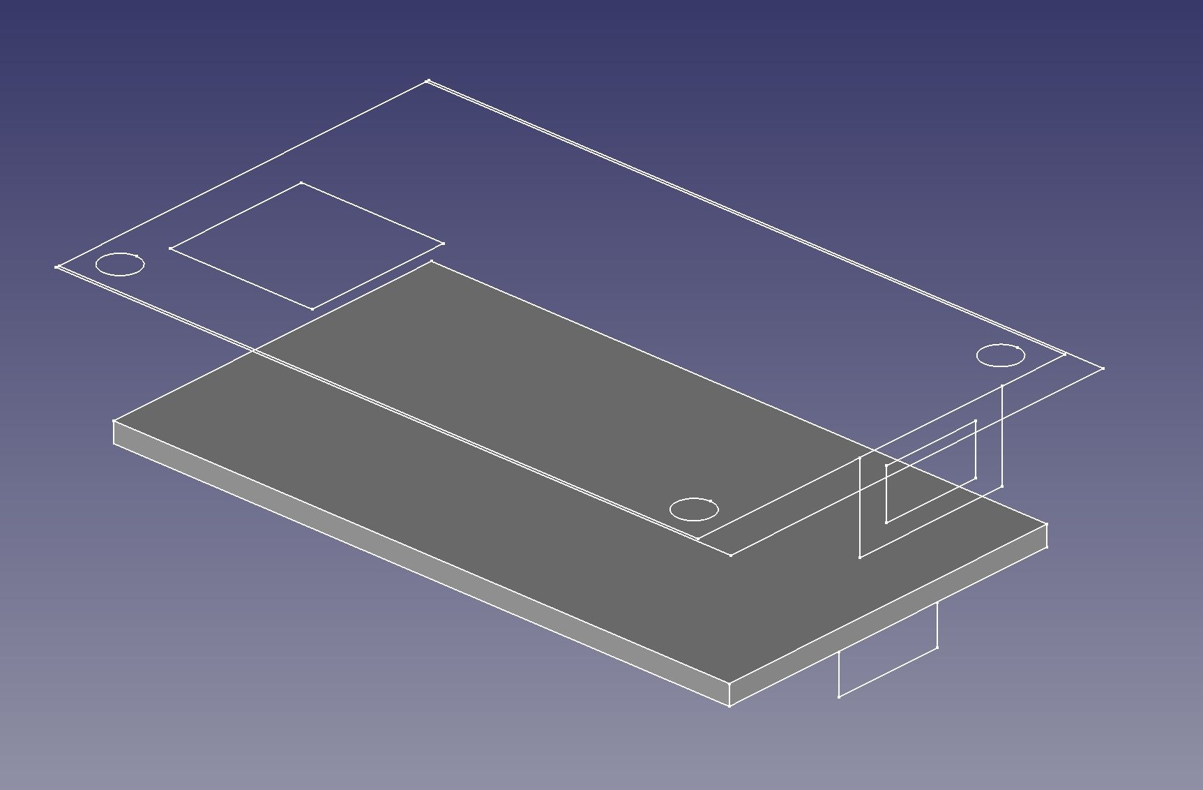
Then I sketched an outline of the case that sheilds all the interior and it has slots that can hold the PCB and the front panel in place, extrude and the main structure is done.
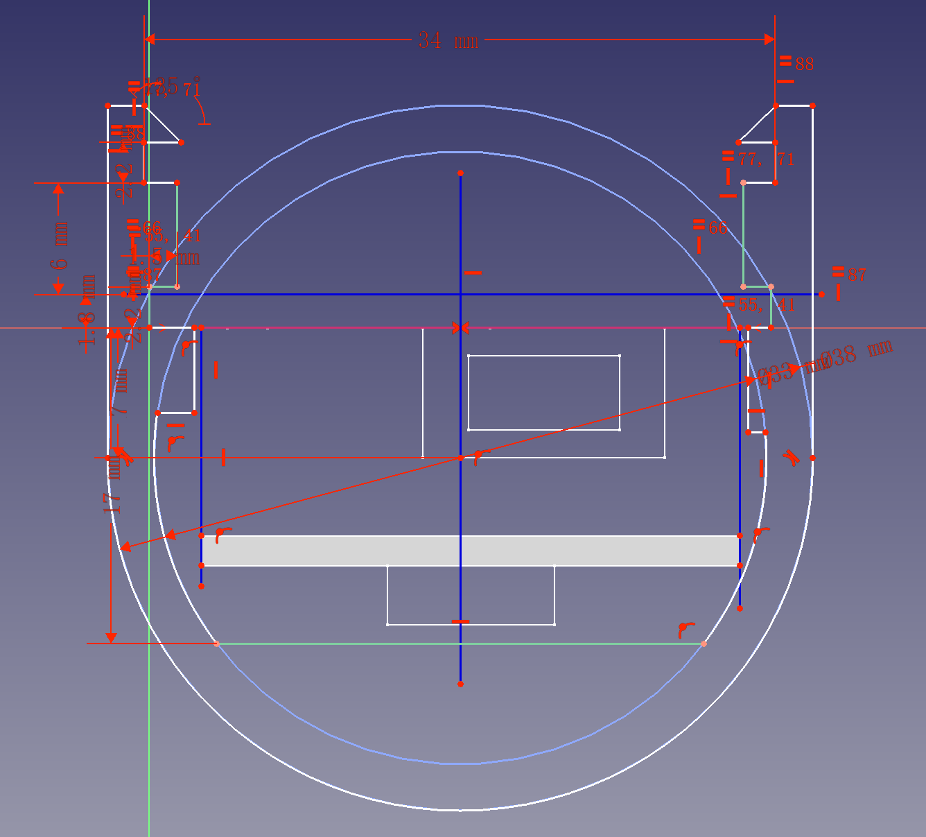
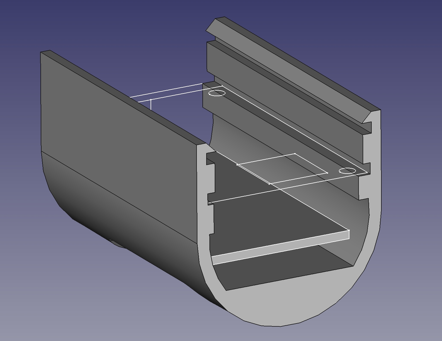
Then add the place for a screw to keep the PCB in place, and close off the top leaving the hole for the headphone jack.
 p
p
The final 3D printed case is like this.
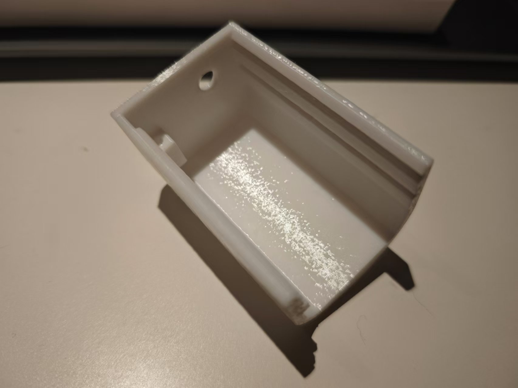
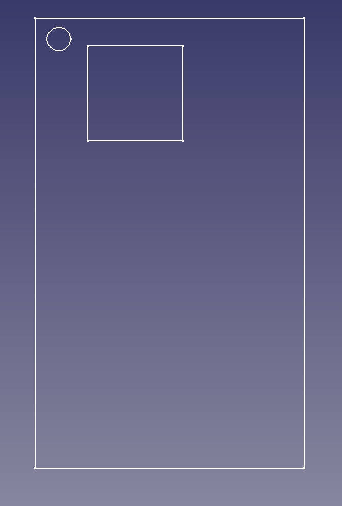
Then cut an acrylic panel with the lasercutter and we have all the parts we need.
Below is the devices fully assembled.
BOM
Here's the bill of matrerial for the project:
| Item | Cost (¥) |
|---|---|
| ESP32 Dev Module | 19.82 |
| GY91 accelerometer and gyro scope module | 15.1 |
| MAX98357 I2S amp module | 5.65 |
| 8Ω 1W speaker module 15mm | 2.69 |
| SS12D11 G5 switch 3 pin | 0.97 |
| PJ-320D 3.5mm headphone jack SMD | 0.48 |
| SMD Button 12x12x5 | 0.15 |
| 0.96inch I2C OLED screen | 8.8 |
| 2X 15P female pin headers | 0.48 |
| FR1 single side copper clad laminate 15x20cm | 10.29 |
| PLA 3D print filament 18.3g | 0.74 |
| Trasparent Acrylic 50x100x2mm | 0.19 |
| M3 Copper stand 6mm | 0.07 |
| Screw M3x4mm | 0.02 |
| Total | 65.45 |
Program
Build and upload with Arduino IDE.
- Board: ESP32 Dev Module
Library Dependencies
Install from the Arduino library manager.
Source Code
#include <ESP_I2S.h>
#include <U8g2lib.h>
#include <MPU9250.h>
#include <FastTrig.h>

#define ARRAY_LEN(arr) (sizeof(arr)/sizeof *(arr))

const int button_pin = 19;
const int sample_rate = 16000; // sample rate in Hz

// frequency values for notes
const float E2  = 82.41;
const float F2  = 87.31;
const float G2  = 98;
const float A2  = 110;

const float AS4 = 466.16;
const float B4  = 493.88;
const float C5  = 523.25;
const float CS5 = 554.37;
const float D5  = 587.33;
const float FS5 = 739.99;

struct input_buffer {
  static const int value_count = 200;
  int write_p;
  float values[value_count];
};

// structure that stores the infos about the notes being played
struct mixer {
  struct note {
    float frequency;
    float start_time;
    float duration;
    float amplitude;
  };

  static constexpr float attack   = 0.1f;
  static constexpr float release  = 0.2f;
  // the amount of the note's amplitude is being ramped up every sample during attack
  static constexpr float up_val   = 1.0f / attack / sample_rate;
  // the amount of the note's amplitude is being turned down every sample during release
  static constexpr float down_val = 1.0f / release / sample_rate;

  static const int note_count = 10;
  note notes[note_count];

  uint64_t sample_count = 0;
  float dt;
};

inline float fraction(float f) { return f - (int)f; }

// sin function in turns
// isin() is the optimized version of sin() from the FastTrig library
inline float tsin(float t) { return isin(360*t); }

inline void push_value(input_buffer *input, float val) {
  input->values[input->write_p++] = val;
  if (input->write_p >= input->value_count)
    input->write_p = 0;
}

inline float get_sample_value(input_buffer *input, float a /* 0..1 */) {
  return input->values[(size_t)(fraction(a) * input->value_count)];
}

inline float get_semetrical_value(input_buffer *input, float a /* 0..1 */) {
  return input->values[(size_t)((1.5f - a) * input->value_count + input->write_p) % input->value_count];
}

inline float get_circular_value(input_buffer *input, float a /* 0..1 */) {
  return input->values[(size_t)(a * input->value_count + input->write_p) % input->value_count];
}

void mixer_add_note(mixer* m, float frequency, float duration) {
  for (mixer::note& n: m->notes) {
    float played = m->dt - n.start_time;
    if (played > n.duration + m->release) {
      n.frequency = frequency;
      n.duration = duration;
      n.amplitude = 0;
      n.start_time = (float)m->sample_count/sample_rate;
      return;
    }
  }
  Serial.println("No free note avaliable in the mixer.");
}

float mix_one_sample(mixer* m, input_buffer buffers[], int buffer_count) {
  m->dt = (float)m->sample_count++ / sample_rate;

  int buffer_idx = 0;
  float value = 0;
  for (mixer::note& n: m->notes) {
    float played = m->dt - n.start_time;
    if (played > n.duration + m->release) continue;

    if (played > n.duration)
      n.amplitude -= m->down_val;
    else if (m->dt > n.start_time && played < m->attack)
      n.amplitude += m->up_val;

    n.amplitude = std::clamp(n.amplitude, 0.0f, 1.0f);
    float val = get_sample_value(&buffers[buffer_idx], n.frequency * m->dt) * n.amplitude;
    ++buffer_idx %= buffer_count;
    value += val;
  }

  return value;
}

// Global variables
I2SClass i2s;
U8G2_SSD1306_128X64_NONAME_F_HW_I2C u8g2(U8G2_R0);
MPU9250 mpu; // ESP32 I2C pins: SDA - 21, SCL - 22

bool mute = false;
float volumn = 0.1;

mixer m = {};
input_buffer buffers[6] = {};

void task_i2s_audio(void *param) {
  const int i2s_bclk_pin = 4;
  const int i2s_ws_pin   = 5;
  const int i2s_dout_pin = 18;
  i2s.setPins(i2s_bclk_pin, i2s_ws_pin, i2s_dout_pin);
  i2s_mode_t mode = I2S_MODE_STD;
  i2s_data_bit_width_t bits_per_sample = I2S_DATA_BIT_WIDTH_32BIT;
  i2s_slot_mode_t slot_mode = I2S_SLOT_MODE_STEREO;
  if (!i2s.begin(mode, sample_rate, bits_per_sample, slot_mode)) {
    Serial.println("Failed to initialize I2S!");
    while (1) ; // do nothing
  }

  for (;;) {
    float amplitude = mute ? 0 : INT32_MAX * volumn;
    float value = mix_one_sample(&m, buffers, ARRAY_LEN(buffers));
    value *= amplitude;
    int32_t sample[2] = {(int32_t)value, (int32_t)value};
    i2s.write((uint8_t *)sample, sizeof(sample));
  }
}

void setup() {
  Serial.begin(115200);
  Serial.println();
  Serial.printf("setup() running on core %d\n", xPortGetCoreID());

  pinMode(button_pin, INPUT_PULLUP);

  u8g2.begin();
  u8g2.setFont(u8g2_font_ncenB08_tr);	// choose a suitable font

  if (!mpu.setup(0x68)) {
    Serial.println("MPU connection failed.");
    while (1);
  }

  // generate and output audio samples on another core
  TaskHandle_t i2s_task;
  xTaskCreatePinnedToCore(task_i2s_audio, /* Task function. */
                          "I2S Audio",    /* name of task. */
                          10000,          /* Stack size of task */
                          0,              /* p=arameter of the task */
                          0,              /* priority of the task */
                          &i2s_task,      /* Task handle to keep track of created task */
                          0);             /* pin task to core 0 */
}

void loop() {
#define INTERVAL(ms) for (static unsigned long last_time; last_time == 0 || millis() > last_time + (ms); last_time = millis())

  int button_state = digitalRead(button_pin);

  // read accelerometer every 10 milliseconds if the button is pressed
  INTERVAL(10)
  if (button_state == 0 && mpu.update()) {
    push_value(&buffers[0], mpu.getYaw() / 180.0f);
    push_value(&buffers[1], mpu.getPitch() / 90.0f);
    push_value(&buffers[2], mpu.getRoll() / 180.0f);
    push_value(&buffers[3], mpu.getAccX() / 3.0f);
    push_value(&buffers[4], mpu.getAccY() / 3.0f);
    push_value(&buffers[5], mpu.getAccZ() / 3.0f);
  }

  // push the next note to the mixer every 250 seconds
  INTERVAL(250) {
    static const float sequence[] = {AS4, C5, CS5, FS5};
    // static const float sequence[] = {B4, CS5, D5, FS5};
    static int idx = 0;
    mixer_add_note(&m, sequence[++idx%4], 0.2);
  }

  // update screen every 100 milliseconds
  INTERVAL(100) {
    u8g2.clearBuffer();
    if (button_state == 0) u8g2.drawStr(5, 20, "Sampling Inputs");
    for (int x = 0; x < u8g2.getWidth(); ++x) {
      for (int i = 0; i < 3; ++i) {
        int idx = (float)x / u8g2.getWidth() * buffers[i].value_count;
        int y = (1 - (buffers[i].values[idx] + 1) / 2) * (u8g2.getHeight() - 1);
        u8g2.drawPixel(x, y);
      }
    }
    u8g2.sendBuffer();
  }

}
Project files
- PCB schematics: schematics.png
- PCB milling files:
- traces: synth_traces.png
- holes: synth_holes.png
- outline: synth_outline.png
- Case FreeCAD project file: case.FCStd
- Case 3D model: case.step
- Front panel: case-front-panel.dxf
- Arduino source code: dynamic-synth.ino