2. Computer-Aided Design
This week we starts exploring some different tools for doing computer-aided design.
Assignment
- Model (raster, vector, 2D, 3D, render, animate, simulate, ...) a possible final project, compress your images and videos, and post it on your class page
Learn FreeCAD
As a product designer, I have had come exprience in 3D modeling and rendering, mostly in Blender. Blender is a great tool for doing polygonal modeling and 3D animation rendering. Though it has a non-destructive modifier workflow, there's not very much parametric aspect to it, and due to it's polygonal nature, it's not very convenient to model 3D parts for digital frabrication.
On this week's class, Neil introduced lots of different CAD softwares and used FreeCAD as an example to illustrate many useful techniques that we can do using the parametric workflow. I'm excited to try out the new way to do 3D design, and I started with FreeCAD first to do it.
I went to the offical website of FreeCAD and got a portable download for windows, then I followed a video tutorial on youtube to learn the basics of FreeCAD. I have not settled with my final project idea now so I'll document my learning process first.
FreeCAD has lots of tools and its user interface is a little bit intimidating at first. But it all makes sense after I learned the basics and it's modeling workflow.
The Part Design Workbench
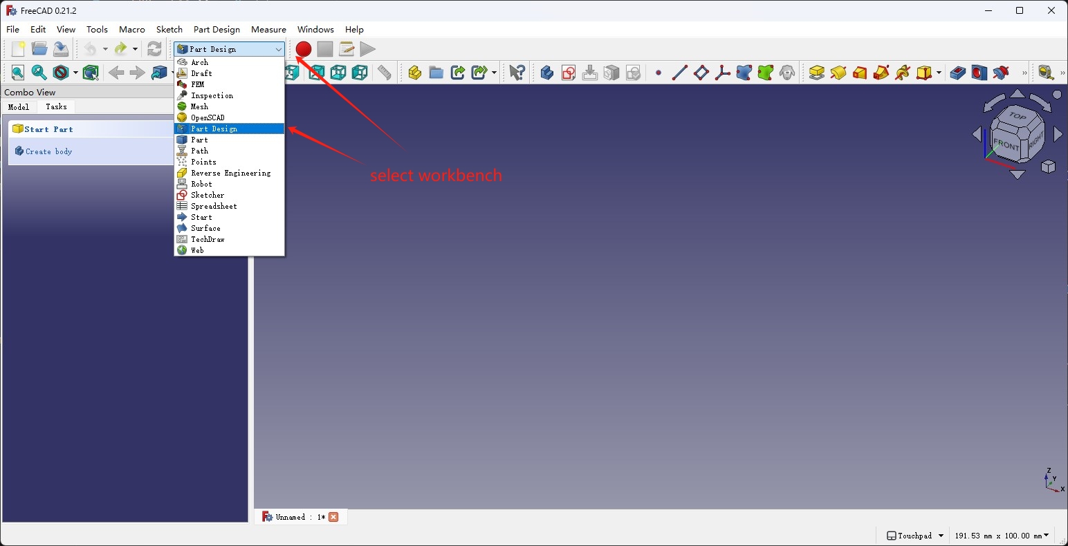
FreeCAD groups its tools into different workbenches based on the workflow that is used, for 3D parts modeling, we need to use its Part Design workbench.
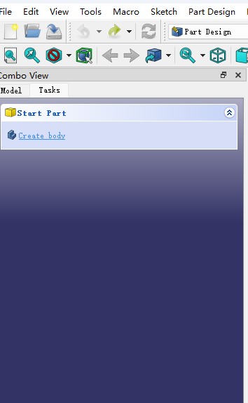
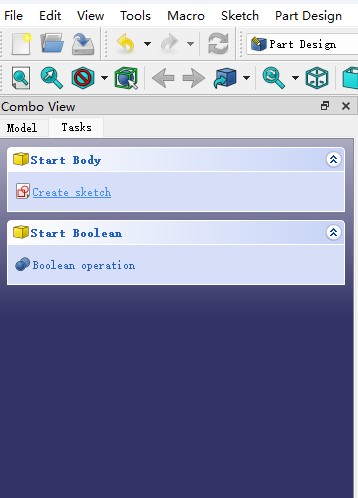
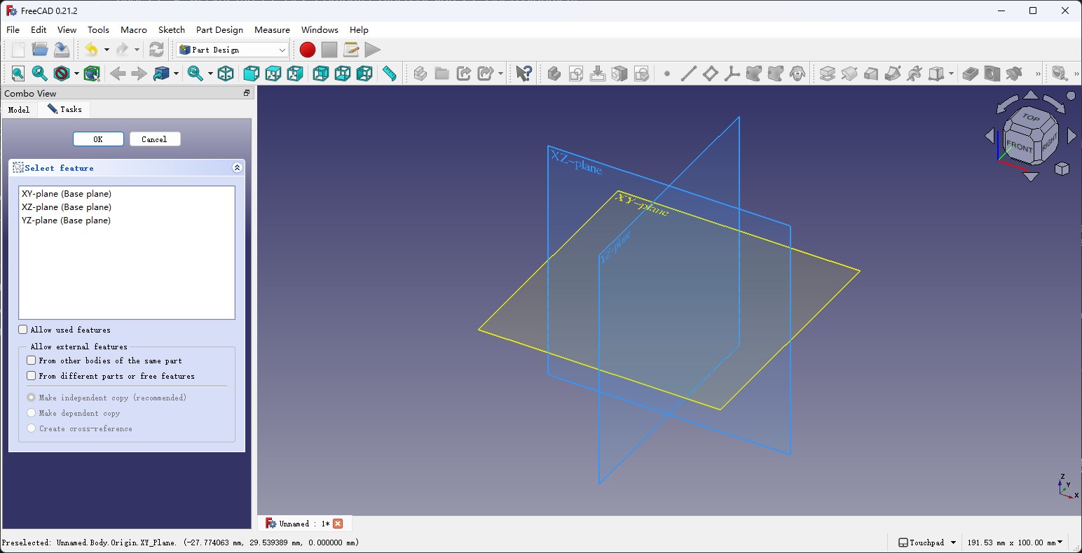
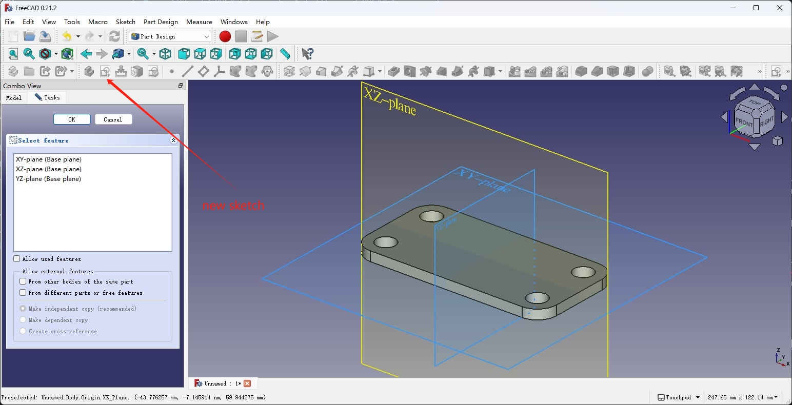
We can select it from the dropdown menu in the middle and from the Task tab on the left, it shows that we need to create an body and a sketch. After clicking the Create sketch button, it lets us pick a plane that we want to work in.
Now we've entered the sketcher workbench and we have the tools to make the 2D sketch of our parts in the toolbar. We have to create the geometries with the create tools and then use the constrain tools to constrain the shapes to make the sketch. It's logic is different from the softwares I have used but it's very powerful after I got used to it.
I'm working in the XY-plane so I'm sketching out the part from the top view.
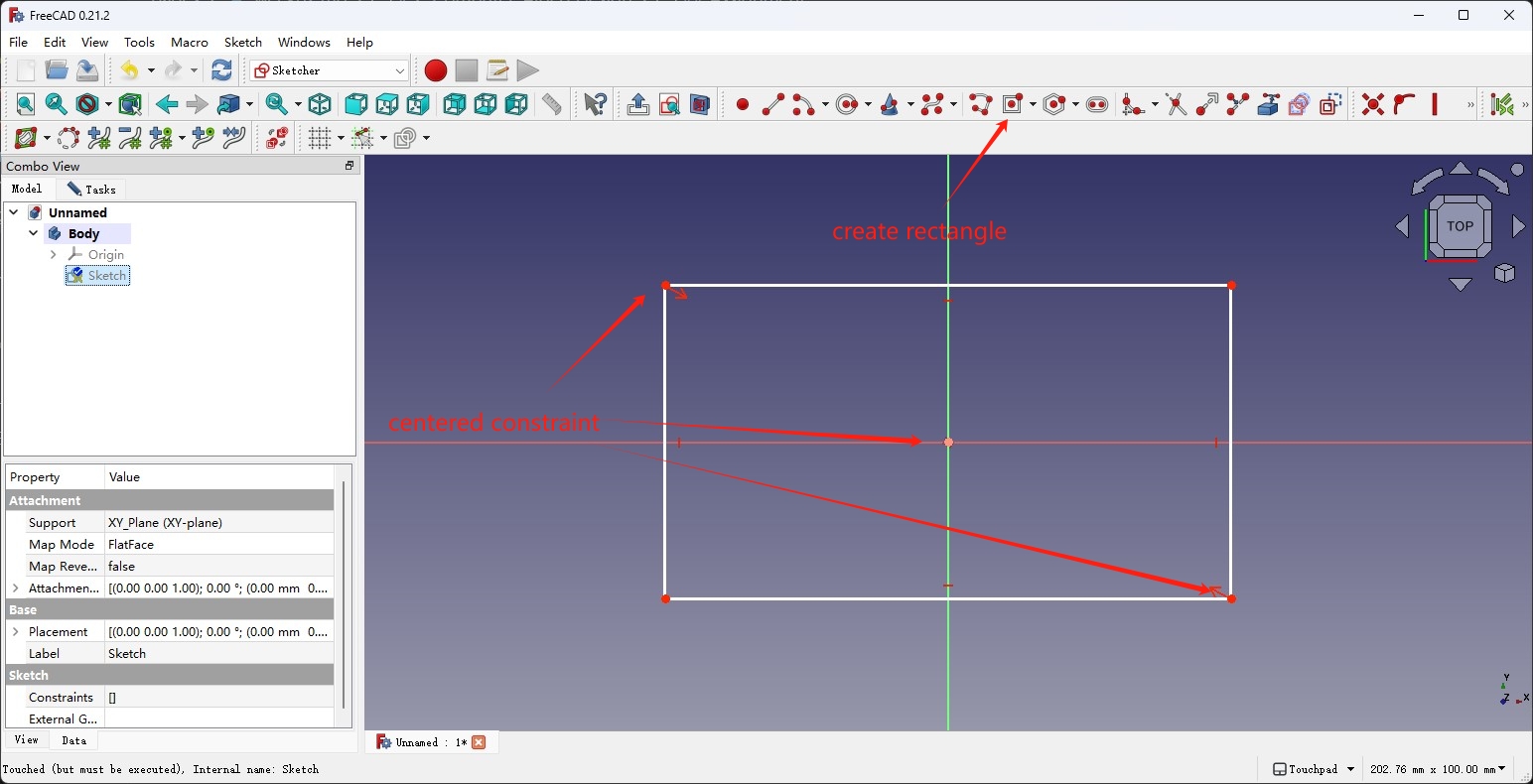
First, use the centered rectangle tool to create a rectangle that is centered at the center point of the sketch, the center point is automaticly constraint to the center of the sketch.
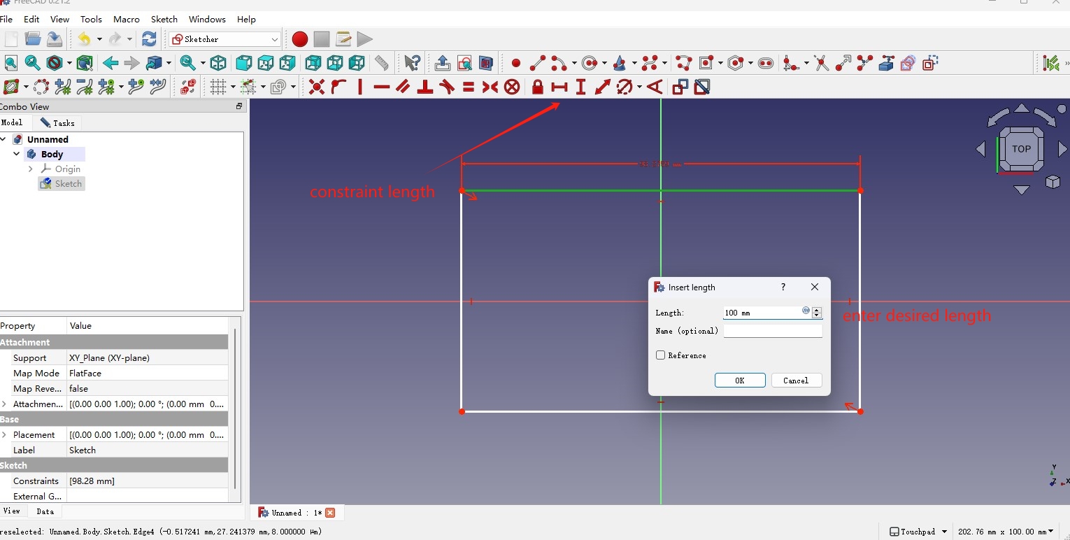
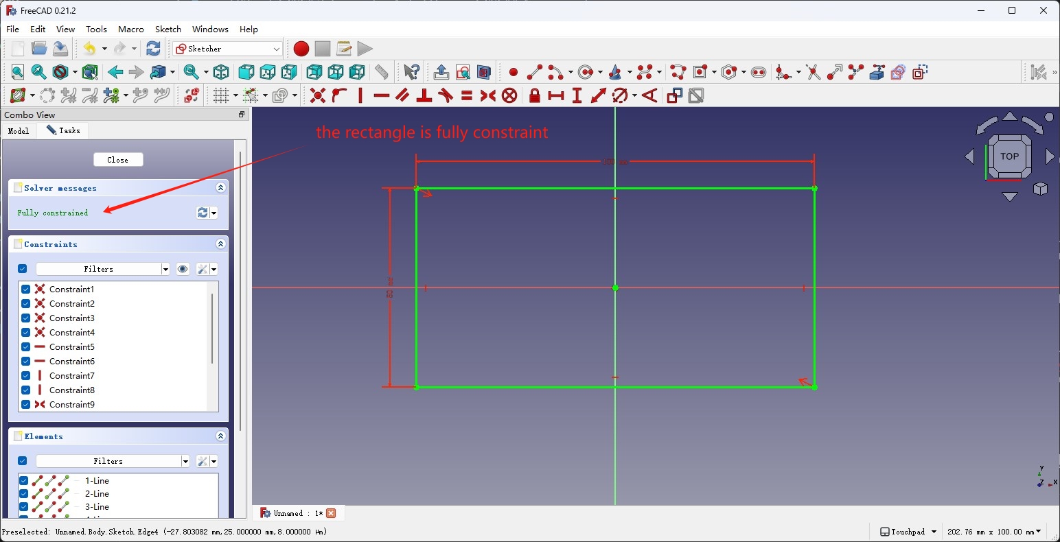
Then we can use the constrain vertical distance and constrain horizontal distance tools to constrain the two dimention of the rectangle. After that, the sketch turned green and the left Tasks tab showed that the sketch now is Fully constrained and the edges of the rectangle cannot be moved afterwards.
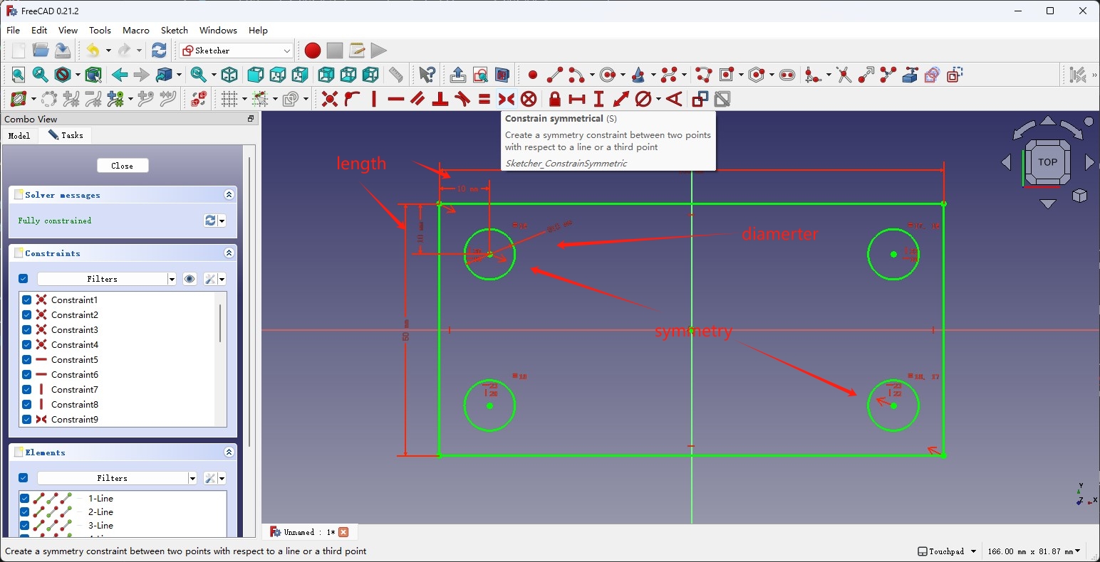
Then I used the create circle tool to create four circles in the corner of rect, and alse used the constrain tools to constrain the vertical and horizontal positon, as well as the diameter of the circles. The parametric workflow allow me to use the constrain equal tool to make the circles all have the same size and postiion full constrained.
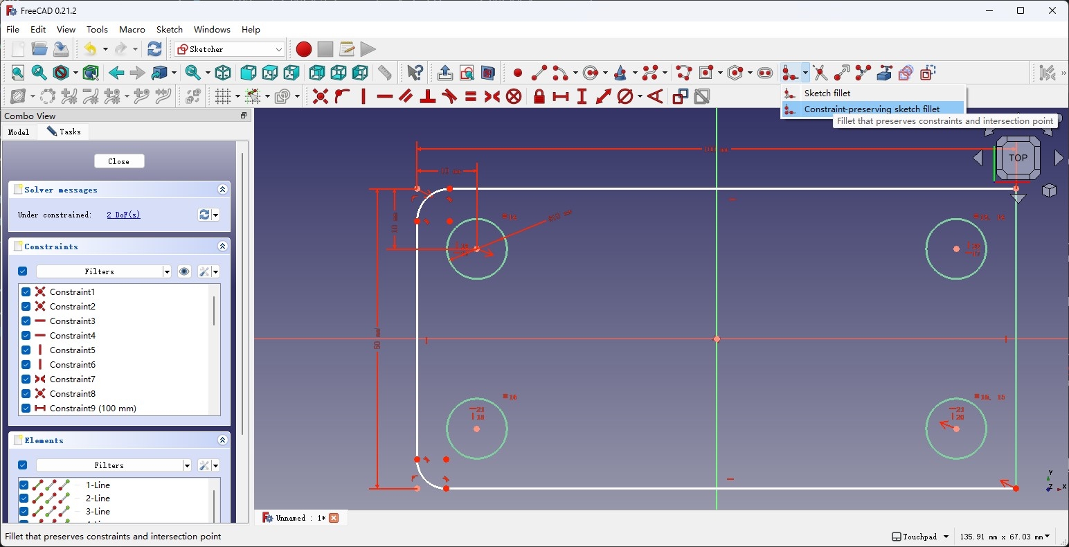
Then I used the constaint-preserving sketch fillet tool to add fillets to the four corners of the rectangle. Then I went on adding the coincident constraint to the center of the arc to make them use the same center as the corner circles, and the sketch turned orange and the solver on the left shows that the sketcth now is over constraint. By clicking the number on the right, FreeCAD selects and highlights the constrint that is redundant in the viewport and it's the constraint of the arc itself was colliding with the the coincident constraint.
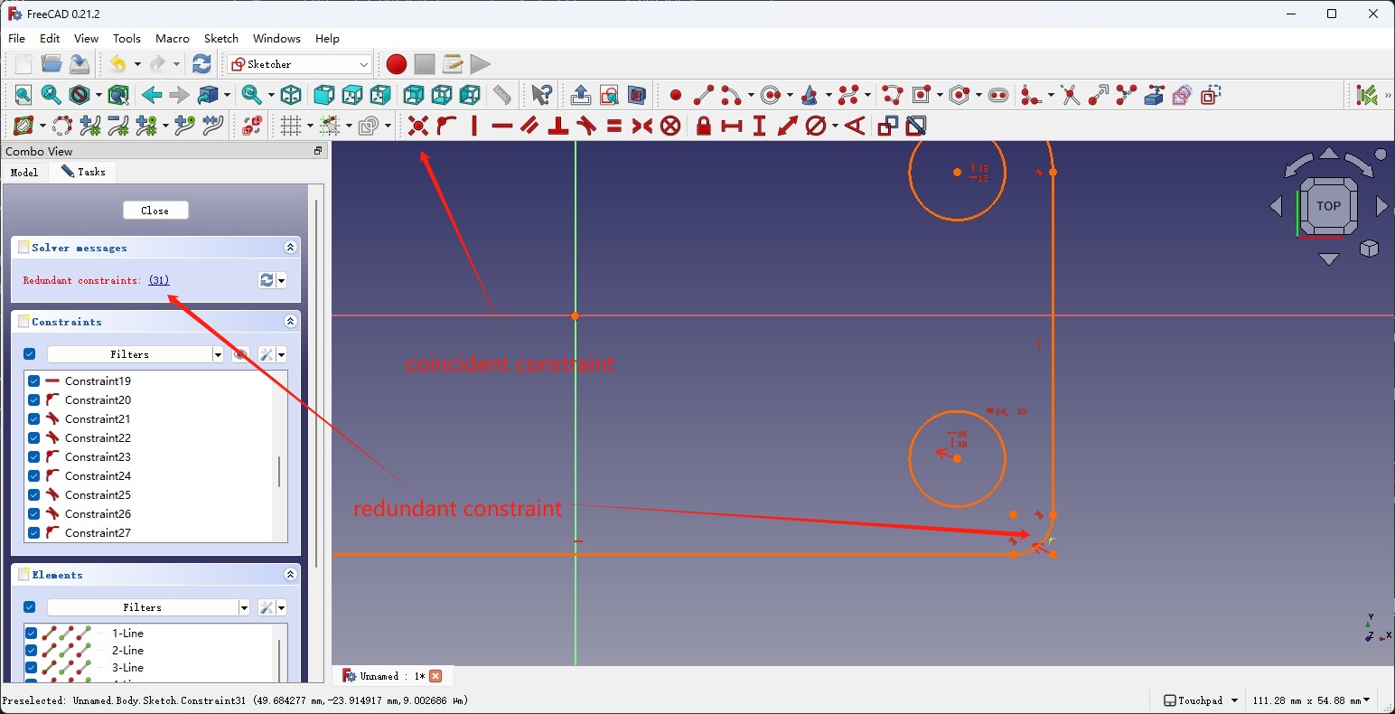
Pressing the delete key just deletes the redundant constraint and the sketch is now fully constraint again.
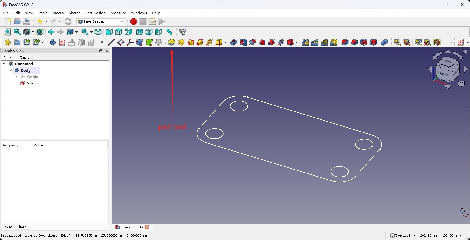
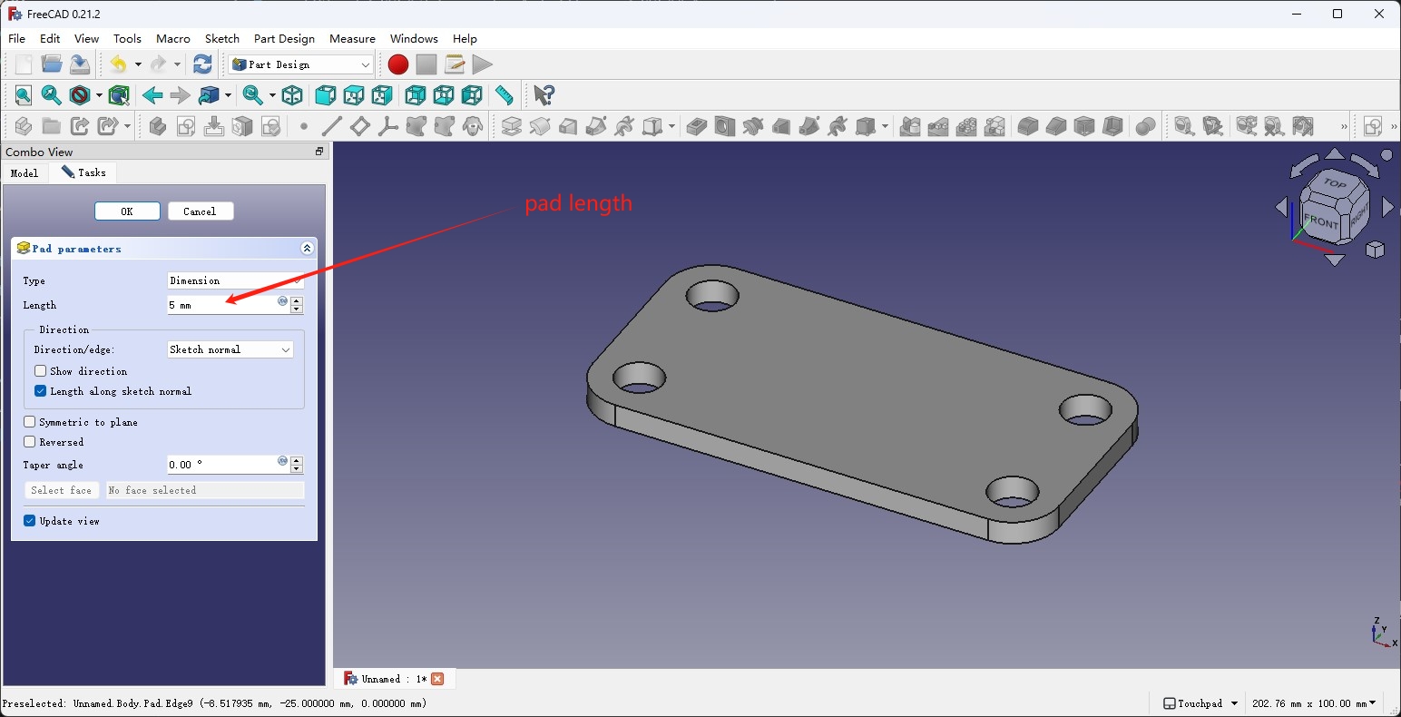
Now press the Ok button on the left brings us out of the sketcher workbench, and we can use the Pad tool in the Part design workbench to pad the sketch that we made to create a solid object. The padded length can be adjusted using the parameters on the left.
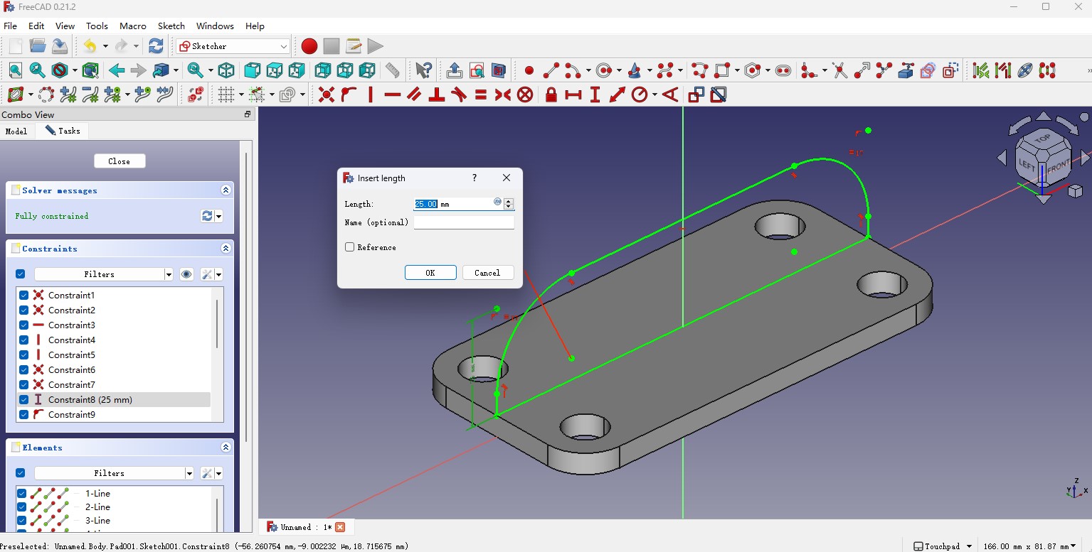
Then click the create sketch button again to create another sketch, this time I selected the XZ-plane to sketch from the front view.
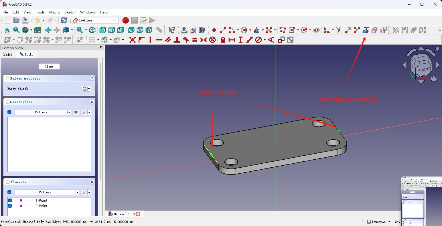
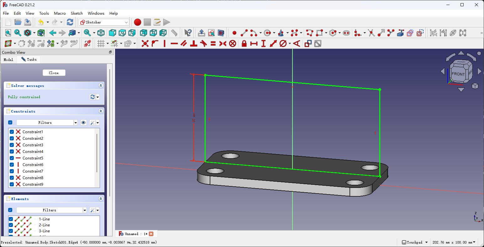
First use the create external geometry tool to select the two edges on the top surface to get the two intersecting points with the plane, then they can be used to constrain the rectangle that we made.
Also add fillets to the corners.
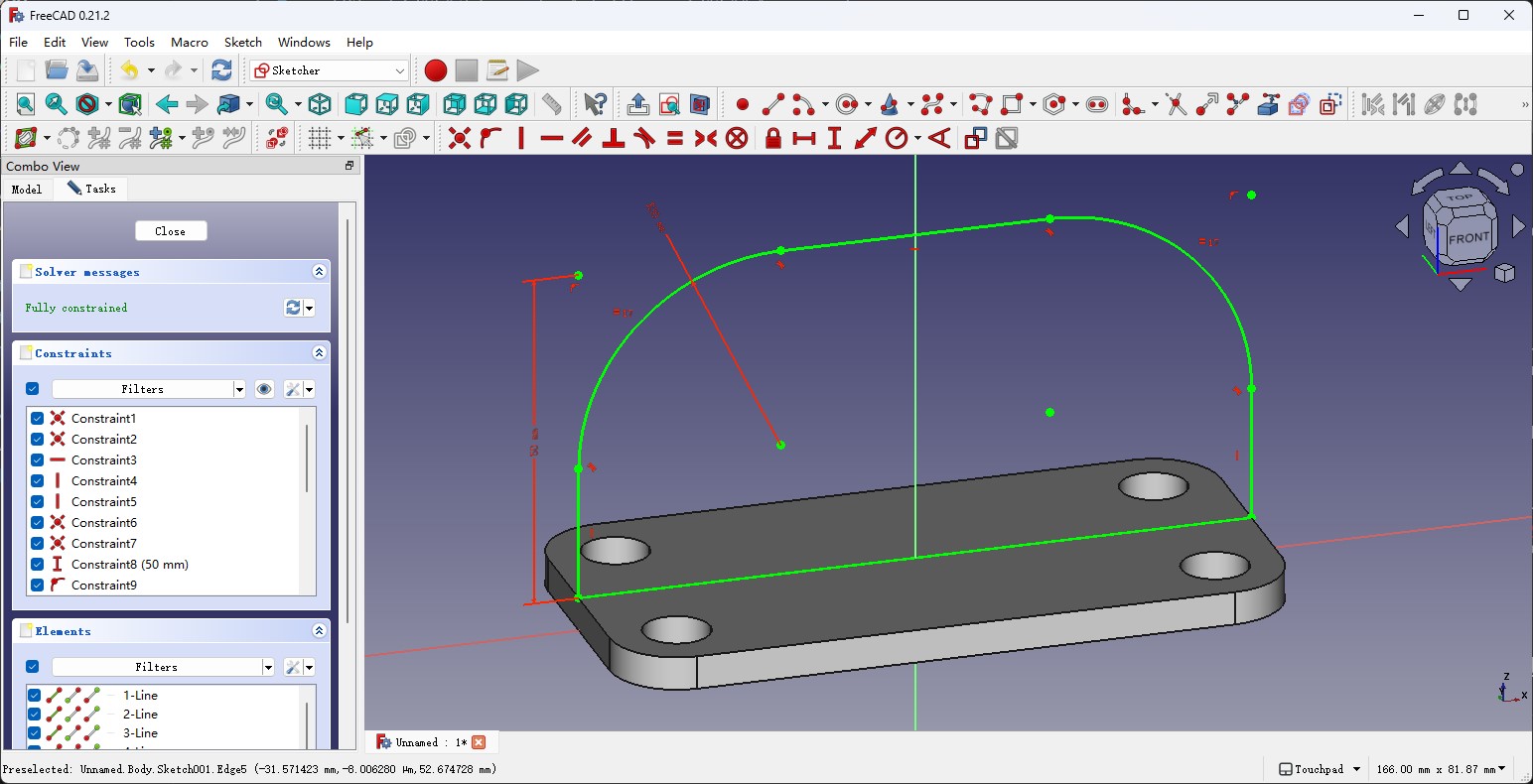
Use the pad tool again to create the solid from the sketch, check the Symmetric to plane checkbox to make it centered on the top.
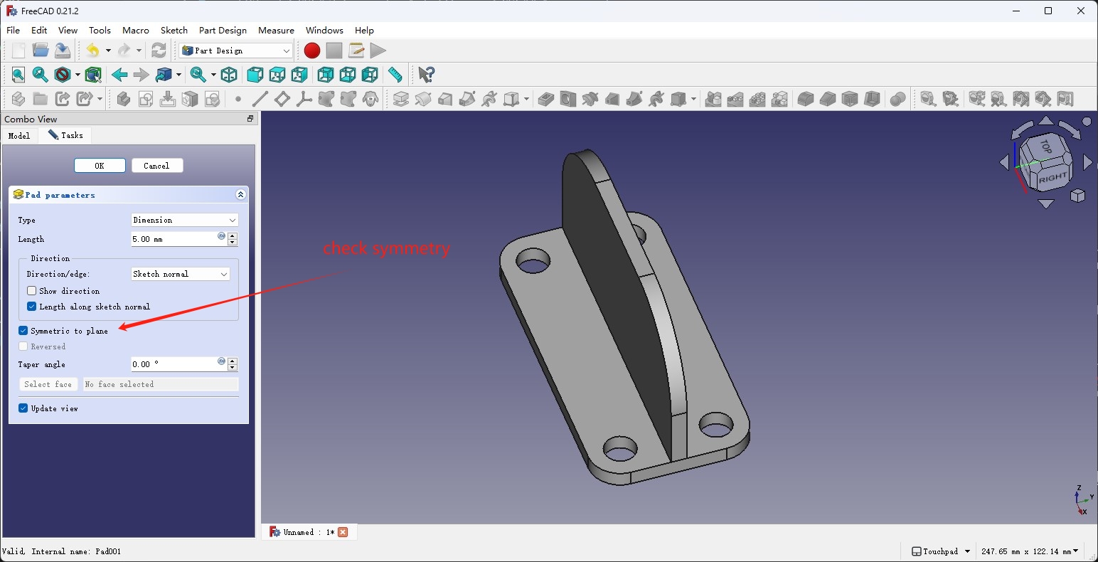
I found the length of the top part is not ideal, so I went into the sketch that defines the constraint and changed the parameter, the change is also reflected on the padded object.
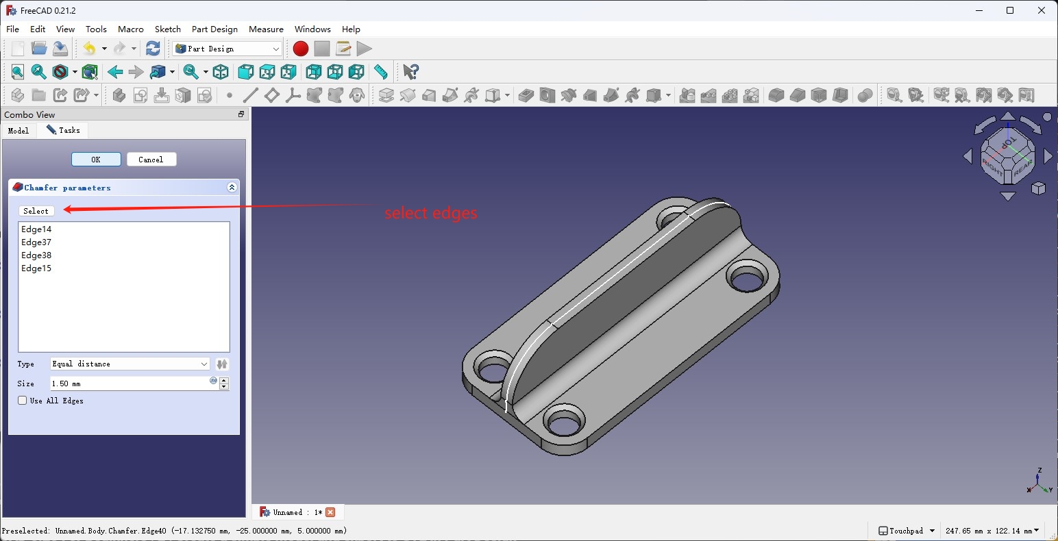
Also in the Part Design workbench, there are fillet and chamfer tools to create them directly on the body. Select the tool and on the left tasks tab, I can add the edges I wanted to chamfer and fillet and adjust the size parameters.
The TechDraw Workbench
After I finished the model, I can use the TechDraw workbench to generate the technical drawing of the model I have.
First, select the TechDraw workbench from the dropdown menu, and click the insert default page button to create a new page.
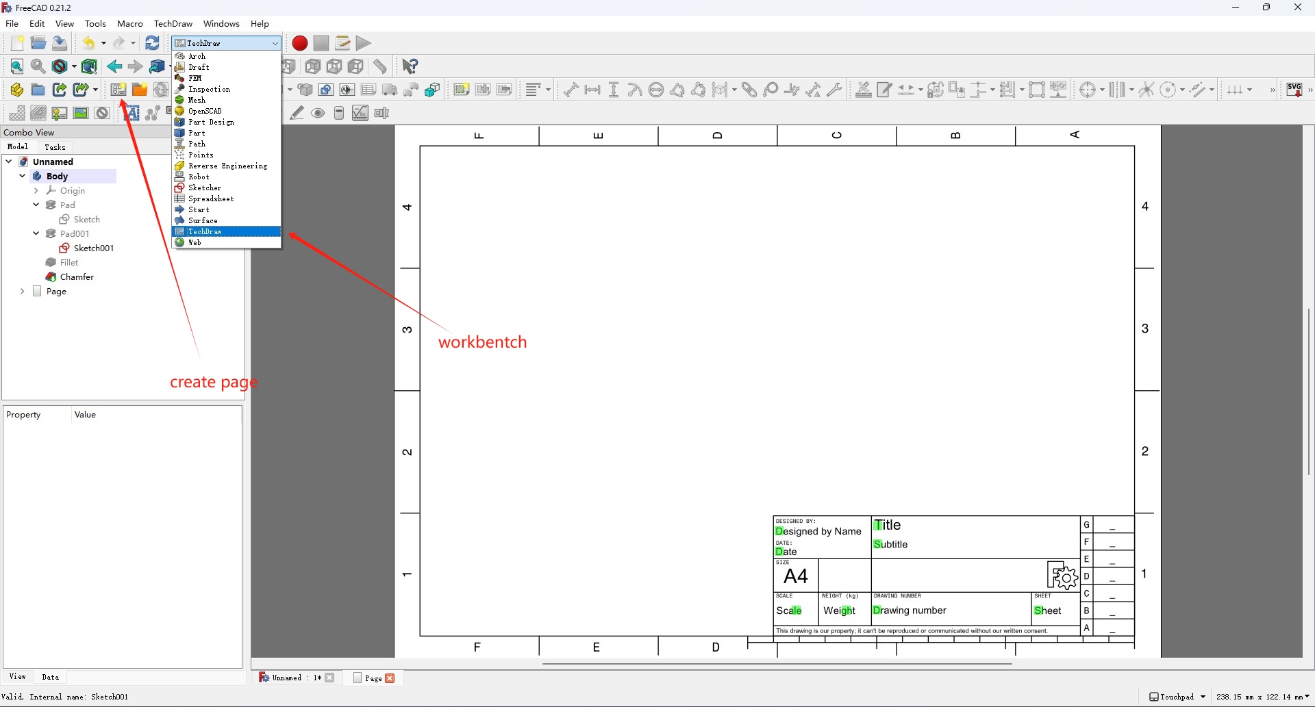
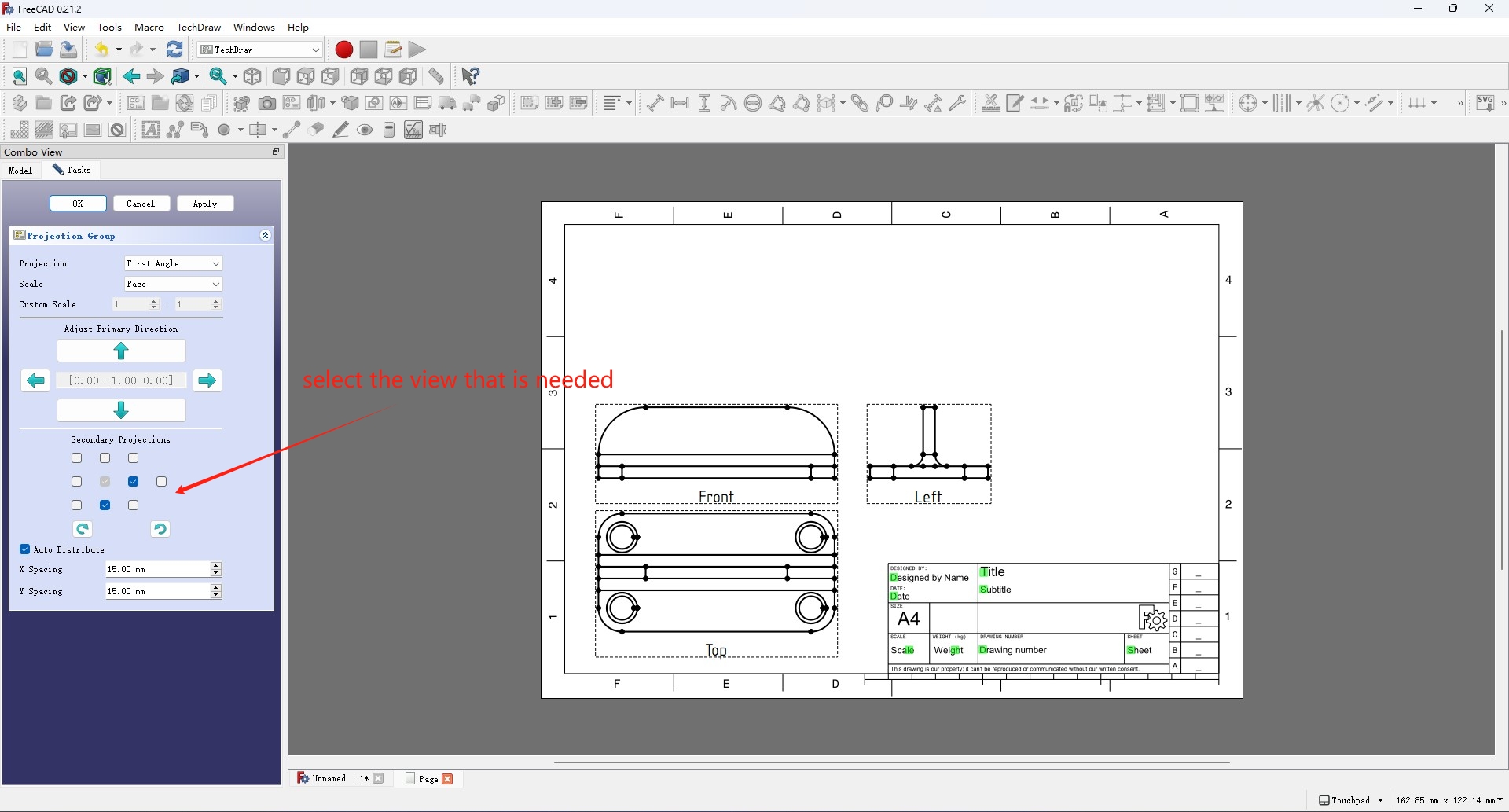
Then select the model from the Model tab on the left and change the view port into one of the orthographic view. Click the Insert Projection Group tool and a projection view is added to the page. Use the Secondary Projections checkboxs to add more views.
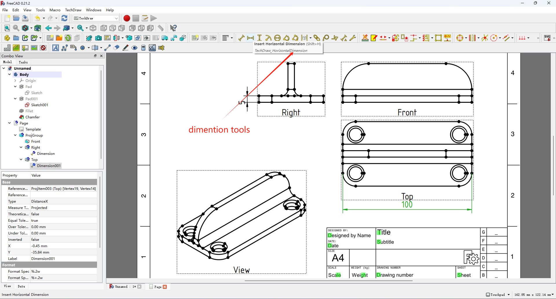
Then use the Insert dimentions tools to add dimentions to the drawing, as well as change the editible fields on the drawing.
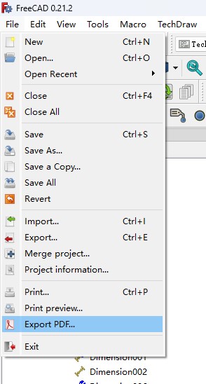
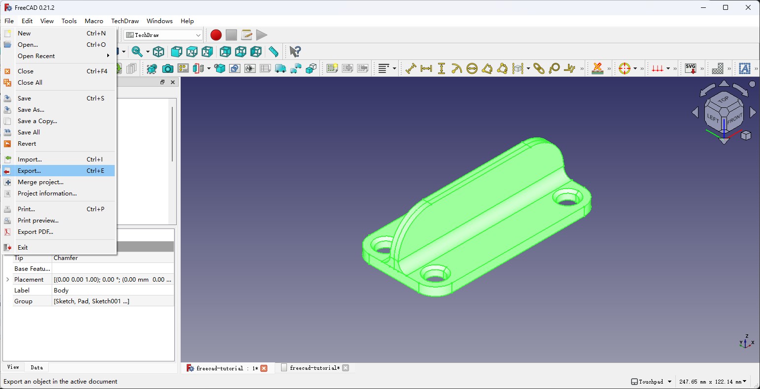
Then I can use the Export PDF function in the file menu to export the drawing to PDF file, as well as export the 3D model with the Export menu.
The technical drawing and the I made can be found at the bottom of the page via the links.
Possible Final Project
After that I went on modeling the the possible final project, the project ideation can be viewed here.
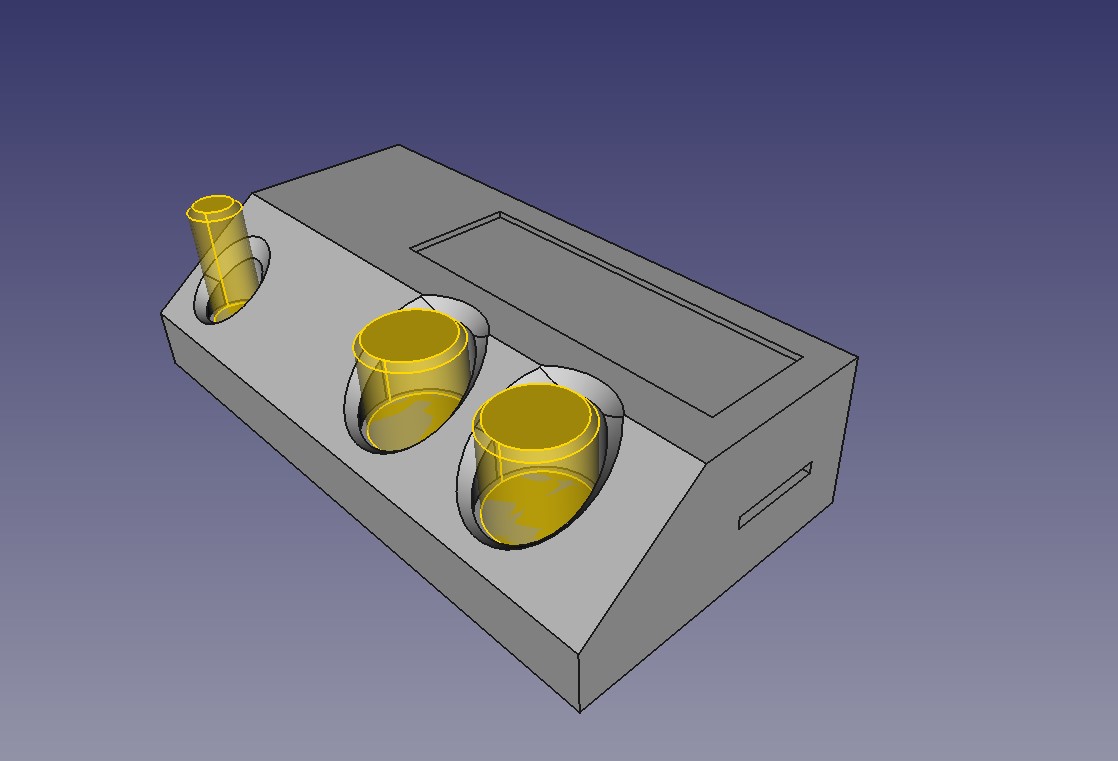
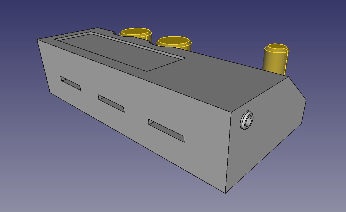
The FreeCAD project file is at the Project Files section.
Inkscape
For week03's vinyl cut assignment, I wanted to cut the logo of the Ecology and Cultures Innovation Lab which I'm a member of, to make some stickers for fellow lab members. But the logo file I got, as shown below, consists of several separate pieces, which are not very suitable for making stickers.

So I used Inkscape to make it a single piece.
The First Sticker

For the first one, I just added a circle outside of the whole shape and made the gourd shape logo the negative shape. The inner lines and the outer circle are now connected and form a single piece together.
The Second Sticker
For the second sticker, I wanted to make the outline smaller and be the same gourd shape as the logo itself. But I don't have the outline of the gourd shape in the SVG file, so I have to recreate it from the pieces myself somehow.
-
First, select all the paths and use the
Node Toolto select and delete all the nodes except the ones that form the outline.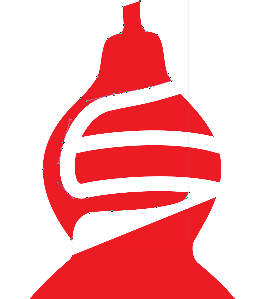
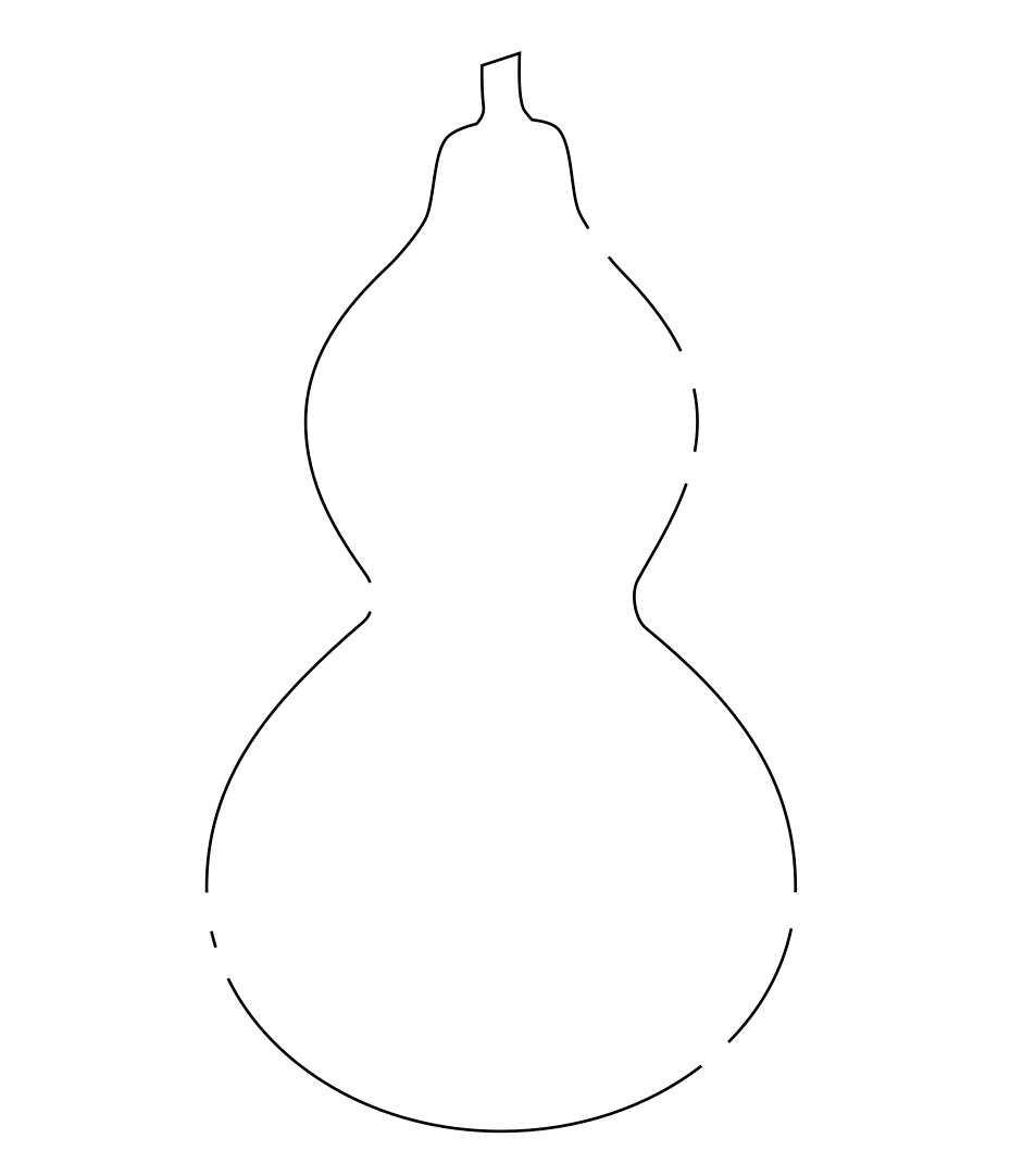
-
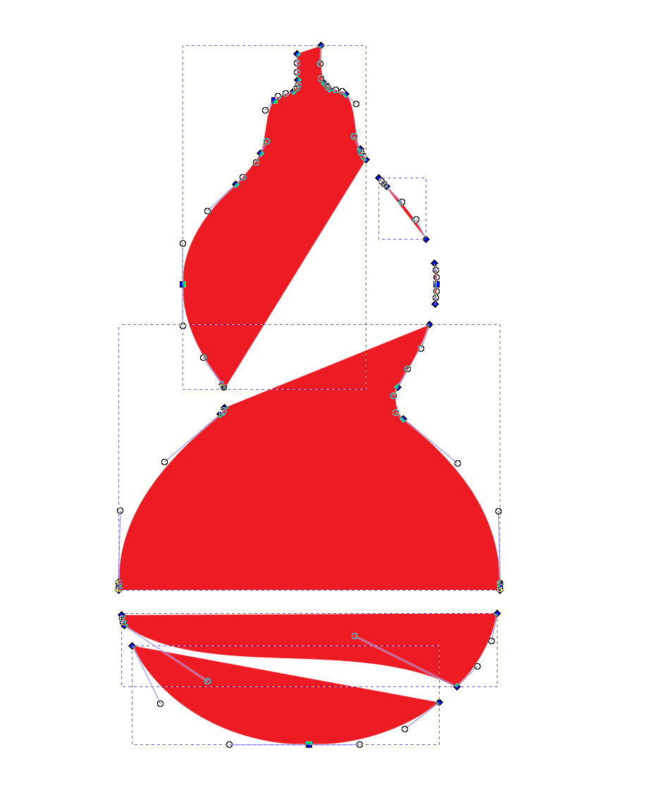
Then I first turned off the fill and applied stroke to the paths to see it more clearly and used the
Break path form selected nodestool in the toolbar to break and delete the unwanted lines left in the path.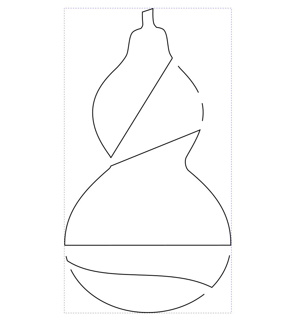
-
Then select the nodes between the two paths that are going to be joined and use the
Connect selected nodes with the new linetool and turn the joined nodes to auto smooth nodes or adjust the control handles for the nodes to make joined the path smooth.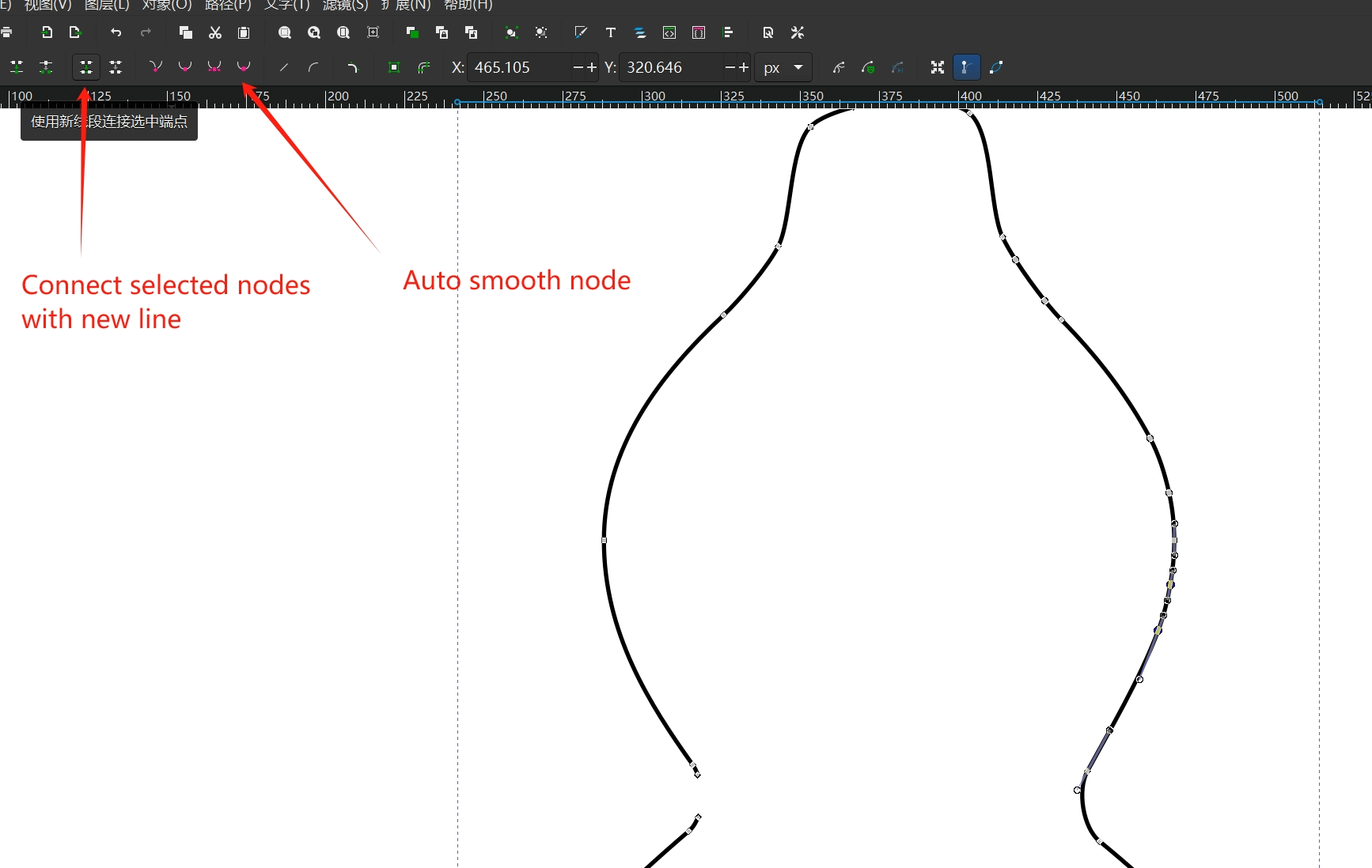
-
Now I have the outline of the logo that's like this.

-
Then I used the
Offset outertool in thePathmenu to make the outline a little bigger and applied an outline to it. Then align the original logo in the middle, now I get a shape that is connected by the outline in one piece.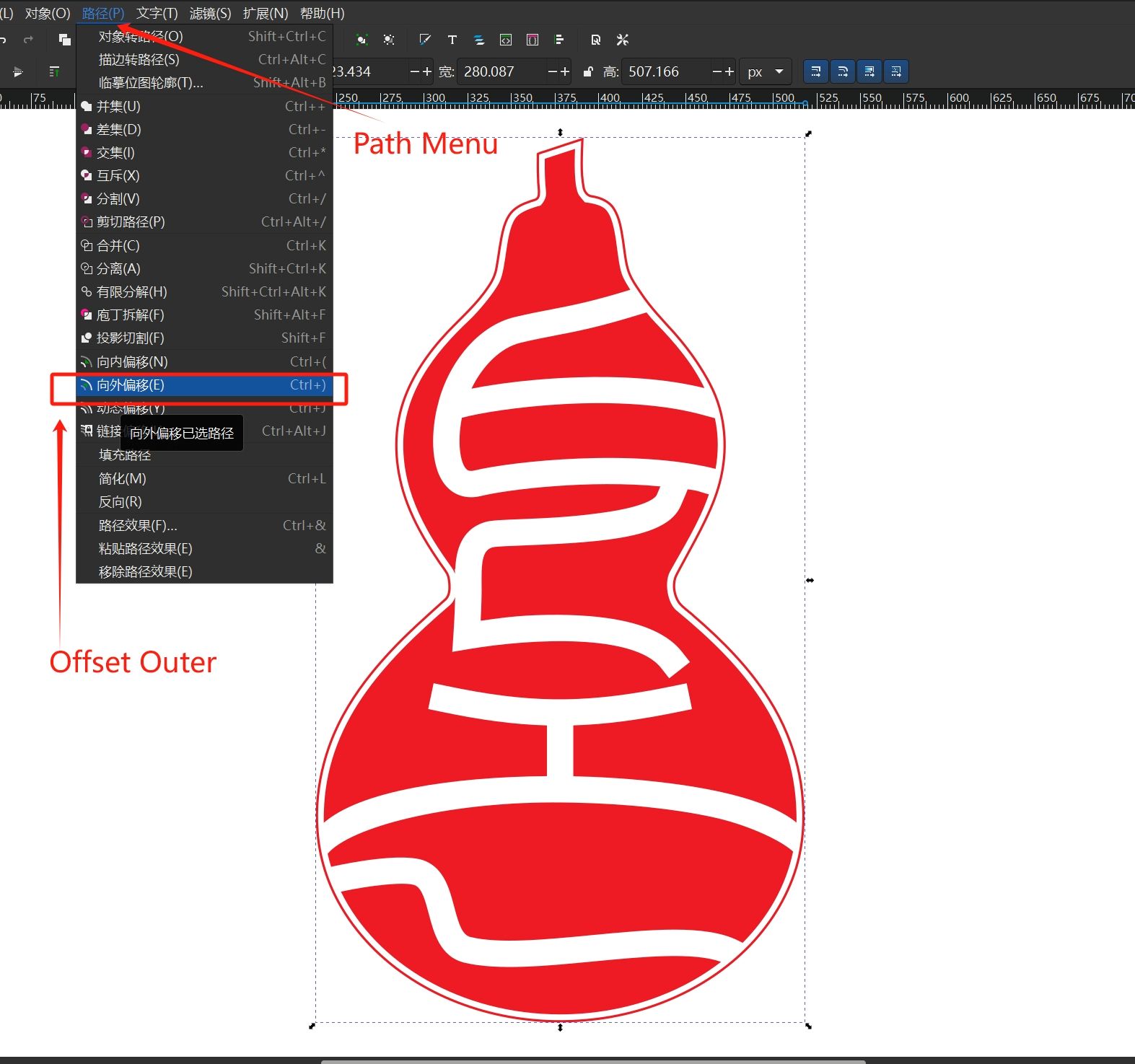

Project files
-
FreeCAD modeling exercice:
- Technical drawing: freecad-tutorial.pdf
- STL model: freecad-tutorial-Body.stl
-
Possible final project:
- FreeCAD project file: synth-model.FCStd
-
SVG stickers: