3.Computer-Controlled Cutting
This week we explore the process to do computer aided 2D cutting.
Assignment
-
Group assignmnet:
- Characterize your lasercutter's focus, power, speed, rate, kerf, joint clearance and types.
- Document your work to the group work page and reflect on your individual page what you learned.
-
Individual assignments
- Design, lasercut, and document a parametric construction kit, accounting for the lasercutter kerf, which can be assembled in multiple ways.
- Cut something on the vinyl cutter.
Group assignment
I've used the lasercutter before and never taken care of the cutting parameters. I just used the default parameters provided in the software. It's only after we did the tests for the lasercutter that I knew that the power can be turned down so much and it produces much finer finishes on the edges.
Link to this week's group assignment page.
Parametric construction kit: Wang Tile Map Tiler
Wang Tiles
Wang tiles is a concept originates from the question - Given a set of square tiles with a color on each tiles, arrange them side by side and with matching colors, whether they can fill the whole plane or not. It turns out that there exists the sets of tiles that can tile the plane aperiodically, and such concept can be used to generate non-repetitive patterns with a predefined sets of tiles, which is very useful in many applications.
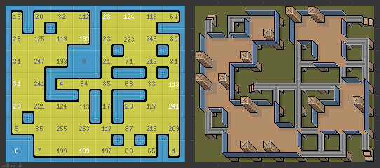
Below is a tile set that is proven to be the smallest set that can tile the whole plane, which consists of 11 tiles and 4 colors.

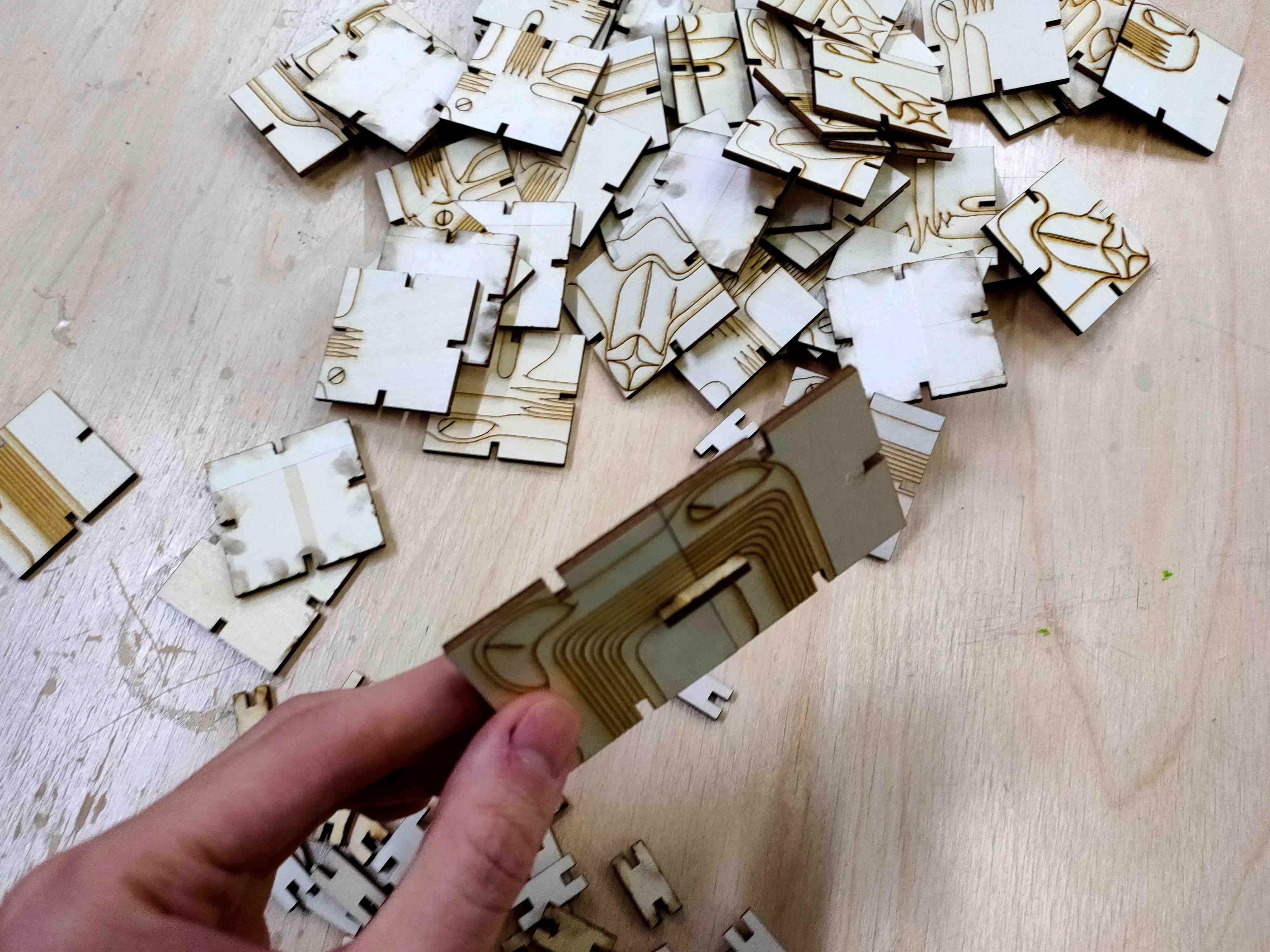
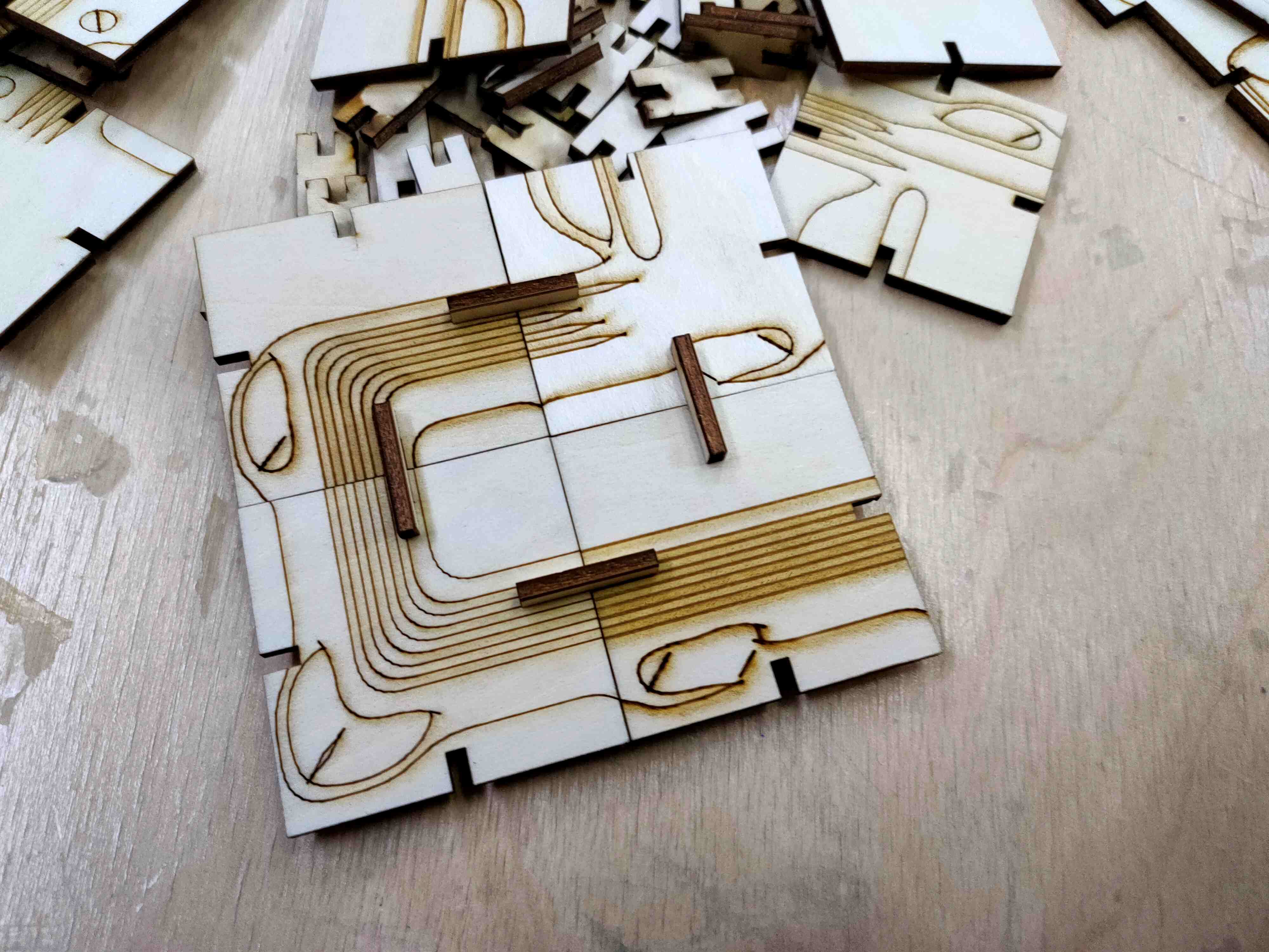
I want to explore with this concept, so I decided to cut a set of tiles that can be connected on the edges with joints in different ways, together they form a seamless pattern, which utilizes the property of Wang tiles.
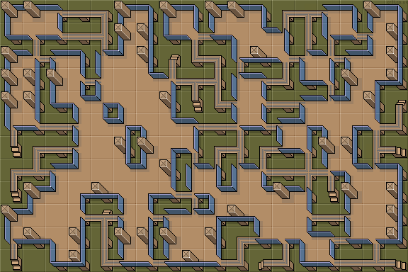
Below is a set of tiles I found on opengameart.org, the tiles can be connected on the sides seamlessly in different ways to form a non repeative pattern.
Parametric 2D design in FreeCAD
To make the tiled map based on Wang Tile, I need to make serveral square-shaped tiles and join them on the edges. I decided to go with basic press-fit joints between the tiles but make them relatively small to show the patterns on each tiles.
The image pattern of the tile set is often defined in the form of an image containing an array of every pattern, just like the one I picked. So I need to arrange the cutting path into the same array as the image. So I just need to parametize the row and column count of the tile set image, the size of the tiles and the size of the joint, then overlay the tile set image over the cutting path to make the tiles.
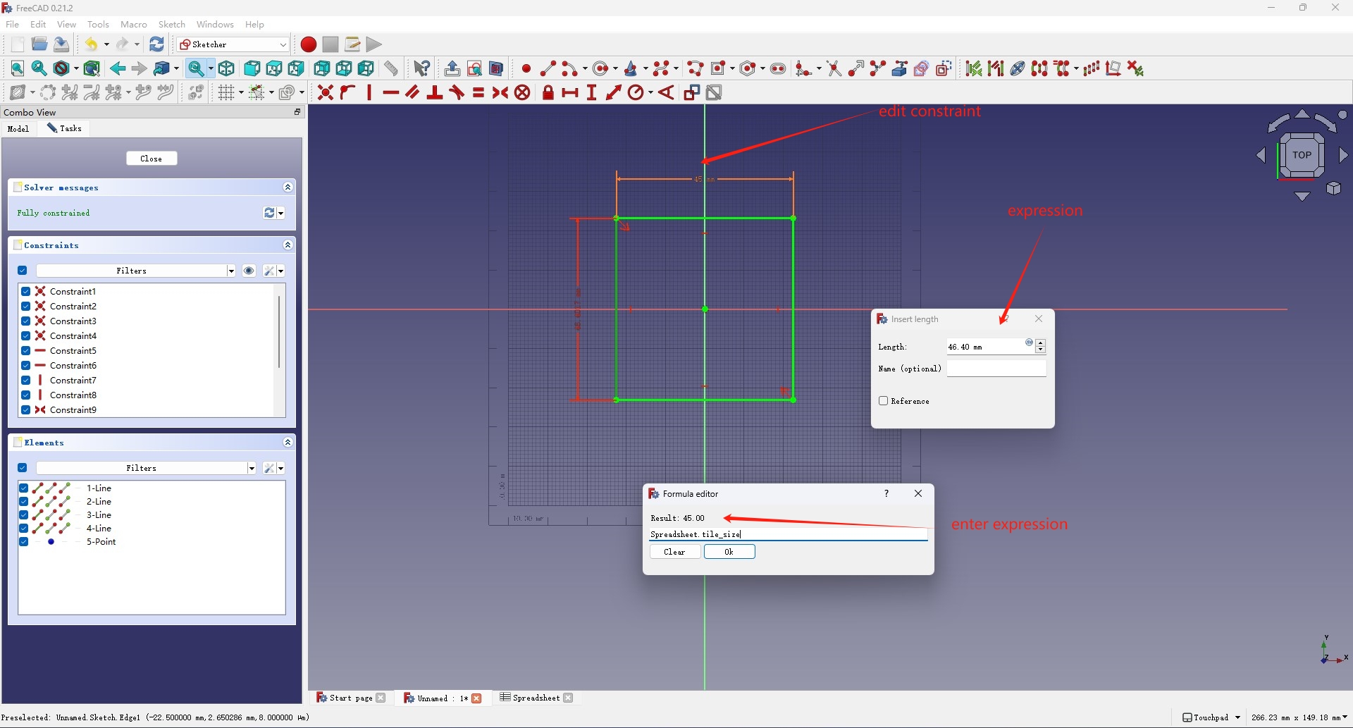
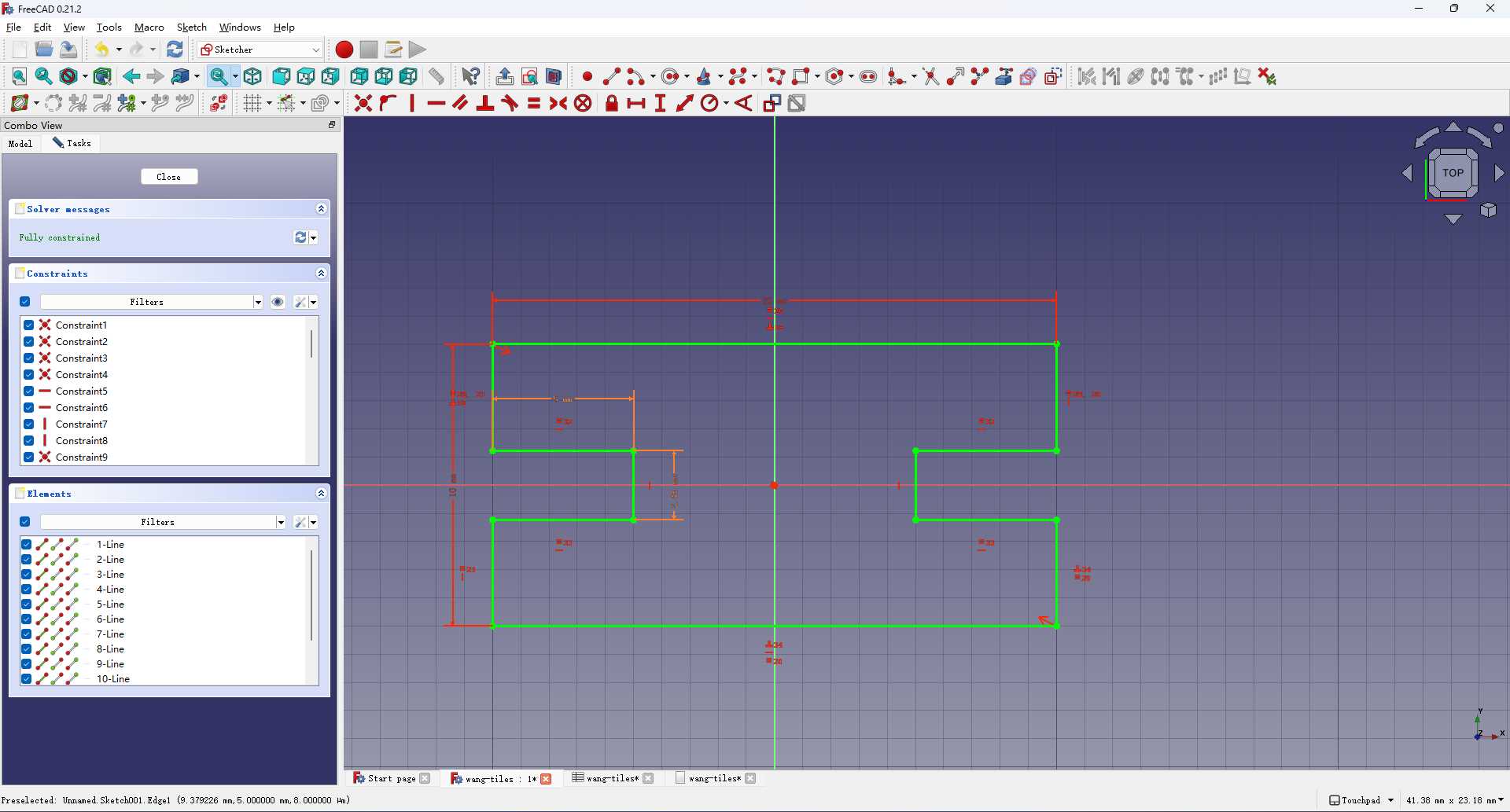
So I start off creating a 2D sketch in the Sketcher workbench. First create a square in the XY-plane and set a length constraint on the side to control its size.
Then open up the Spreadsheet workbench, click Create Spreadsheet and select
the spread sheet in the Model Tab. Select one cell in the sheet and edit its
alias field on the top-right corner, the alias will then be used to link the
value of the cell to other part of the drawing. I first set the alias
"tile_v_count", "thie_h_count" and "tile_size" for 3 cells and set their
values.

Now go back to the sketch and double click the constraint, select the
Expression button to enter the constraint value as an expression, set it to
"Spreadsheet.tile_size", and the constraint will use the corresponding value
aliased in the spread sheet. Now the size of the square is controlled by the
value in the spreadsheet.
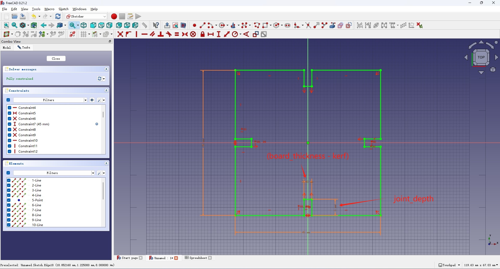
Then I start sketching the joints on each size of the square and added constaint
for the lenght and the width of the joint. I added the "kerf",
"board_thickness" and "joint_depth" to the spreadsheet and the value of the
constraints are computed from those values. Specifically, the width of the joint
is set to "Spreadsheet.board_thickness - Spreadsheet.kerf".
Then go to the Draft workbench and select the Array tool, then go to the
Property Tab and adjust the Interval X, Interval Y and Number X, Number
Y properties, set their values to the expression in the spreadsheet
acclordingly. The X and Y axis intervals are set to "Spreadsheet.tile_size"
and the X, Y number are set to the "tile_h_count" and "tile_v_count". Now
the drawing can be adjusted by the parameters in the spreadsheet.
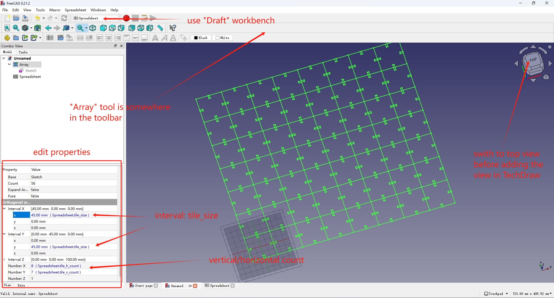
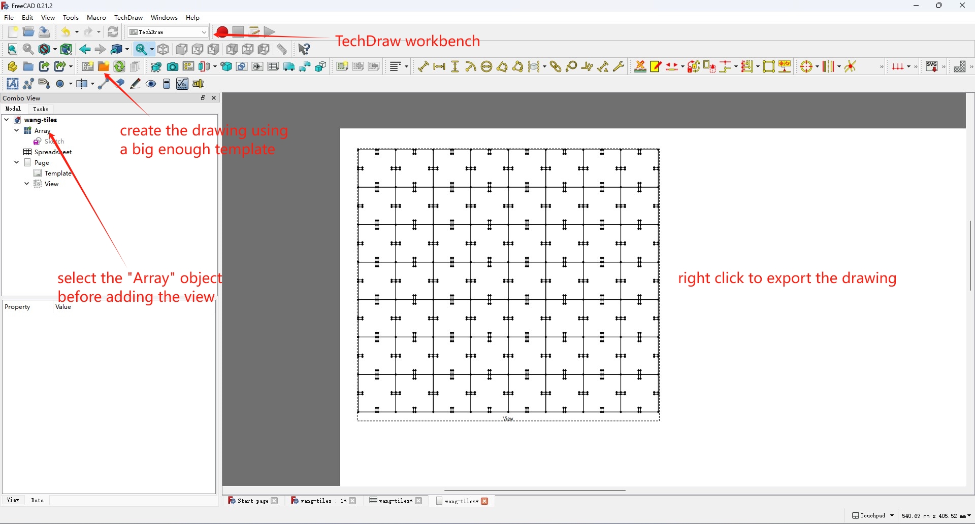
Then open the TechDraw workbench and create a new drawing, select the array in object on the left in the Model tab and click the 3D gimbal to switch the view box to the top view. Then click Insert View to add the view to the drawing and right click to export it as DXf file.
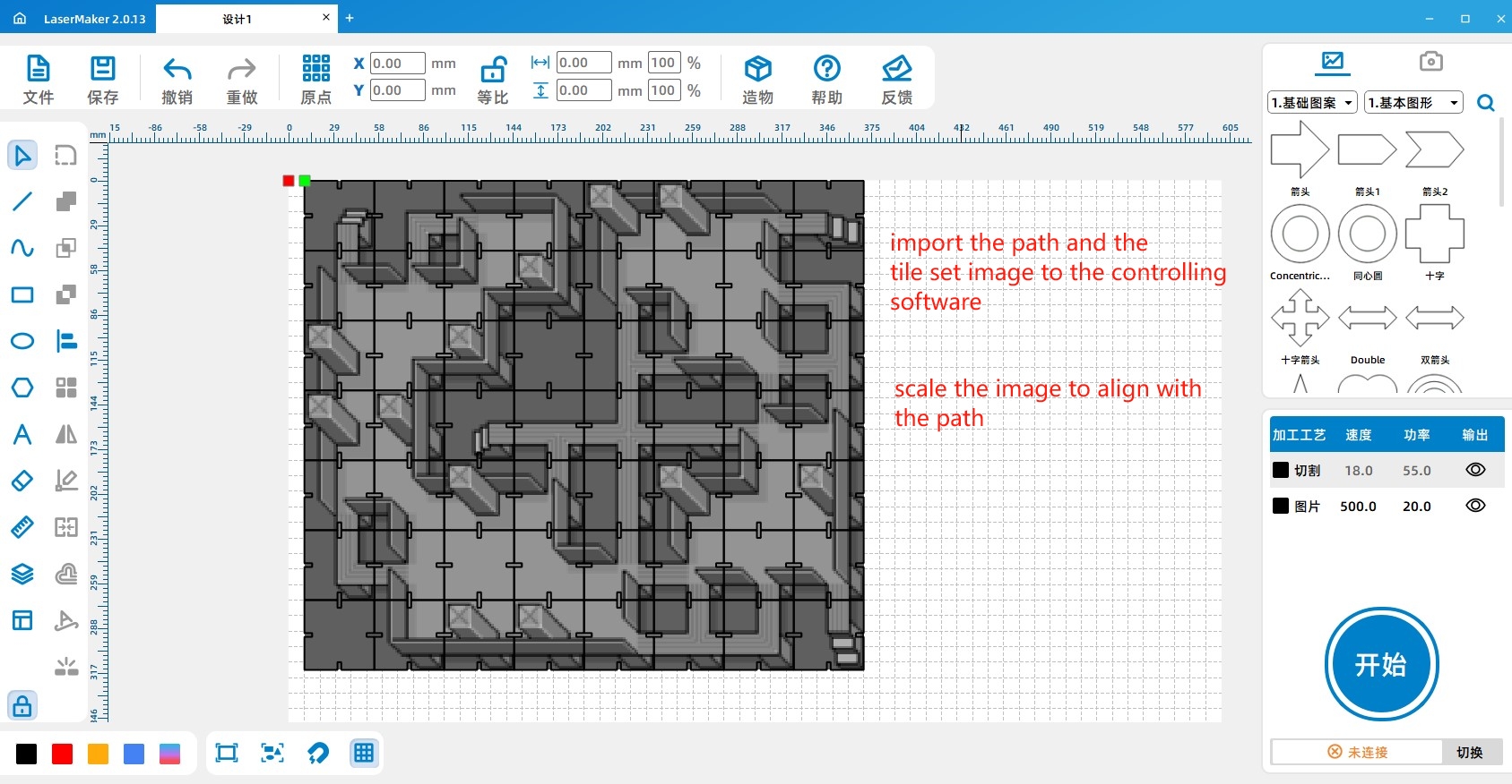
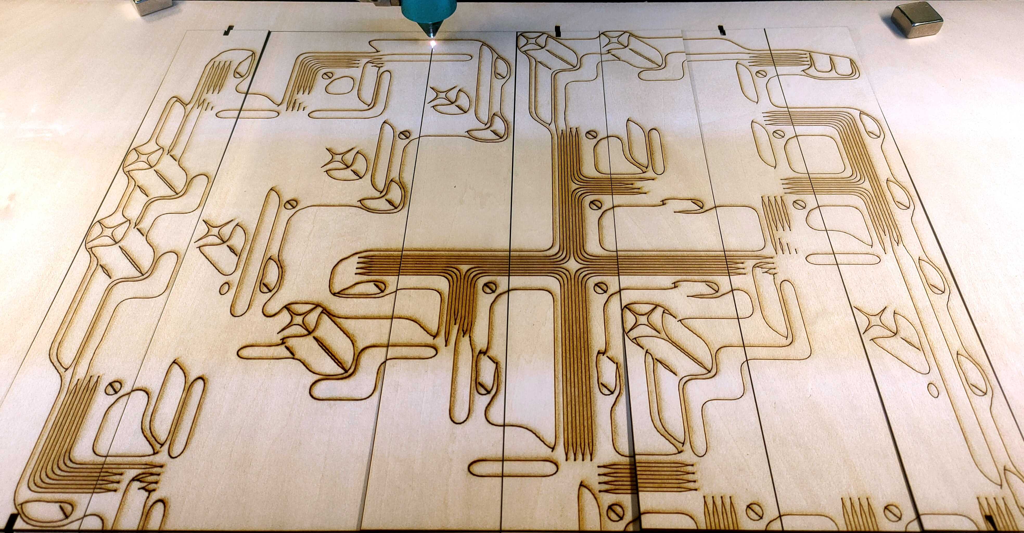
Then I import the generated DXF file into the Lasercutter controller program -
Lasermaker and import the tileset image, scale it can put it over the path of
the tiles to make the engraving of the pattern.
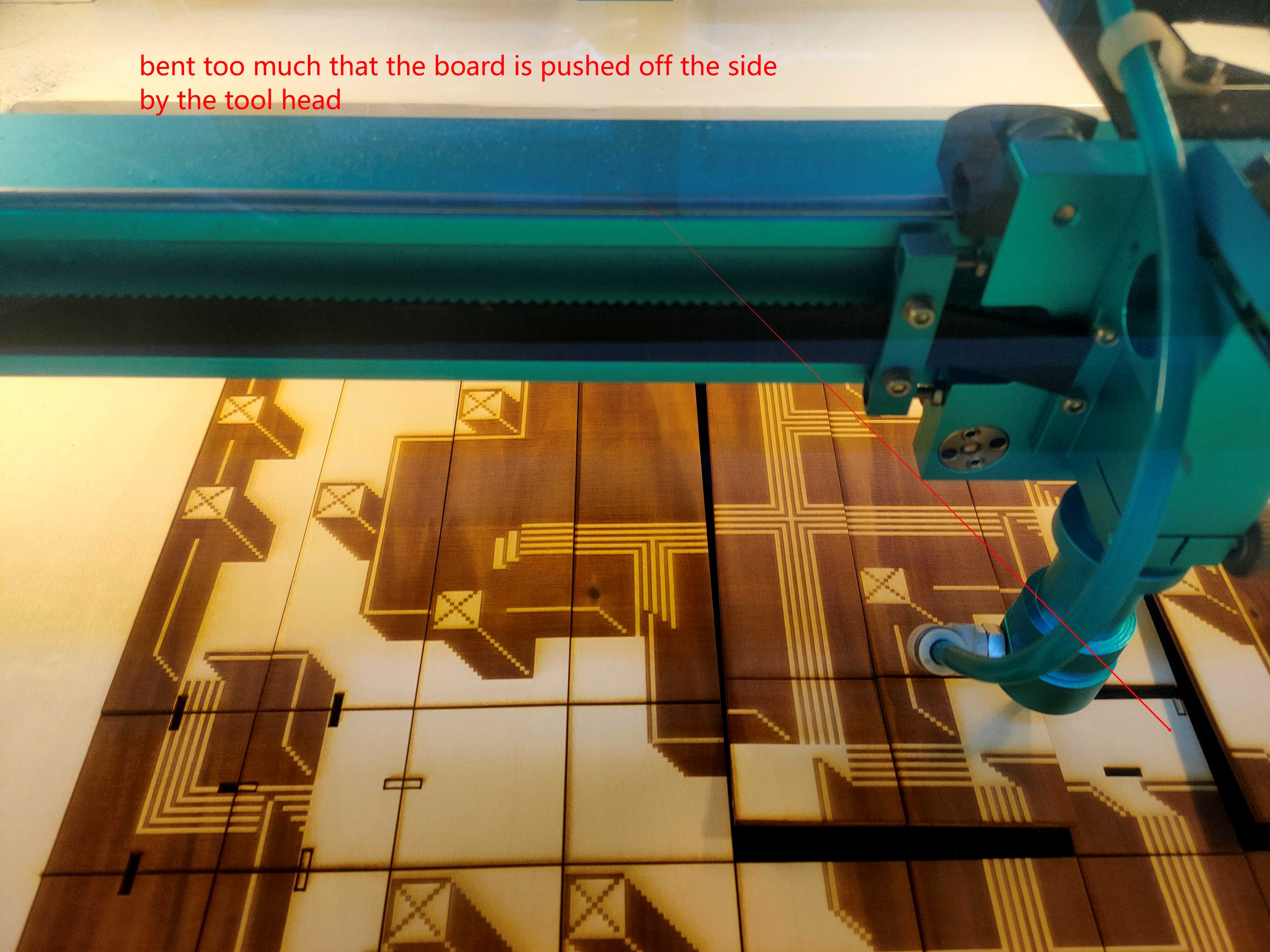
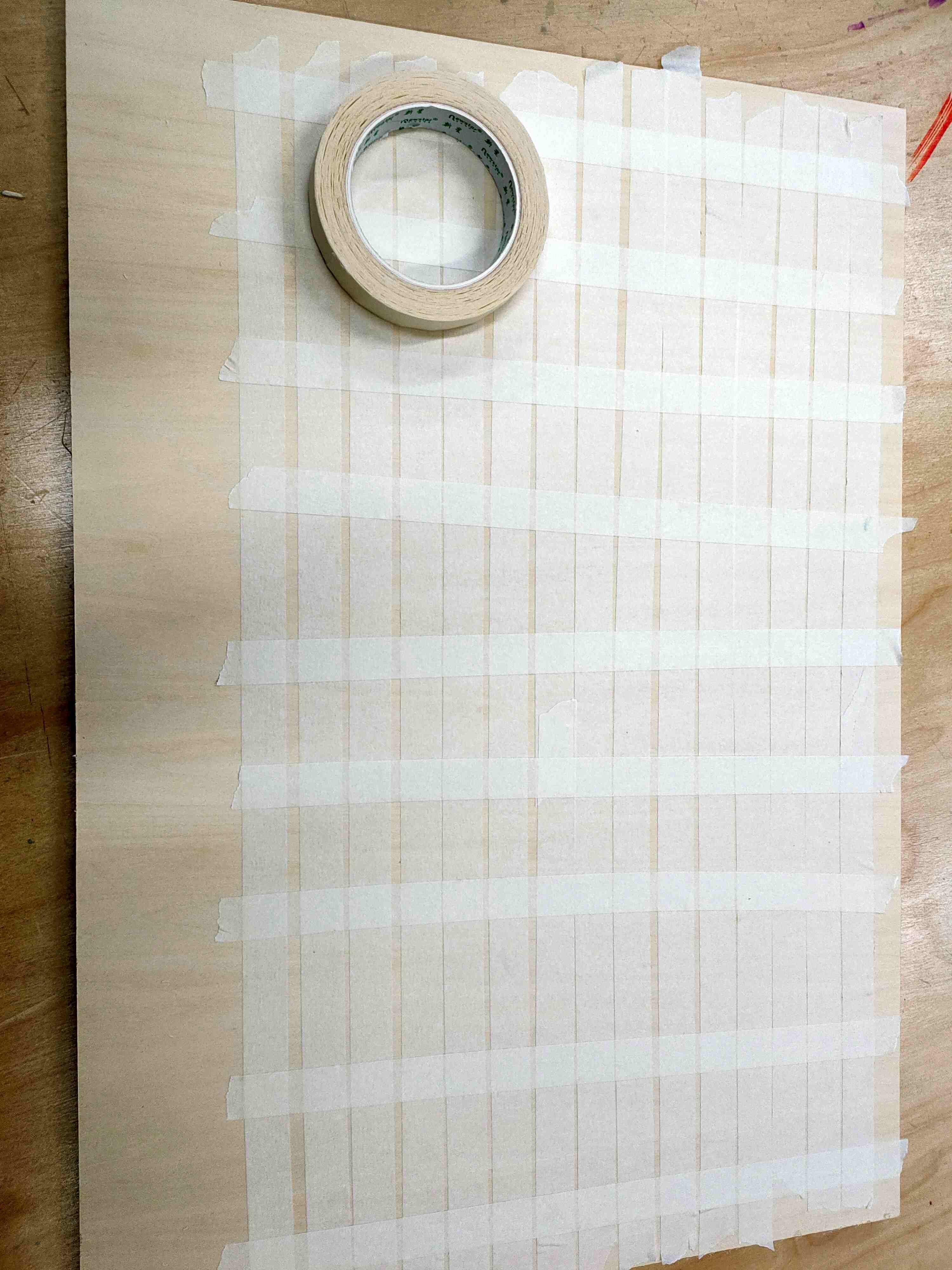
Adjust the speed and power, then just start the cutting. On the first time, the plywood material bends heaveliy because of the engraving and is pushed to the side. So I taped the back size of the board and used the line tracing functionality of the software to change the engraving to line drawing, and the tiles were cut cleanly this time.
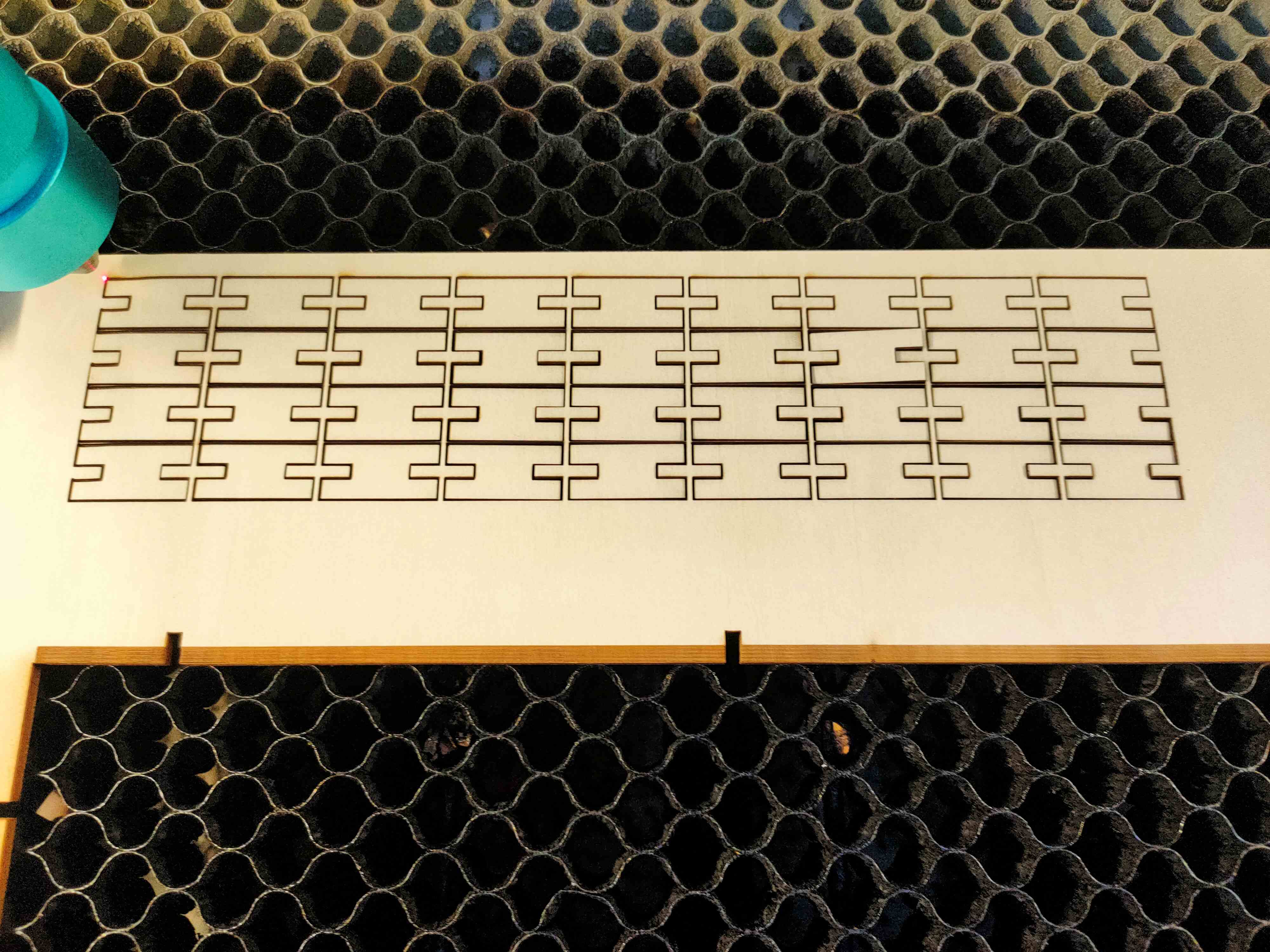
Then make the joints using the same approch, and cut them. The connections are very good.
Vinyl Cutting the Logo of Ecology Lab

I want to cut a sticker of Ecology and Cultures Innovation Lab that I'm a member of.
The process of how I created the SVG files for cutting is documented in week02
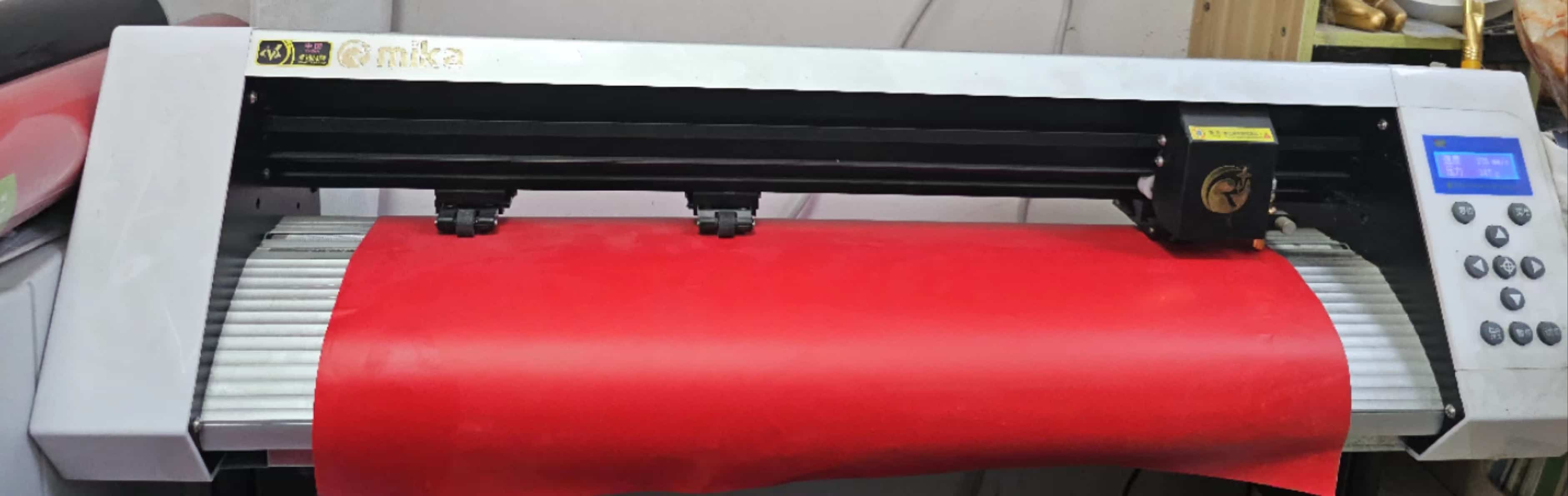
The machine we used for cutting is called MIKA. To do the cut, first insert the PVC material from below and open the file in CorelDRAW, adjust the position of the file and the cutting parameters.
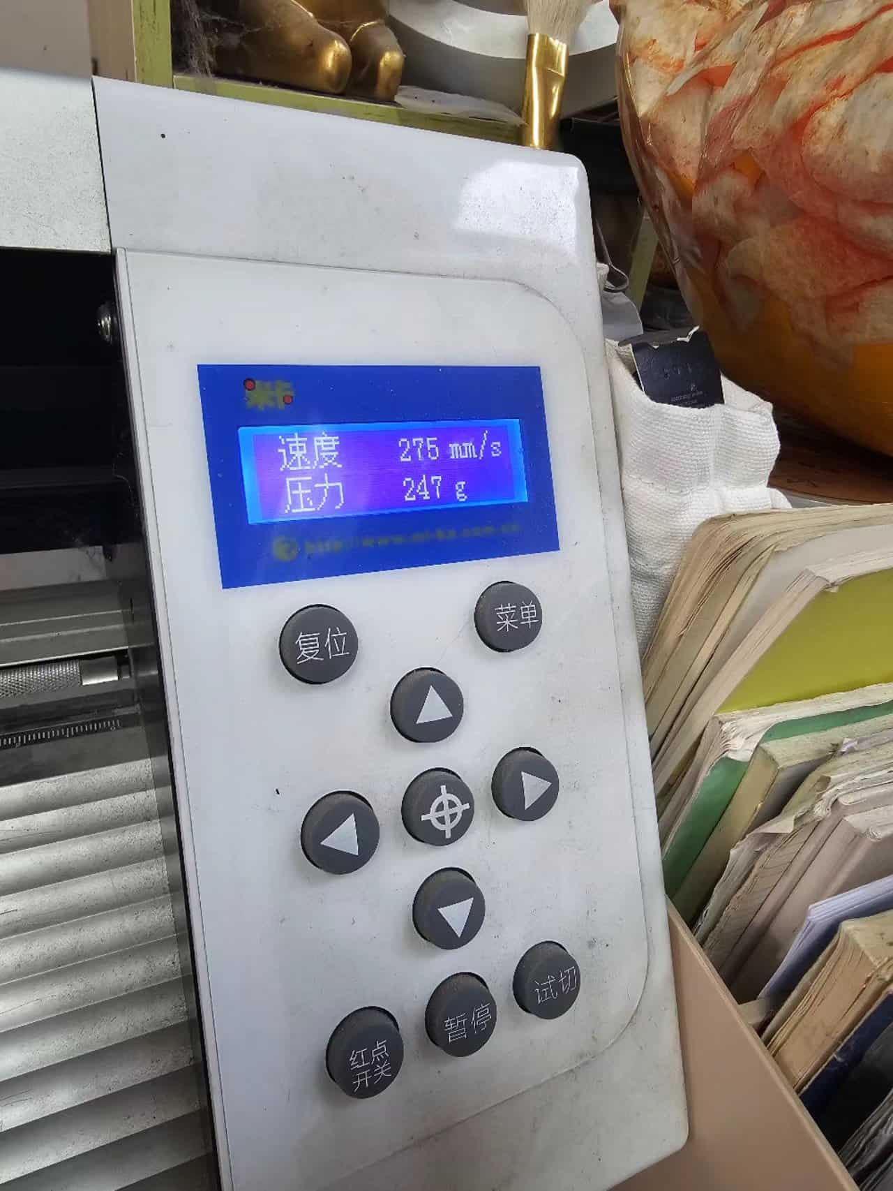
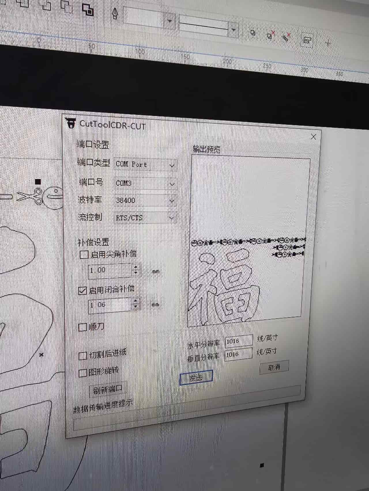
The parameters we were using is "Speed 274mm/s, Pressure: 247g".
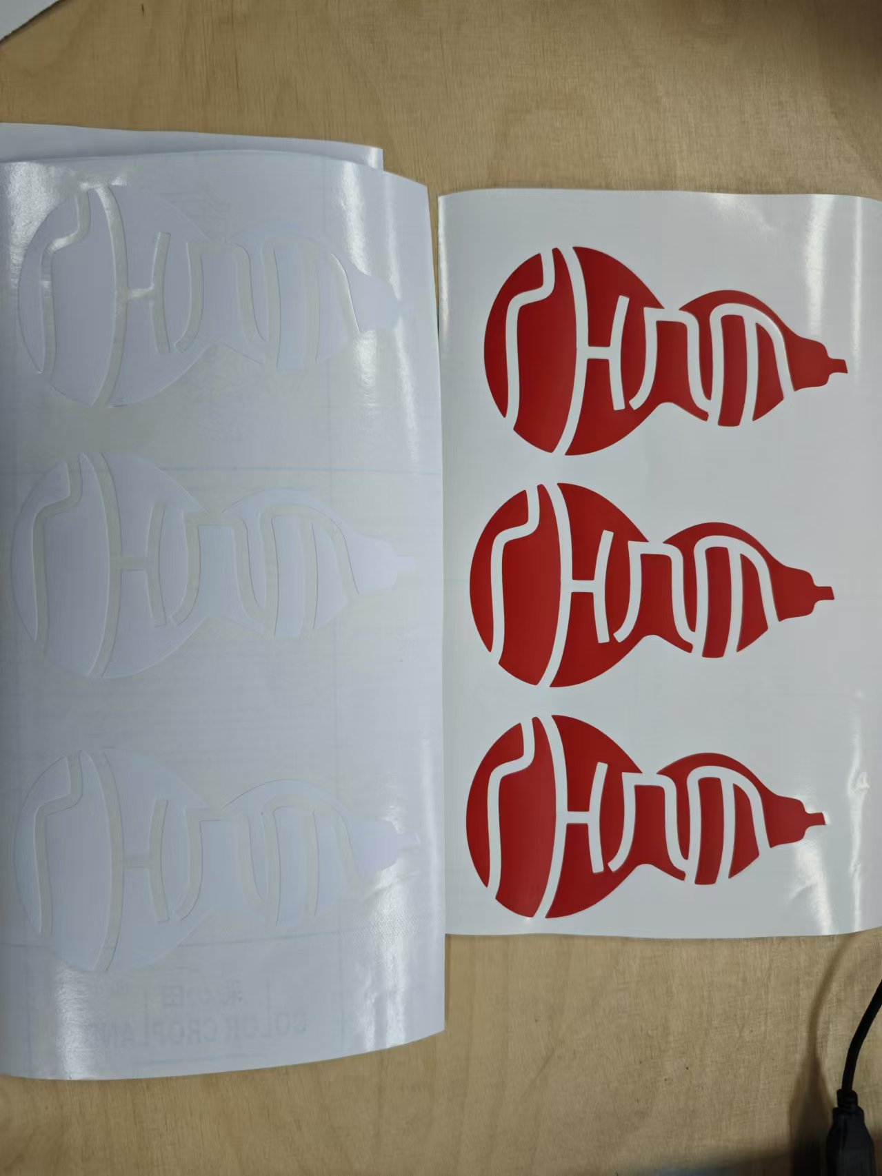
The final cutted pieces were in two colors.
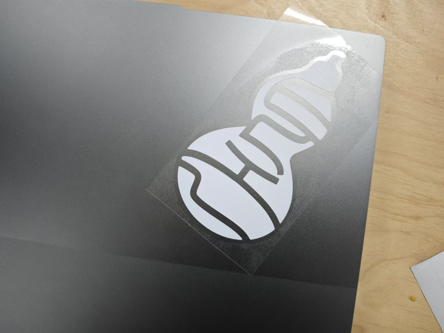
Although I did some modification to the logo vector graphics to make it connected instead of sperated in serveral pieces, I found that I can use the transport paper to trasport them together. So I decided to cut them in pieces.
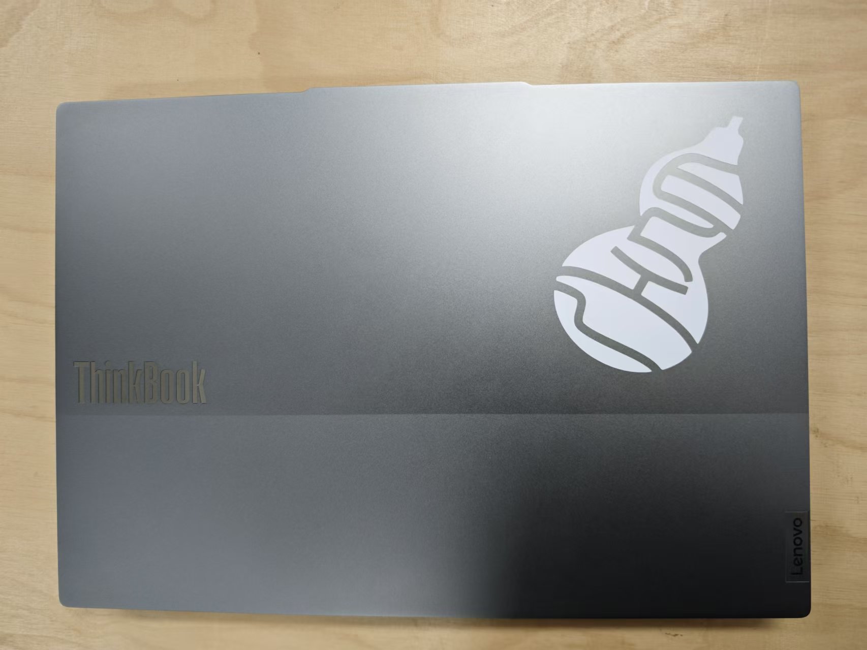
I used the transport paper to keep them in place and stuck them on to my laptop.
![]()
![]()
![]()
Now I have a lovely "Hulu" on my laptop.
Project files
-
Wang Tile press fit kit:
-
FreeCAD project file: wang-tiles.FCStd
-
Tiles DXF file: tiles.dxf
-
Tile image:
-
-
Vinyl cut:
-
Logo SVG:

-