11. Input Devices
Assignment
-
Group assignment:
- Probe an input device(s)'s analog levels and digital signals
- Document your work on the group work page and reflect on your individual page what you learned
-
Individual assignment:
- Measure something: add a sensor to a microcontroller board that you have designed and read it.
Group assignment
This week we did some tests on our daily used input devices, and checked their specs that we have not looked carefully before.
Link to this week's group assignment
Capacitive touch sensing on PCB
The board I made on week8 has 10 copper pads on it and has capacitive sensing capability. I've did some testing to make sure that it's working, and I'm doing some more testing learn more about the sensors.
Seeing the Web Serial example presented by Neil, I decided to make one myself, and I also wanted to have some more visualization to inspect the values of my capacitive sensors better.
So I made this web page to receive the values from my board and using the Web Canvas API draw the values as histogram to view them change in real time. You can also connect your board to send serial data to the web page to display, but the data format is not adjustable, it only can handle data that's 12 numbers each line, with each of them seperated by a space in between. The first 10 are the values of the capacive sensors reading and the last 2 are the index of the last touched pad and the time taken to process all the input once.
Below is the Arduino program for sending the data with the serial port, some more details about the PCB and library in use is described in week08 and week09.
#include <CapacitiveSensor.h>

CapacitiveSensor pads[] = {
  { 2, 3 }, { 2, 4 }, { 2, 5 }, { 2, 6 },
  { 2, 7 }, { 2, 8 }, { 2, 9 }, { 2, 10 },
  { 2, 11 }, { 2, 12 },
};
#define array_len(a) (sizeof(a) / sizeof *(a))

void setup() {
  Serial.begin(9600);
  Serial.println();
  pinMode(13, OUTPUT);
}

unsigned long last_touch_time[array_len(pads)] = {};

void loop() {
  unsigned long start = millis();

  int last_touched = -1;
  for (int i = 0; i < array_len(pads); ++i) {
    long val = pads[i].capacitiveSensor(30);
    bool current = val > 200;
    if (current) {
      if (last_touch_time[i] == 0) {
        last_touch_time[i] = millis();
      }
      if (last_touched < 0 || last_touch_time[last_touched] < last_touch_time[i]) {
        last_touched = i;
      }
    } else {
      last_touch_time[i] = 0;
    }
    Serial.print(val);
    Serial.print(" ");
  }

  // print each value of the pads the print the last touched pad
  // and the processing time, separated by space

  unsigned long processing_time = millis() - start;
  Serial.print(last_touched);
  Serial.print(" ");
  Serial.print(processing_time);
  Serial.print("\n");
}
Here's a video of the web page and the board working together.
A detailed explanation of how I the visiualization is done is on week14's assignment page
Not working with acrylic on top
For my final project, I'd like to try to cover my capacitive pad with a piece of acryic to make it look nicer and more durable. But I grabed one piece from the lab and tried it quickly, and it didn't seem to detect my touch with the piece in between, I might try more to see if I can make it work.
GY-91 9-axis inertial measurement unit (IMU)
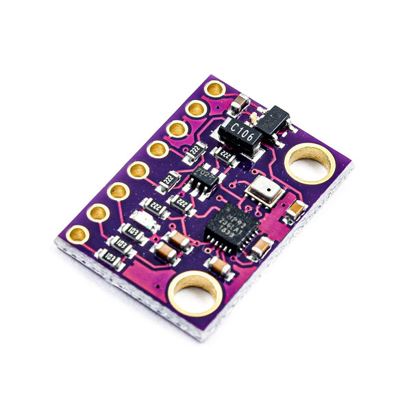
The GY-91 is a sensor module that combines two sensors on a same board. It has an InvenSense MPU9250, which is a tri-axial accelerometer, gyroscope and magnetometer, has 9 degress of freedom and can provide direction, acceleration and position information and motion tracking functionality. The other one is the Bosch BMP280, which is an barometric pressure and altitude sensor. Both of them use I2C interface to communicate, so they can be controlled with the same set of I2C pins on the module.
For this week's assignment, I just use the MPU9250 to try the motion tracking functionaliy. The MPU9250 library for Arduino can be used to control the MPU9250 sensor on the module. Below is the code used to read the 'Yaw, Pitch, Roll' Eular angles from the sensor and send the values with the serial moniter. Eular angles are three angles that can be used to repersent the orientation of an object in 3D space.
#include "MPU9250.h"

MPU9250 mpu;

void setup() {
  Serial.begin(9600);
  Wire.begin();
  delay(2000);
  if (!mpu.setup(0x68)) {  // change to your own address
    while (1) {
      Serial.println("MPU connection failed. Please check your connection with `connection_check` example.");
      delay(5000);
    }
  }
}

void loop() {
  if (mpu.update()) {
    // print raw, pitch, roll data every 25 milliseconds
    static uint32_t prev_ms = millis();
    if (millis() > prev_ms + 25) {
      print_roll_pitch_yaw();
      prev_ms = millis();
    }
  }
}

void print_roll_pitch_yaw() {
  Serial.print(mpu.getYaw(), 2);
  Serial.print(" ");
  Serial.print(mpu.getPitch(), 2);
  Serial.print(" ");
  Serial.print(mpu.getRoll(), 2);
  Serial.print("\n");
}
Just connect the sensor to the I2C pins and I'm able to receive motion data from it.
The program just prints the three angles on one line with space between them, below I can tell from the serial monitor that the values are changing when I move the sensor.
Visualizing the rotation using WebGL
I also made a web page using WebGL to draw a simple sphere and make it rotate accroding to the data sent by the board, this helps a lot with visualize the rotation data and I can easily tell how these values change when the sensor moves.
A detailed explanation of how I the visiualization is done is on week14's assignment page
Source files
-
Capacative touch sensing
- Arduino program: atmega328-capacitive-web-serial.ino
- web page: web-serial.html Download
-
WebGL visualization for MPU9250
- Arduino program: mpu9250-serial-webgl.ino
- web page: mpu9250-serial-webgl.html Download