8. Electronics Design
Assignment
-
Group assignment:
- Use the test equipment in your lab to observe the operation of a microcontroller circuit board (as a minimum, you should demonstrate the use of a multimeter and oscilloscope)
- Document your work on the group work page and reflect what you learned on your individual page
-
Individual assignment:
- Use an EDA tool to design a development board to interact and communicate with an embedded microcontroller
Group Assignment
This week we tried different testing equipment in our lab. I knew how to use the multimeter but have never really used a oscilloscpe before, and now I truely know how to use one. It's good to see the audio signal being output by the board, and it'll be very useful when building my final project.
Link to this week's group assignment
Capacitive Sensing with ATmega328p
As part of my final project, I think my synth will need an input device to be able to control the pitch of the final generated sound, so I decided to make a capacitive sensing boa rd that can use touching as input.
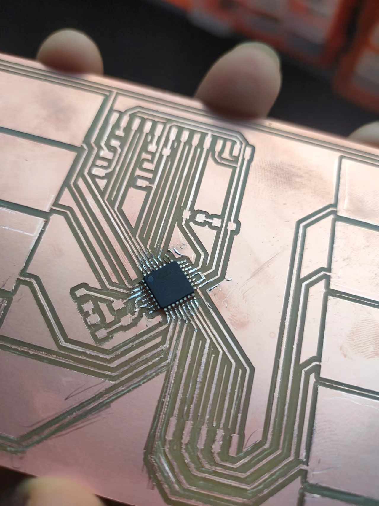
We have some ATmega328p in stock and since I have cut one board working with the DIP packaging, I decided to make one with the MLF package this time.
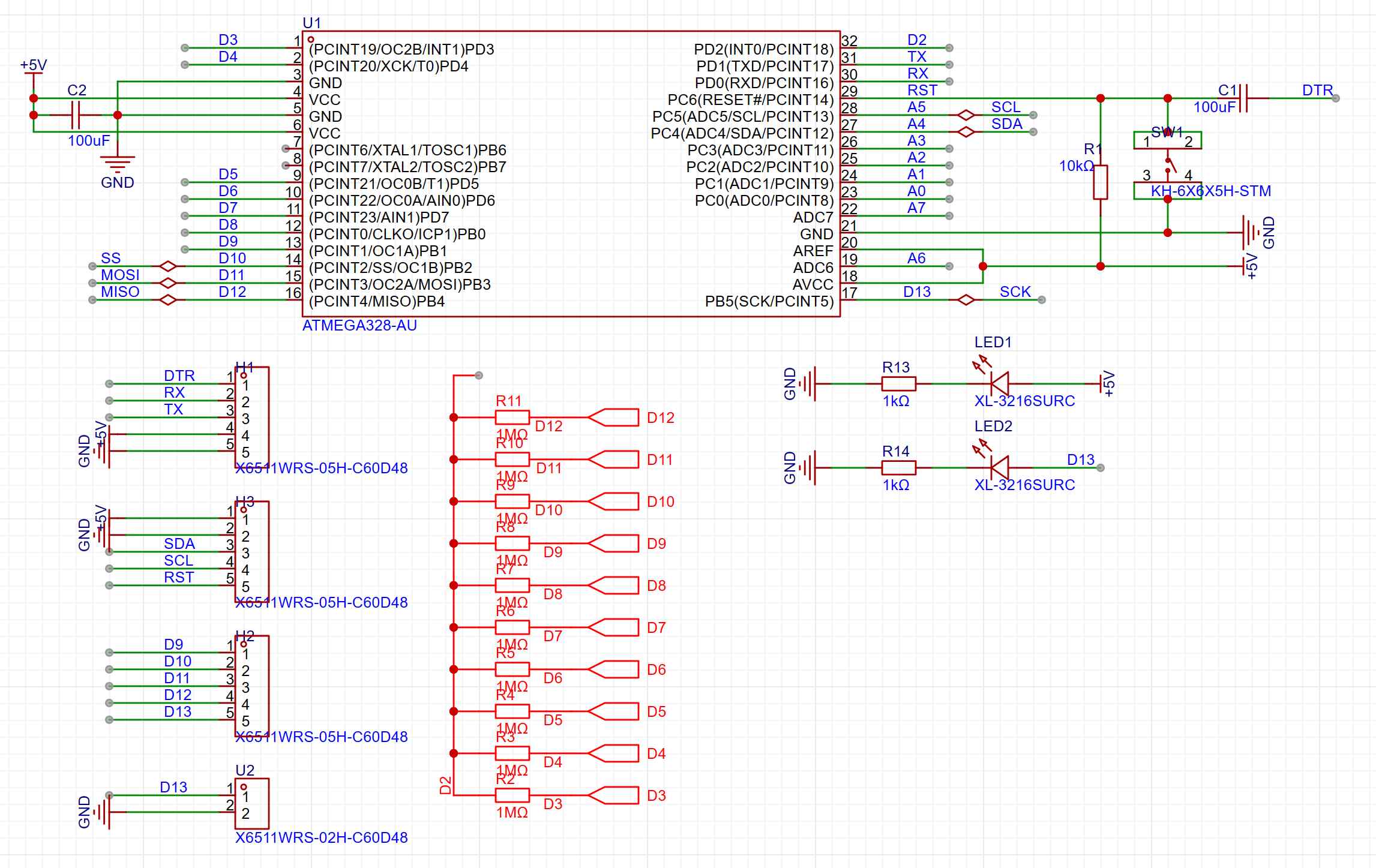
Schematic
For the schematic I have 10 copper pads connecting to the digital pins 3 to 12 and all of them are connected to pin 2 through a 1MOhm resister. This will be the capacitive sensors that will be used. I also exposed the UART pins on pin 0 and pin 1, A4 and A5 for I2C communication and the SPI interface on pin 11 to 13 and reset for burning the bootloader wit h the external programmer. I also put a reset button and a LED on pin 13.
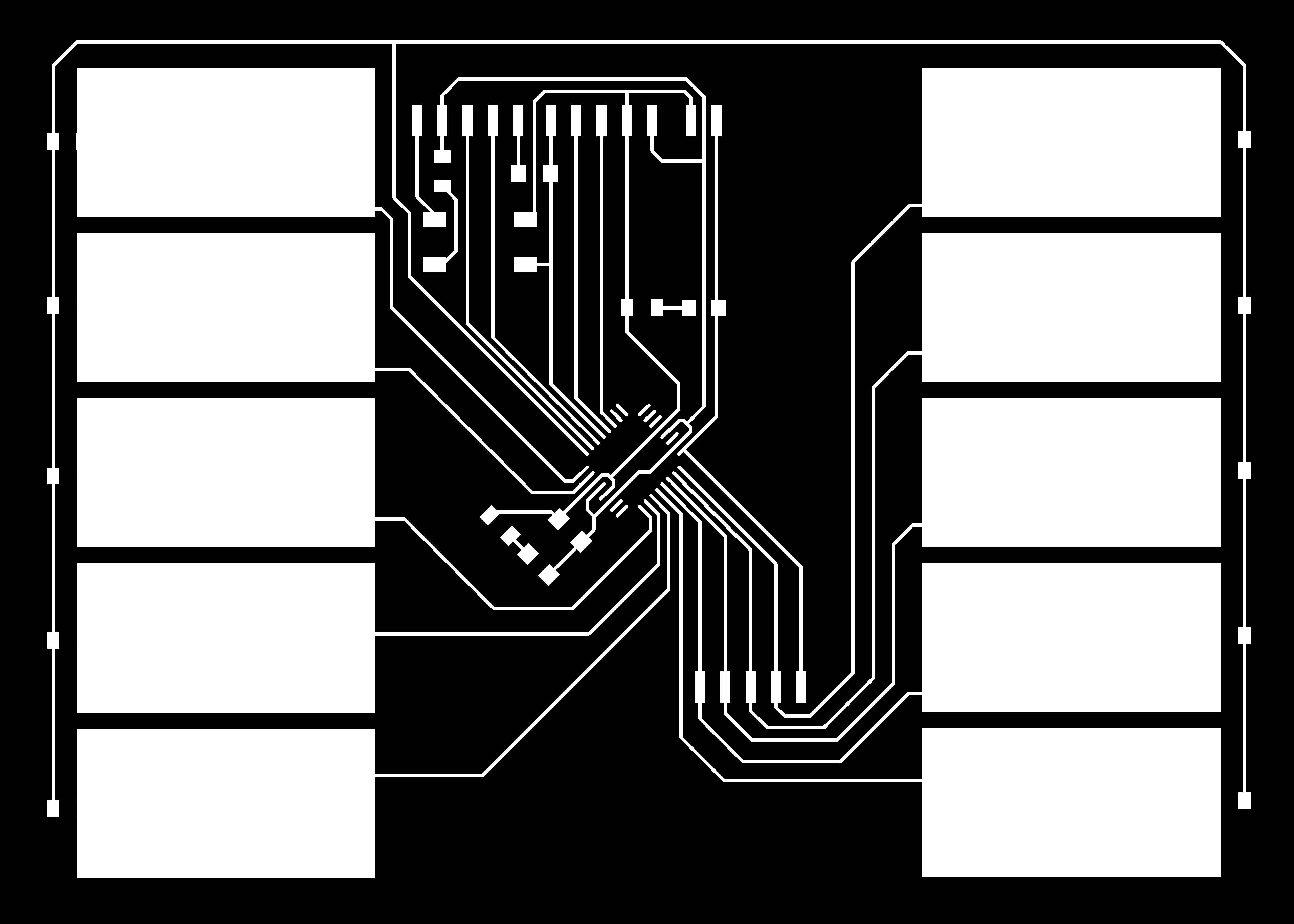
Board Layout
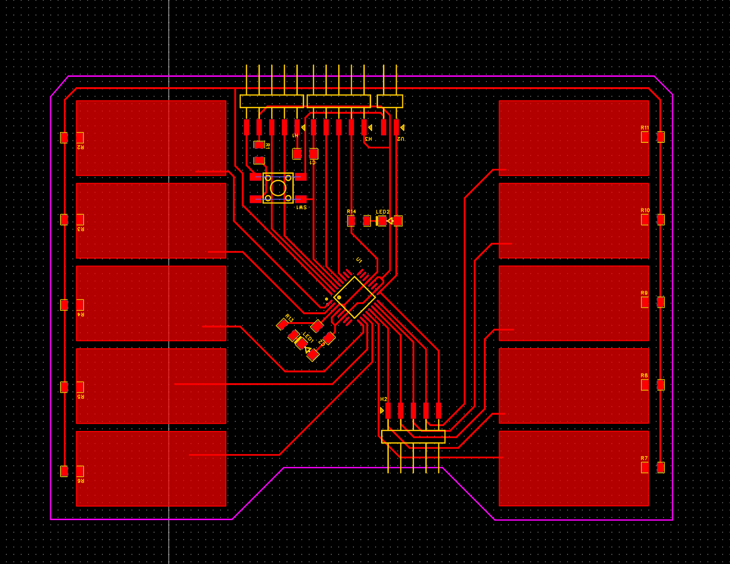
After adjusting some design rules, I finished the wiring and layout of all the components, the gaps between the pins of the chip is at the limit of the size of our end mill.
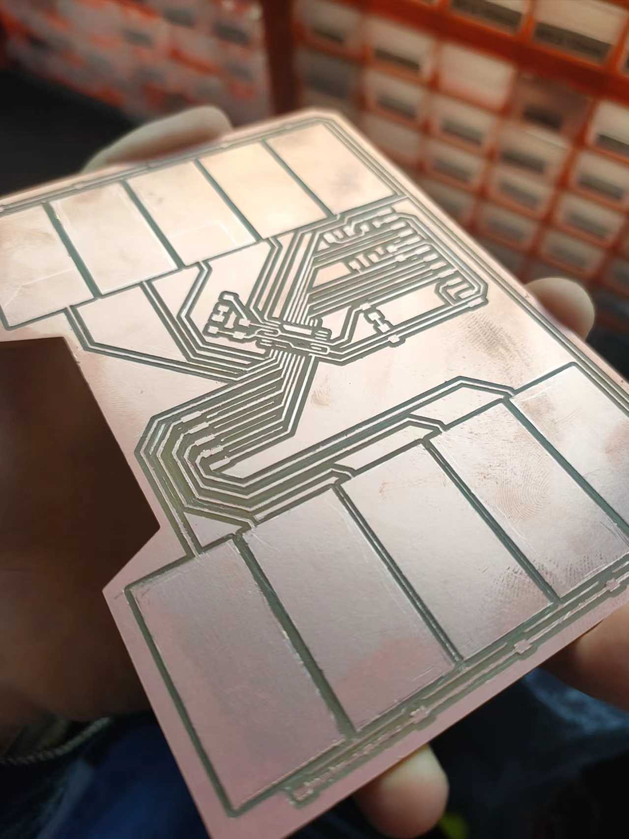
Making
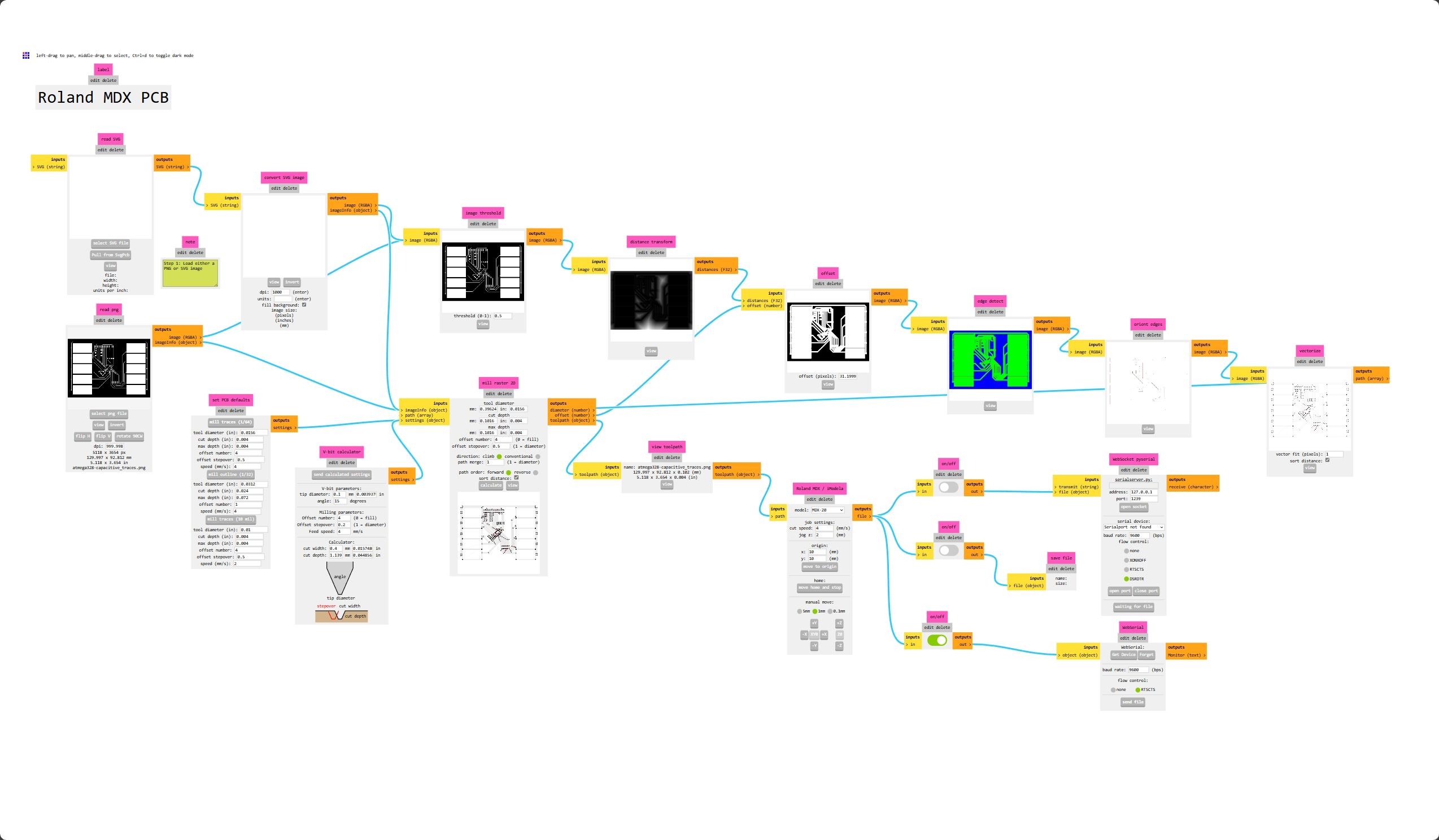
Then I cut the board and soldered the components, I generated the machine tool path using the MODS project as usual. The small package is a bit challenging but I managed to solder anyway.
Bootloader and Uploading Programs
After soldering, I first use the same method documented in week04 to burn the bootloader into the chip. With the bootloader uploaded, I should be able to upload the program through UART just like a regular Arduino boared via a USB to UART converter. But after multiple attempts, I just could not get the bootloader to work, the auto reset circuit on the reset pin seems fine and I couldn't find out what was the problem. My guess is that the Arduino's article on how to burn bootloader by yourself is pretty old and the bootloader file they provided might not be compatible with the current version of the Arduino software.
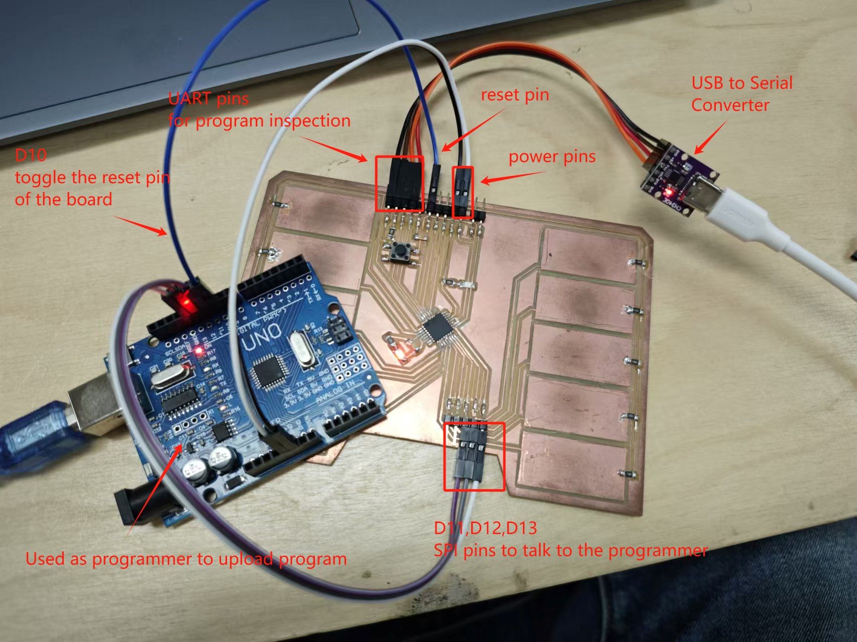
Since I cannot upload program with UART, I can still upload with a programmer. With the following wiring setup, I can upload program through the Arduino Uno and view the serial output from the UART converter board.
Uploading program:
Debugging the connection
With the test programs I found that some of my capacitive input pins was not working. After measuring some connections on the board, and the resistance between some input pins and pin2, I found that the pins that were working have a lower resistance on the two ends of the 1Mohm resistor they were connected to, possibly due to they were connected in parallel with the internal resister inside the chip. As for the pins that were not working properly, they were measured to have 1Mohm resistor across the two sides of the resistor, indicating they were not connected to the chip.
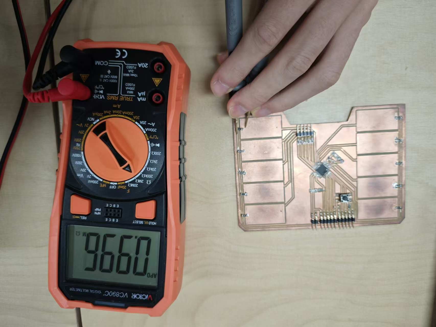
The pins were tested with the connection test with the multimeter, but they were still unconnected, the pins of the chips were too small to be tested directly on them with the pro be. After reflowing some of the pins with the soldering iron, the board was working properly.
Test Program
The program utilizes an Arduino library called capacitive sensor, it allows to use any two pins on the board to form a capacitive sensor between them. There's an article on arduino.cc explaining how the library works. As shown in the schemetic, I have the output pin and the recivng pins wired and the library is measuring the state swiching time on the receive pins.
In the code, I first sets up the CapacitiveSensor instance for each sensing
pin, with all of them sharing a send pin (pin 2). It then constantly reads all
the values from the sensor and if any one of them is above the threshold the
LED is lit.
#include <CapacitiveSensor.h>

CapacitiveSensor pads[] = {
  {2, 3}, {2, 4}, {2, 5},
  {2, 6}, {2, 7}, {2, 8},
  {2, 9}, {2, 10}, {2, 11},
  {2, 12},
};
#define array_len(a) (sizeof(a)/sizeof*(a))

void setup() {
  Serial.begin(9600);
  pinMode(13, OUTPUT);
}

void loop() {
  unsigned long start = millis();
  bool touched = false;
  for (int i = 0; i < array_len(pads); ++i) {
    long val = pads[i].capacitiveSensor(30);
    Serial.print(i);
    Serial.print(": ");
    Serial.print(val);
    Serial.print("\t");
    if (val > 200) {
      touched = true;
      break;
    }
  }
  Serial.println();
  Serial.println(millis() - start);
  digitalWrite(13, touched);
}
Source files
-
Capacitive touch PCB ATmega328p:
- PCB schemetic: 100-schematic.jpg
- board PNG files: atmega328-capacitive_traces.png atmega328-capacitive_outline.png
-
Test Code:
- Arduino library: CapacitiveSensor
- Arduino program: atmega328-capacitive.ino