4. Electronics Producton
This week we learn how to make our own circuit boards.
Assignment
-
Group assignment:
- Characterize the design rules for your in-house PCB production process: document feeds, speeds, plunge rate, depth of cut (traces and outline) and tooling.
- Document the workflow for sending a PCB to a board house
- Document your work to the group work page and reflect on your individual page what you learned
-
Individual assignment:
- Make and test a microcontroller development board
Group assignment
This week's group assignment we tested the charactistics of the milling machine we use - a Roland MDX-40, and using it to cut our first in-house PCB.
We tested the performance of the machine under different spindle speed and feed rate and examined the result, and recorded the optimal parameters for the machine.
We failed to cut some of our boards due to the wrong settings of the spindle rate and the bad endmills, and we found out the right procedure to produce the best results for the cut.
Link to this week's group assignment page.
Atmega328p Development Board
For the dev board, I'd like to have the ability to recycle the microcontroller, but we don't have the suitable female connectors for the board, so I deciced to make a dev borad for the atmega328p controller, since we have the sockets for them.
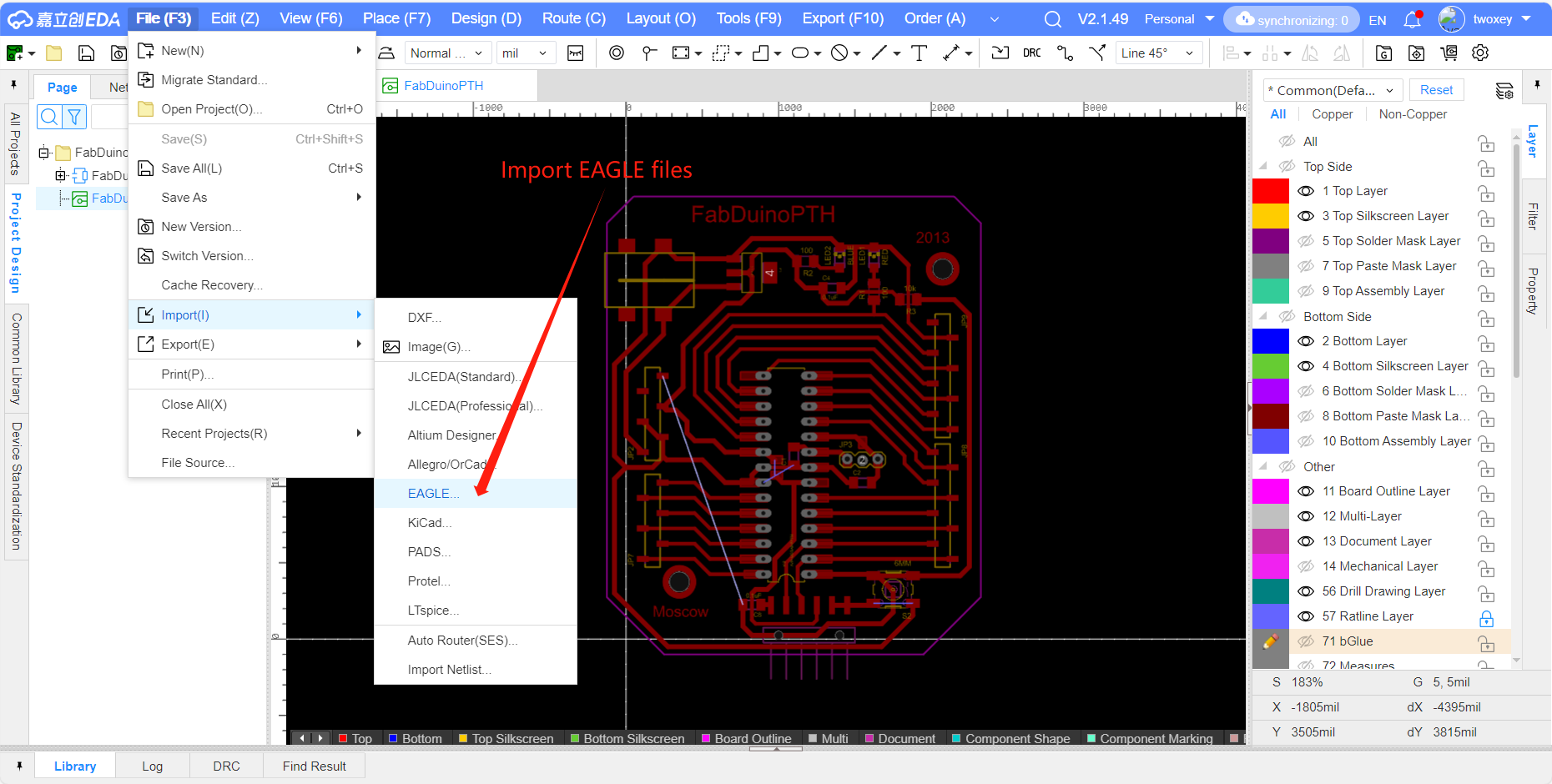
So I went off to search for a dev board that can be used for the atmega328p controller, and I found this one on Google. Looks nice to me, and it provides the Eagle design files for the borad, so I downloaded the files and imported in the JLC EDA Software. It's an online EDA software developed by the board manufactor JLC, and it supports loading the Eagle files.
Making the PNG files
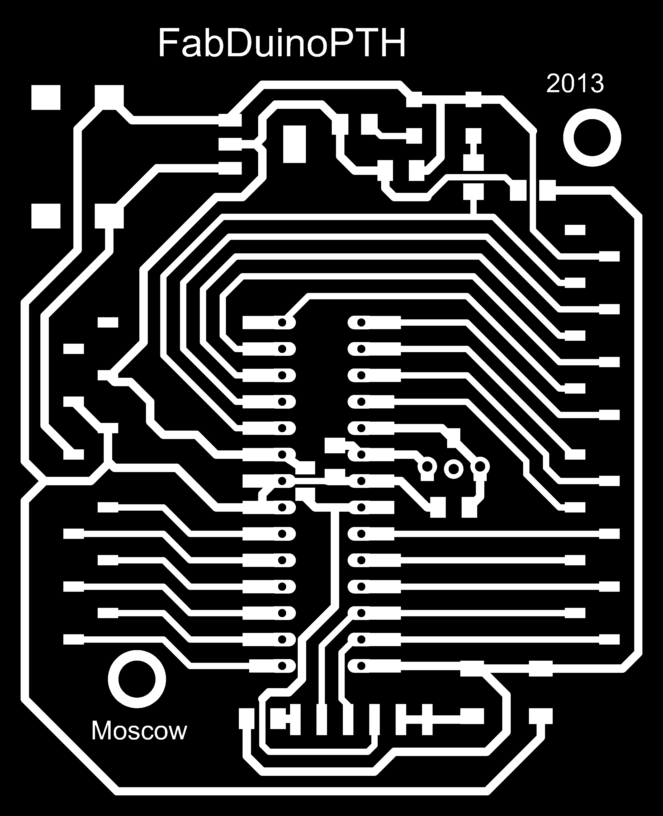
I imported the .brd file and examined it in the JLCEDA editor, and checked it that
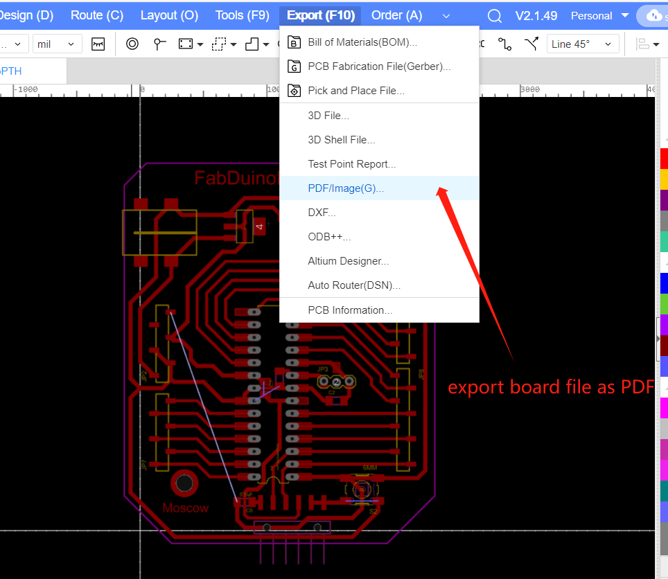
it has no big problem (which turned out to be false later LOL), and I just exported the file as a PDF file.
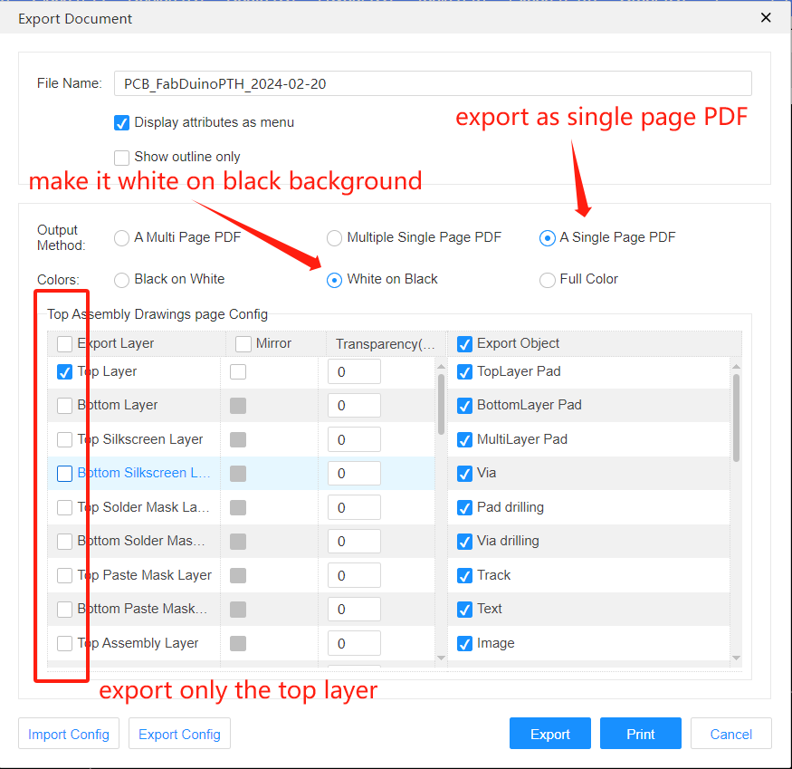
The export option is shown as follow, and we got a file with white traces on the black background.
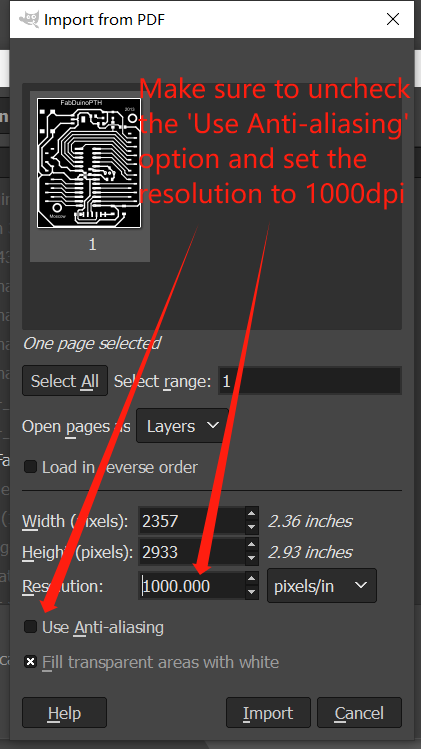
Then I open the PDF file with GIMP to do some additional processing. Here are the steps:
-
Open the PDF file in GIMP and in the import setting, uncheck the 'Use Anti-aliaing' checkbox and set the resolution to 1000dpi to get a high resolution monochrome image to use with the toolpath generation.
-
In the
Image > Canvas Sizetool, resize the canvas to add some padding around the traces, change the unit tommand add the size to image, then click theCenterbutton to offset the layer in the new canvas, and make sure to fill the expanded portion with transparent.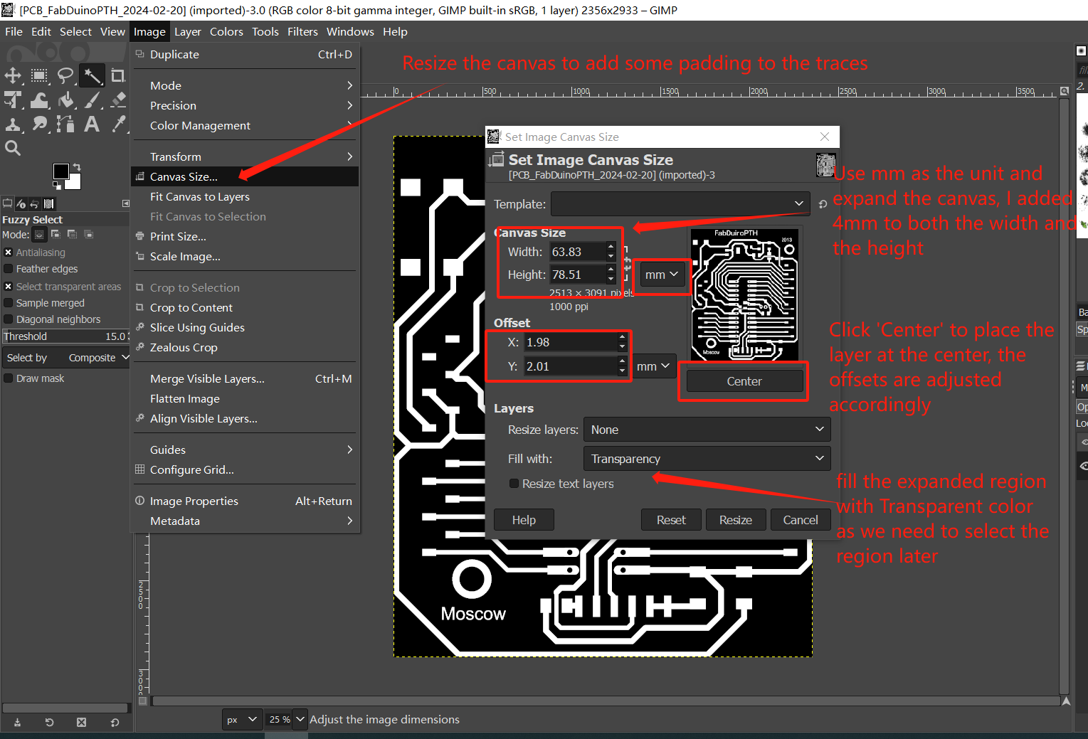
-
Right click the layer to resize the layer to image size, and use the
magic wandto select the trasparent pixels in the layer.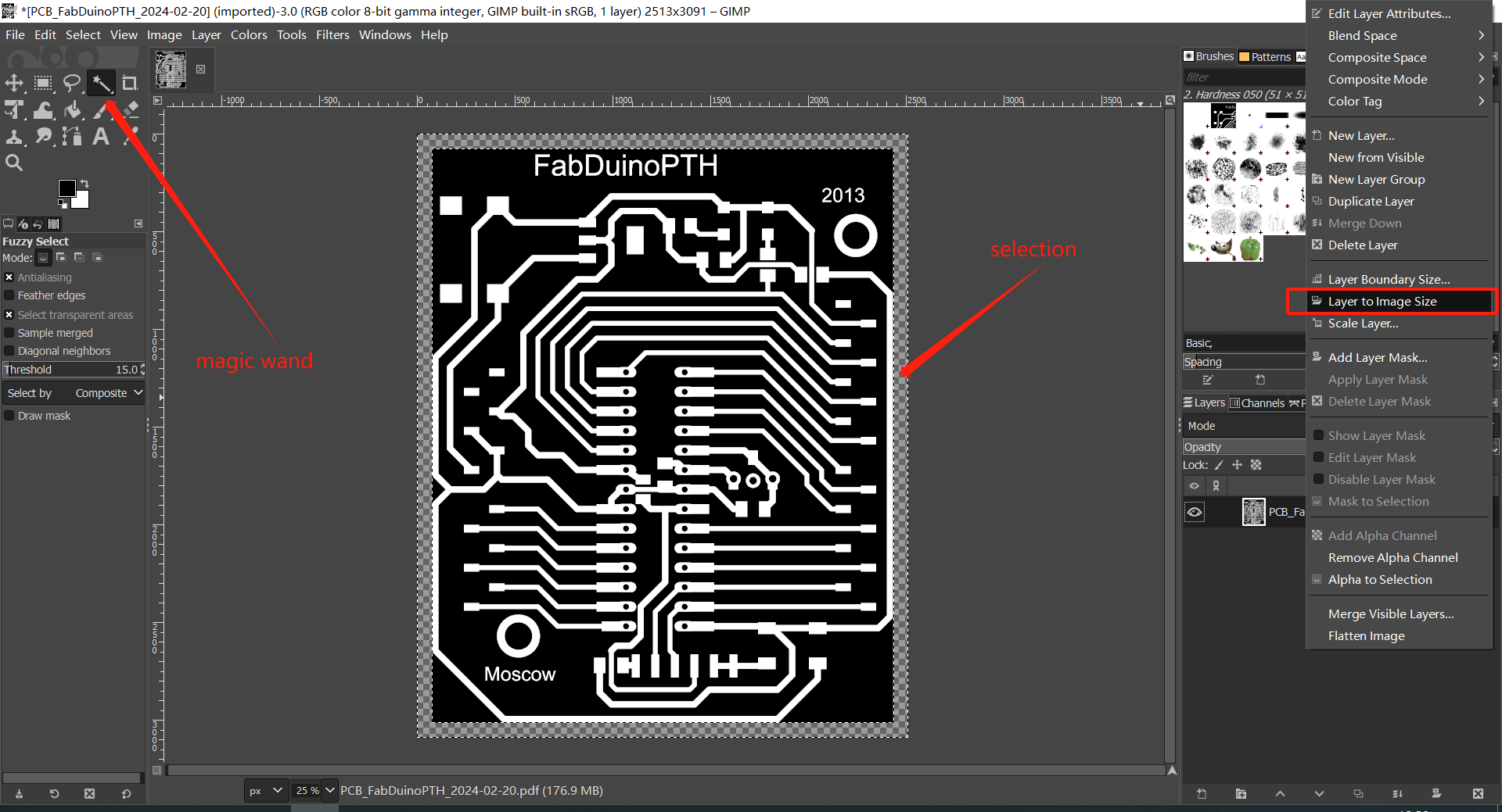
-
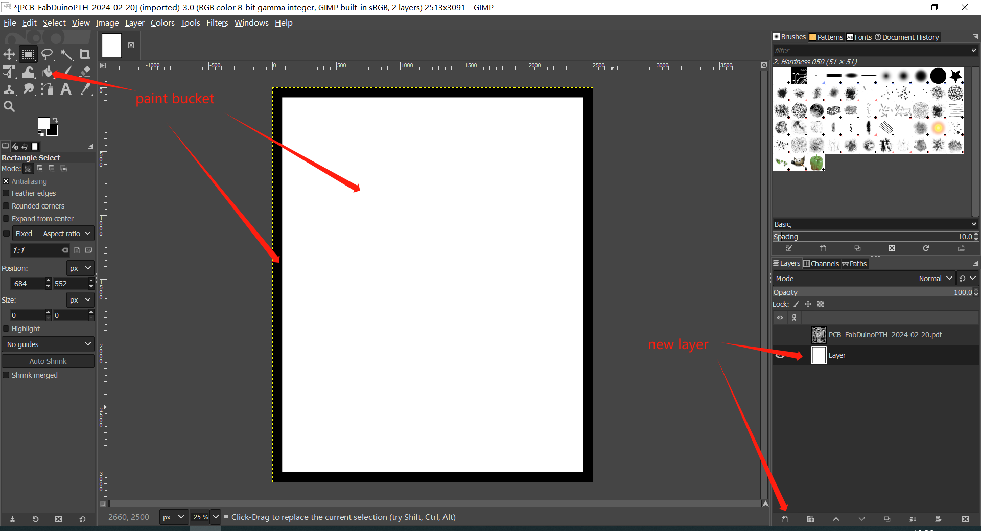
Create a new transparent layer and use the
paint buckettool to fill the selected outer portion with black, then invert the selection and fill the inside with white. Then place the new layer under the traces layer.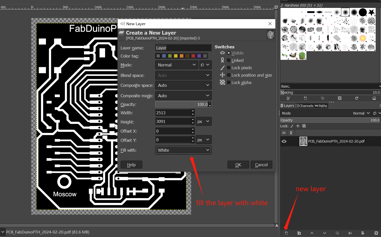
-
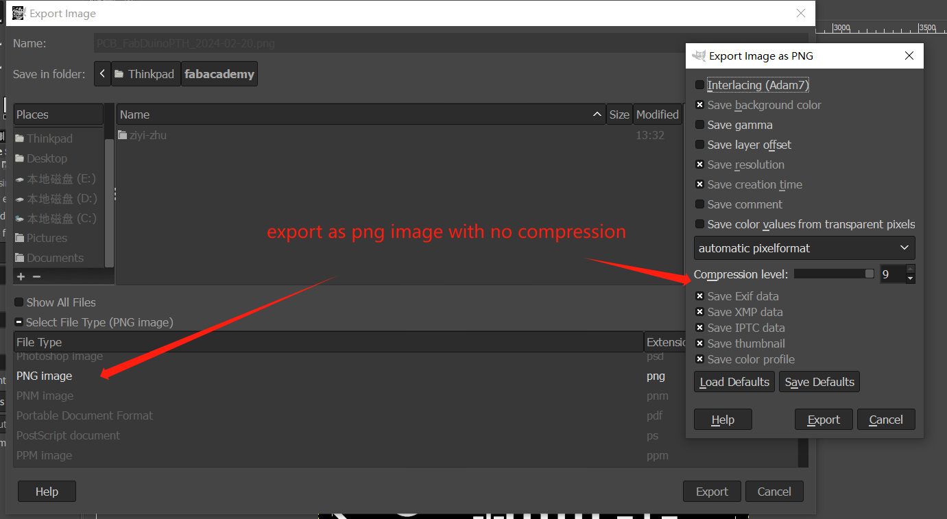
Now export both of the layers as uncompressed png files.
Note: Later it turned out maybe I should add some addtional paddings before filling the board outline, now some of the traces is right on the edge of the board.
Tool path greneration and cutting
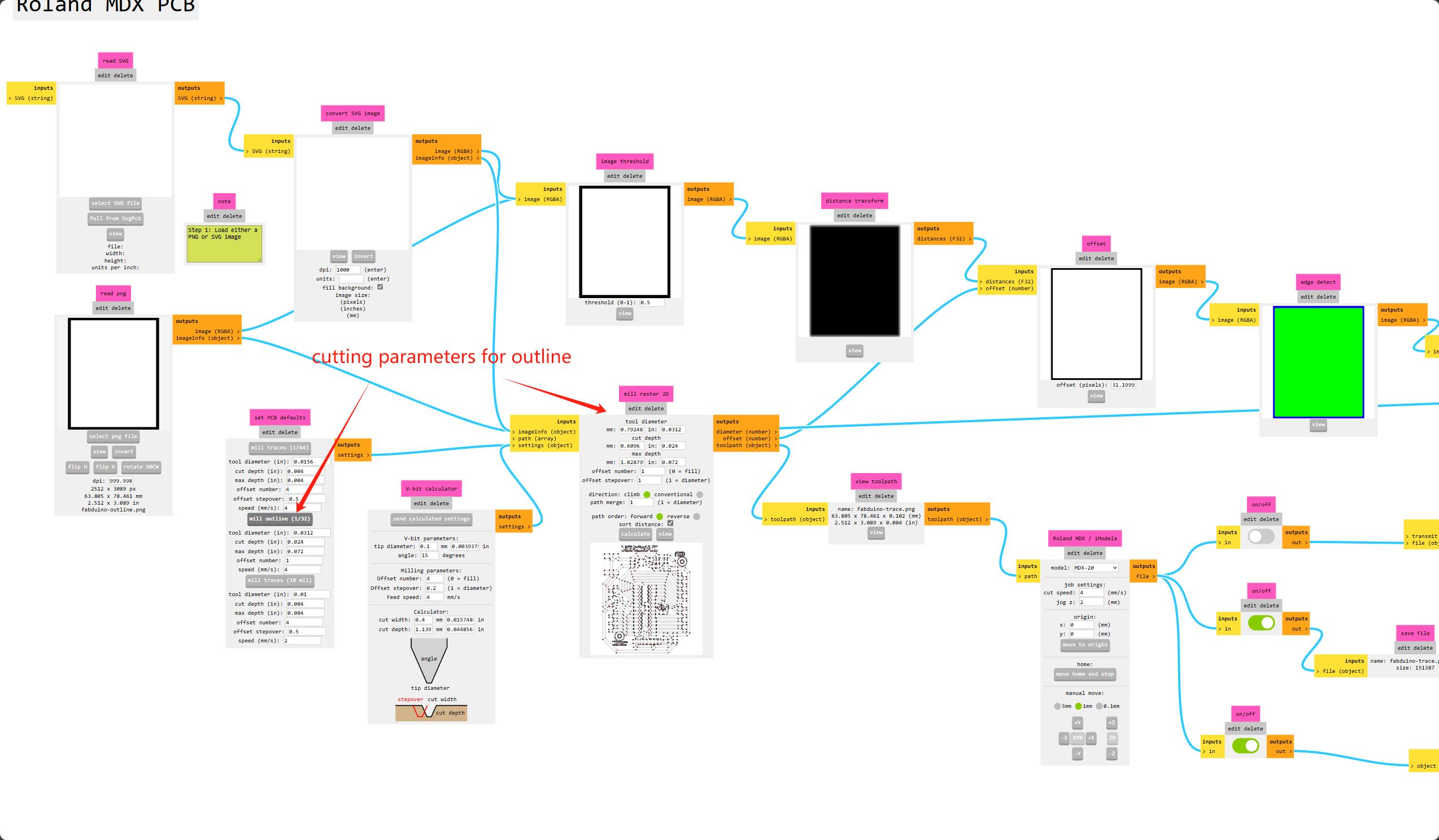
Now we can use the png image to generate tool path for cutting the board, using the Mods Project website.
-
First right click and select
programsthenopen program, then undermachines, because we use the Roland MDX-40 milling machine, selectRoland > MDX mill > PCB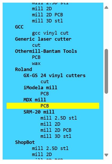
-
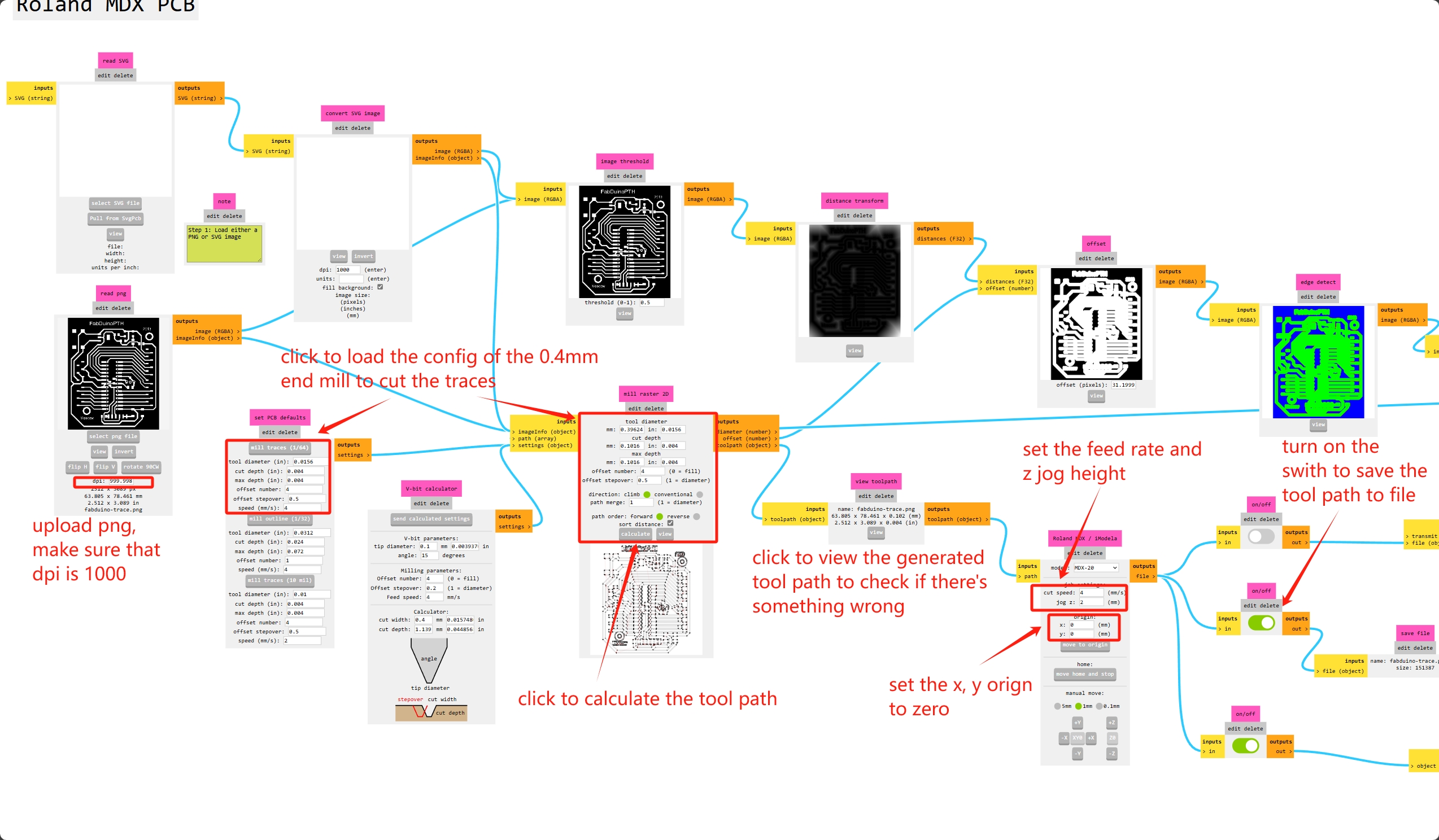
Upload the png file for the traces and set the parameters for cutting the traces, we are using the 0.4mm end mill with 4mm/s feed rate.
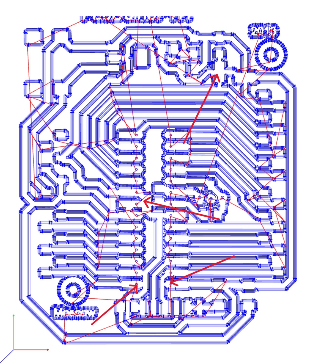
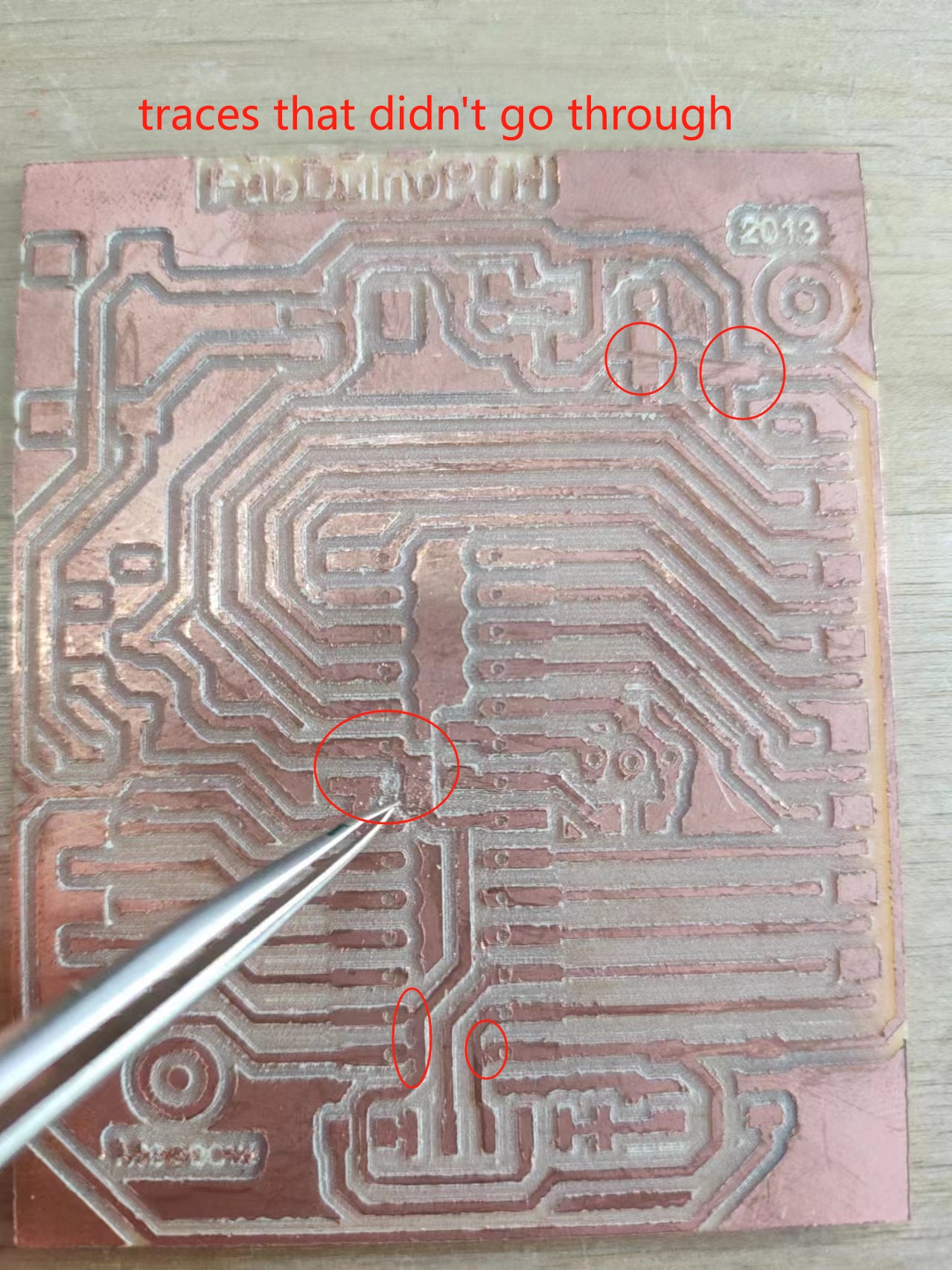
Note: the marked gaps in the tool path are too narrow to let the end mill to go through, thus they are connected, but I was not able to spot that when I first cutting it, leading to me having to cut the traces with a knife when testing the board.
-
Then generate the tool path for the board outline with the parameters for the 0.8mm end mill.
Cutting
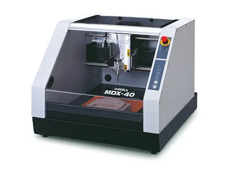
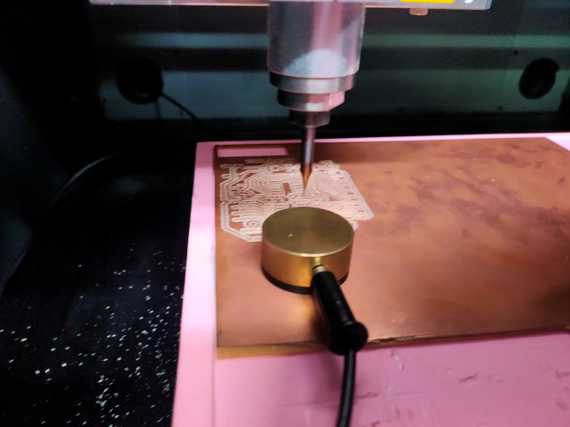
I cut the board with the Roland MDX-40A milling machine, with it's Vpanel control software, I can upload the generated tool path.
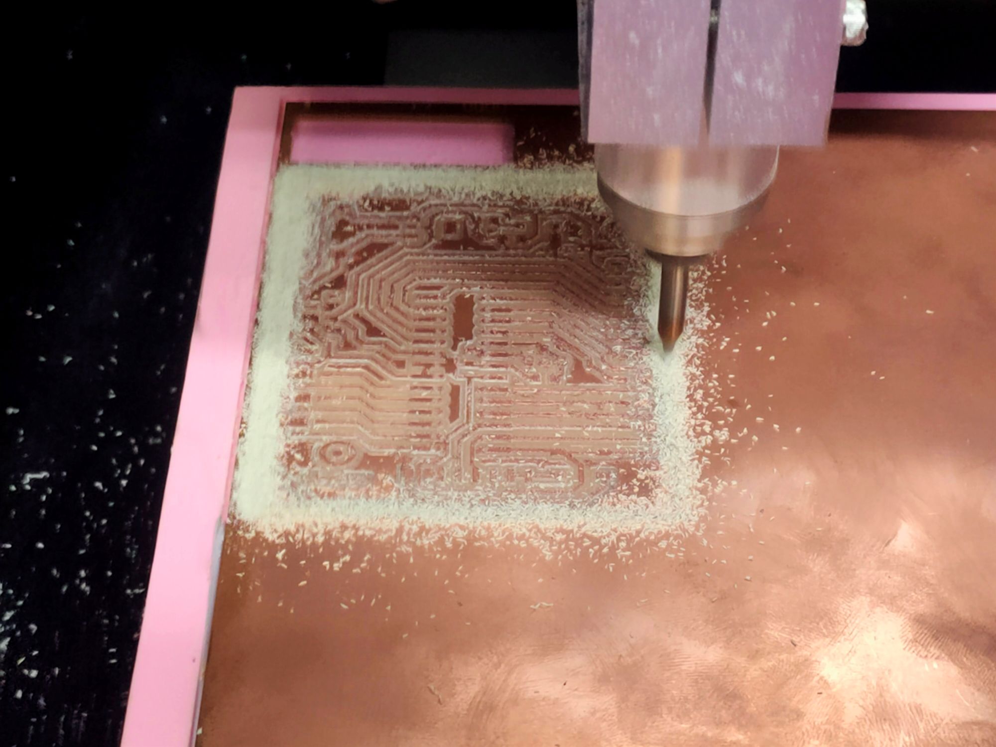
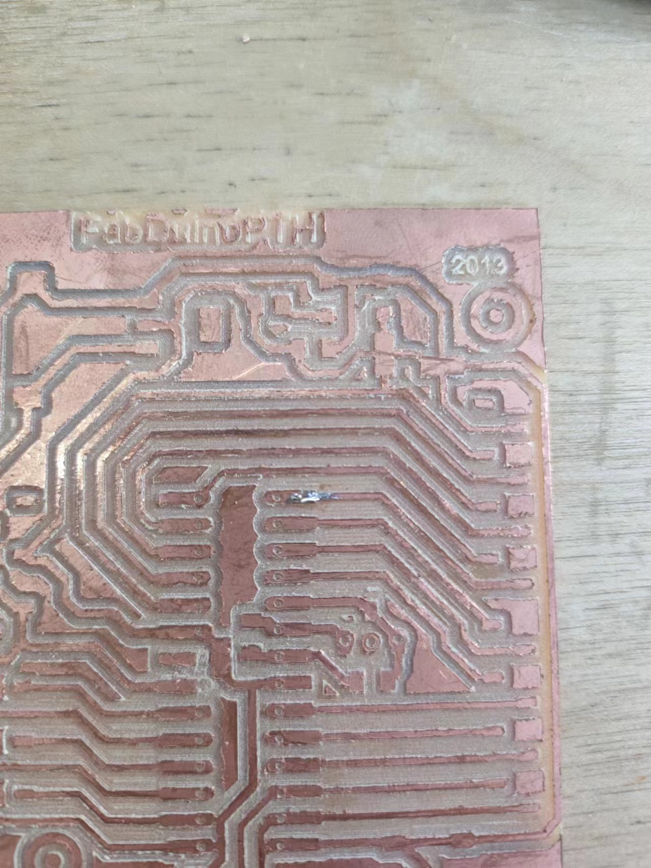
First cut the the traces with a 0.4mm end mill, but because the bed of the machine is not perfectly level, and the PCB is a bit large, first pass didn't cut all the traces.
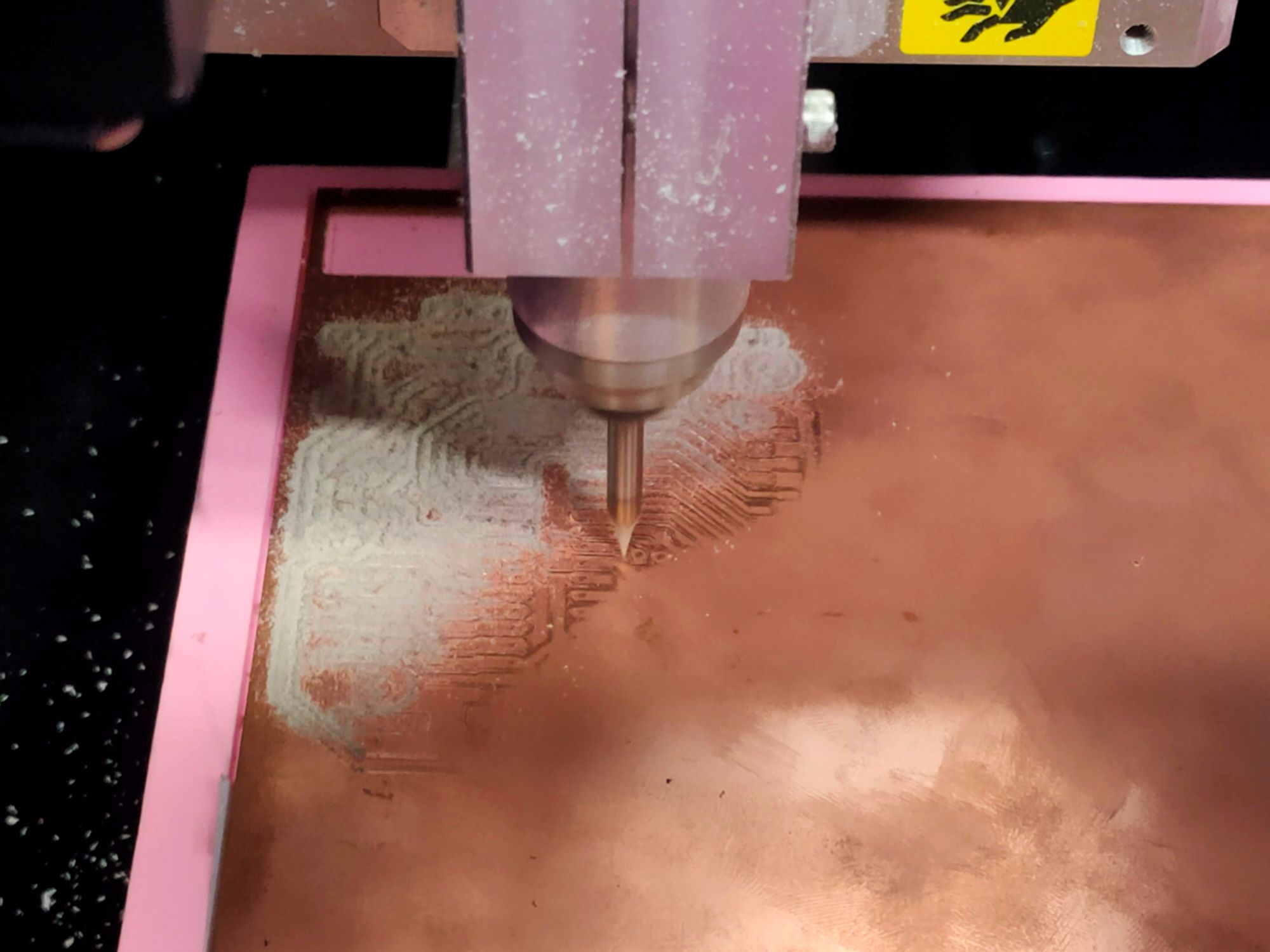
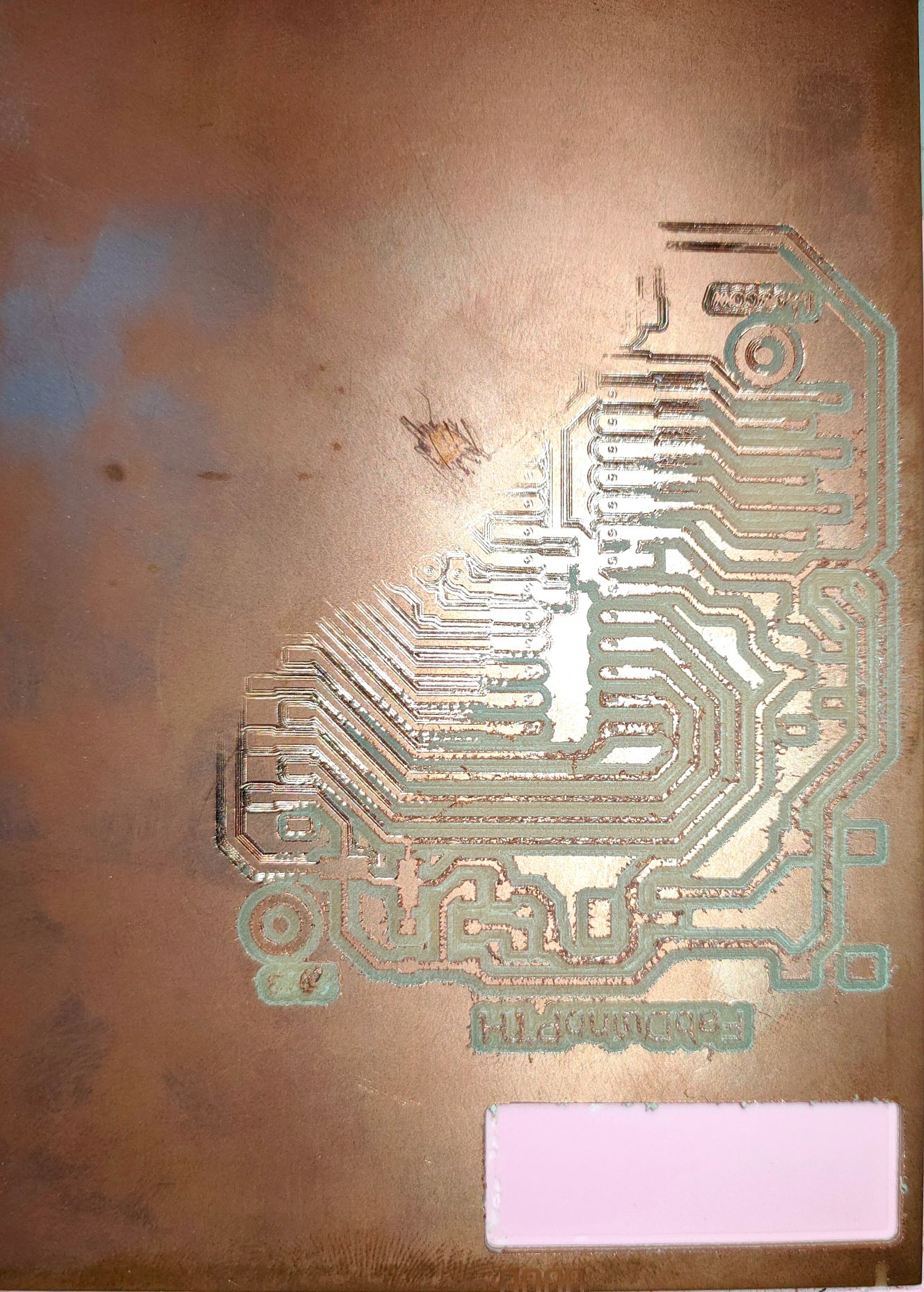
So I did the z zeroing again at at the bottom right corner where the traces were not cut, and ran the tool path again. This time the board was cut.
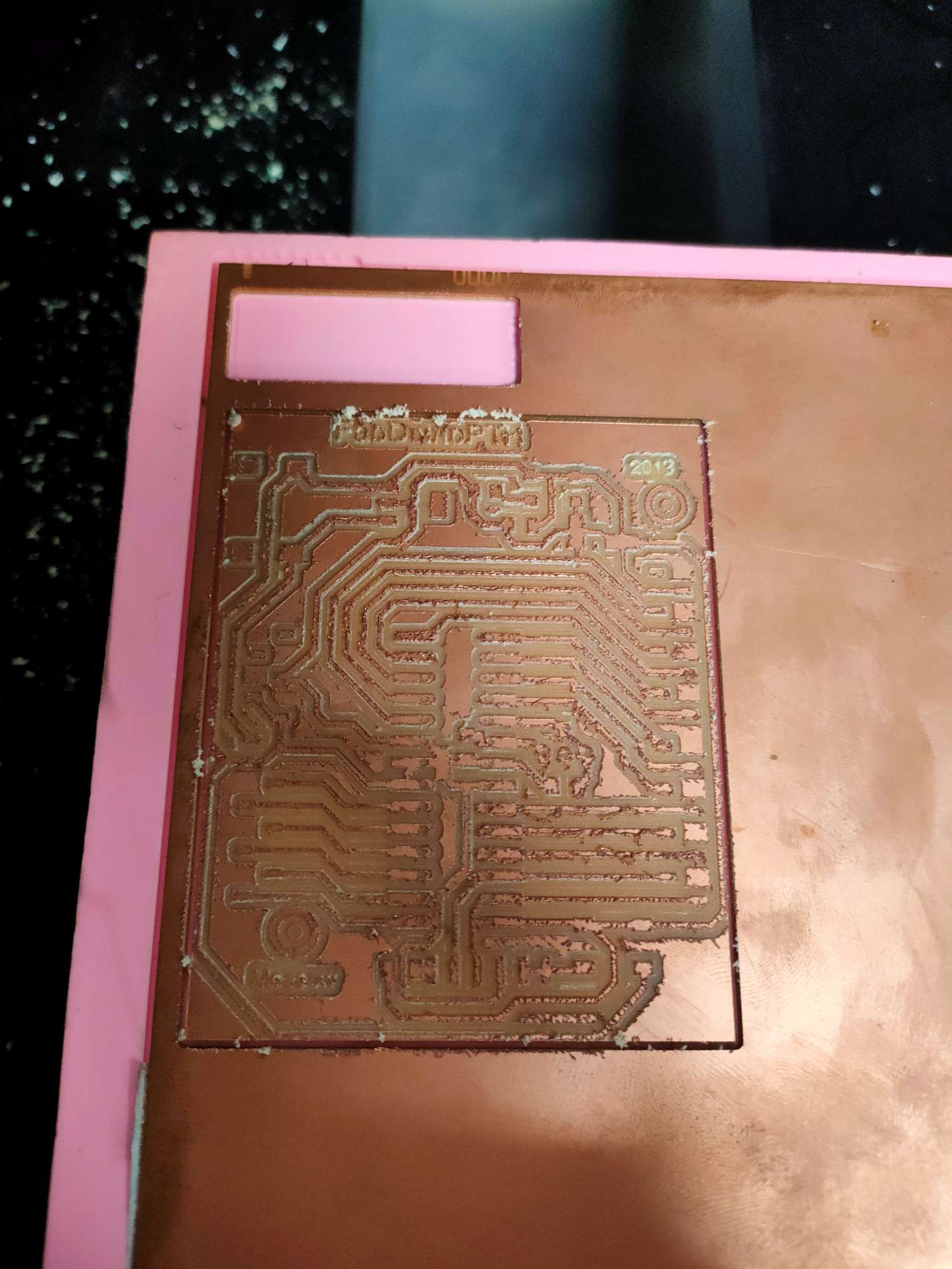
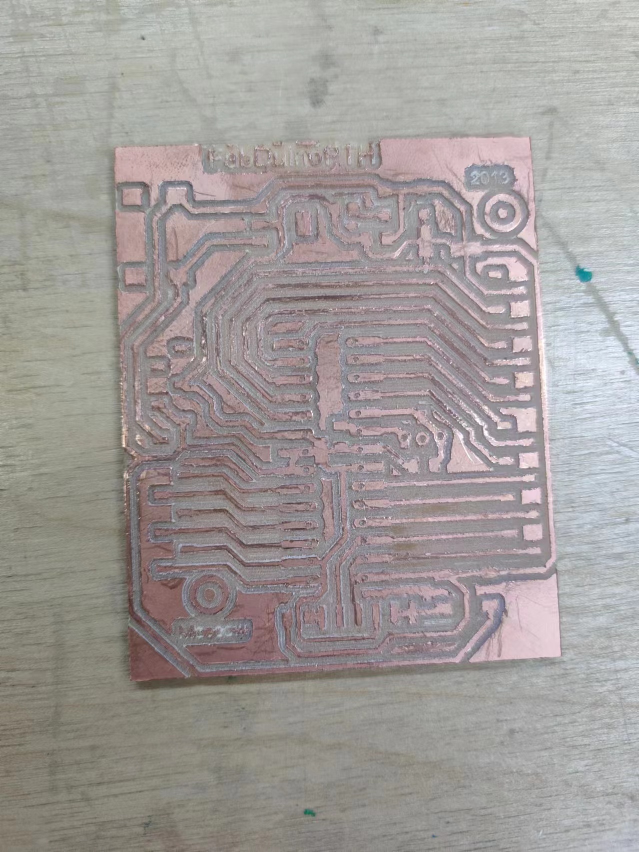
The end mill we used for cutting is a little bit wore off so the edge of the traces were not very clean, but after cleaning the traces with a metal ruler, the board is ready.
Soldering and Testing
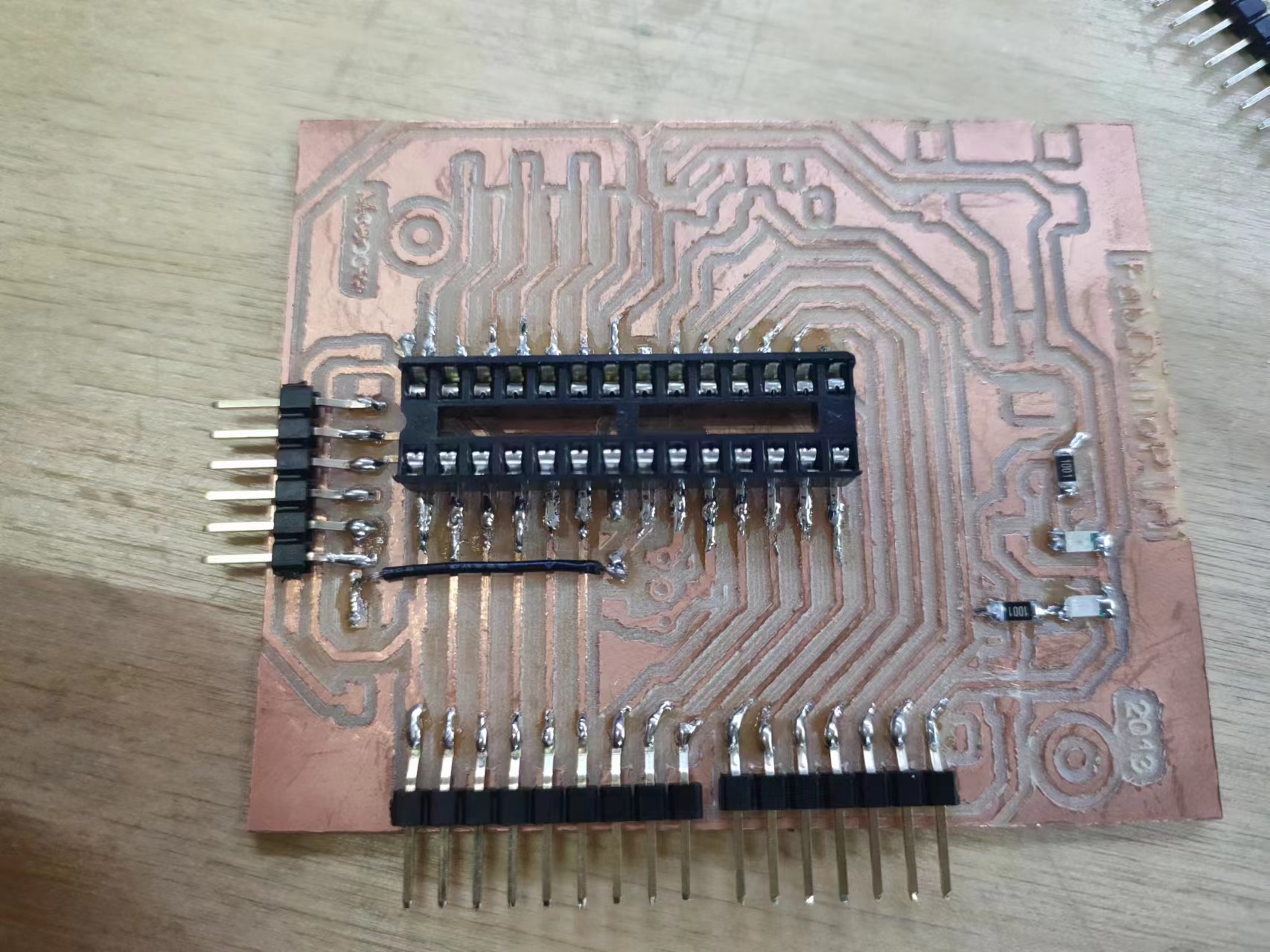
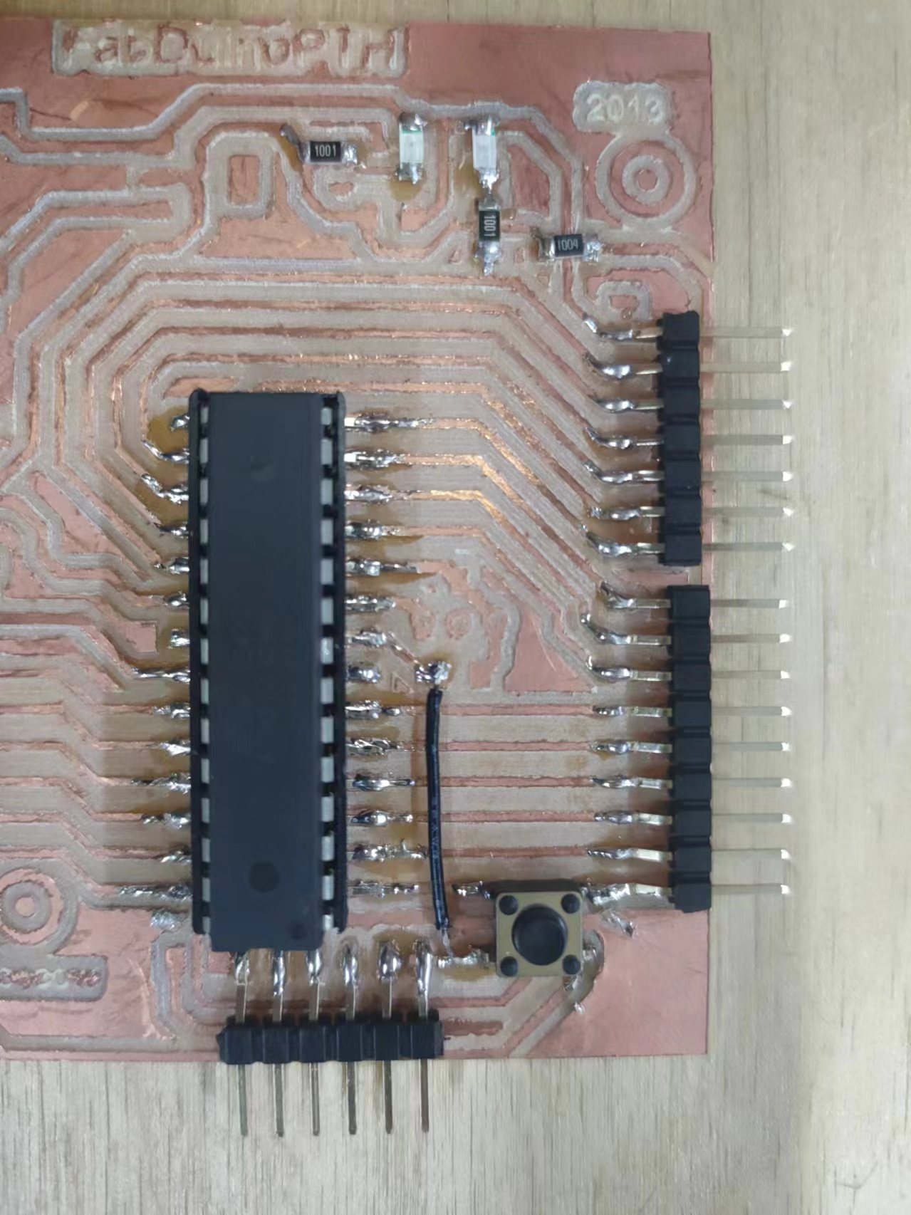
Now I've got my board cut, it's time to solder it!
I examined the board and I found some of the gaps in the design weren't wide enough and the end mill didn't go throungh. So I have to fix them by cutting them using the utility knife. The lesson I learnt here is that I should've set some design rules before exporting the images from the EDA software to let it check the errors for me first.
The Arduino Uno also has an Atmega328 at its core, so in theory my board can run the same program as an Arduino Uno can, the only difference is that the Uno has an extrenal 16Mhz crystal osillator to make it run at a higher frequency. The board I dev board I cut also designed the place to put the crystal and the capacitors it needs.
But unfortunately, I checked that we have the crystals in stock the day before I cut the board, the next day, they were gone :( . But I came up with another solution, that is to use the Atmega328's internal oscillator.
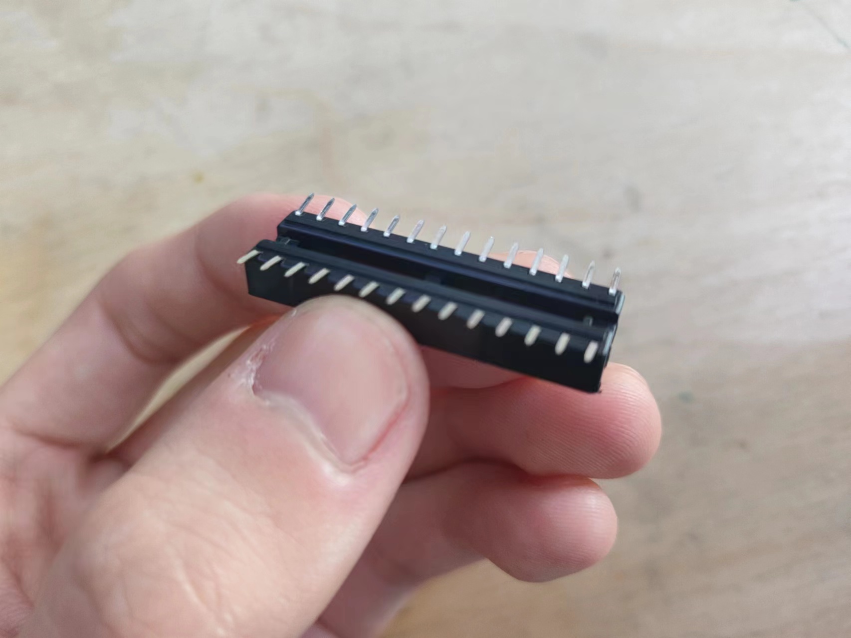
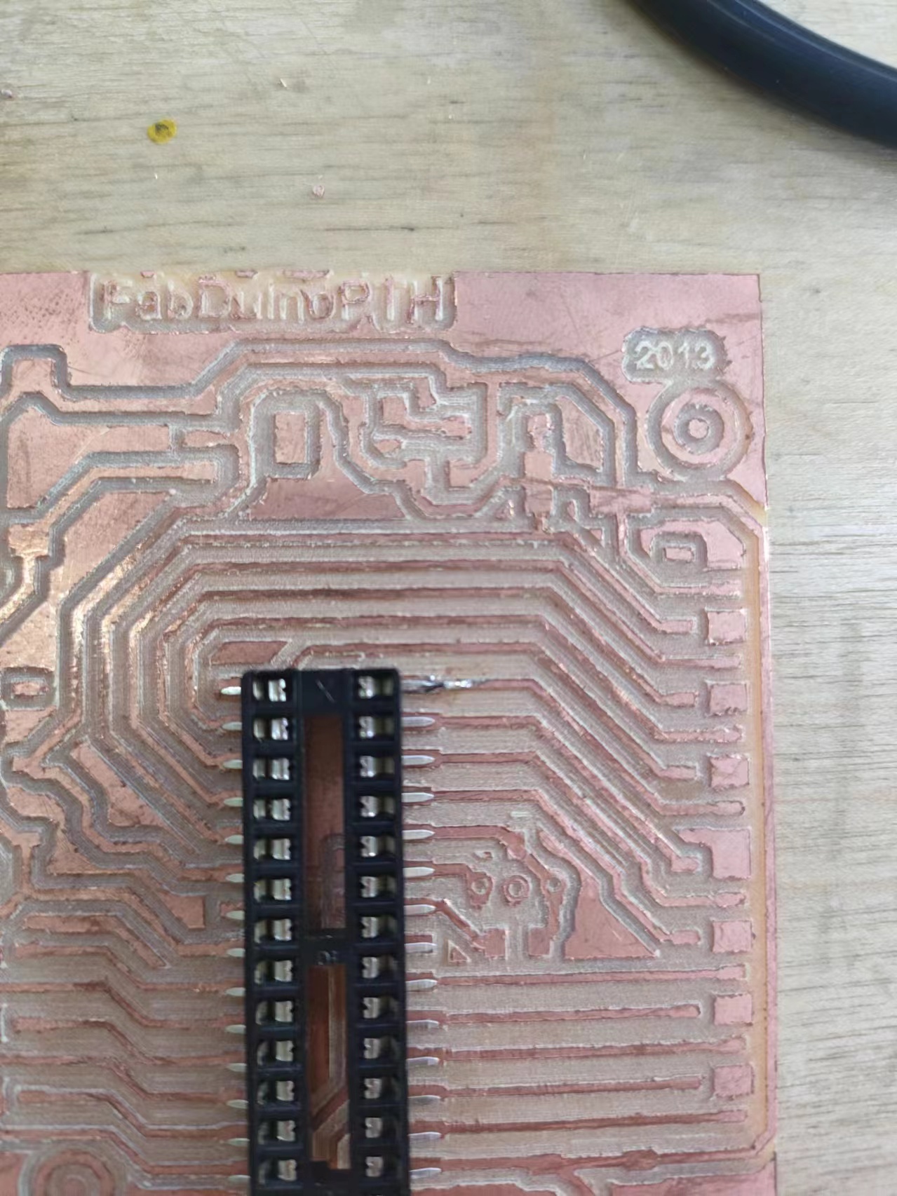
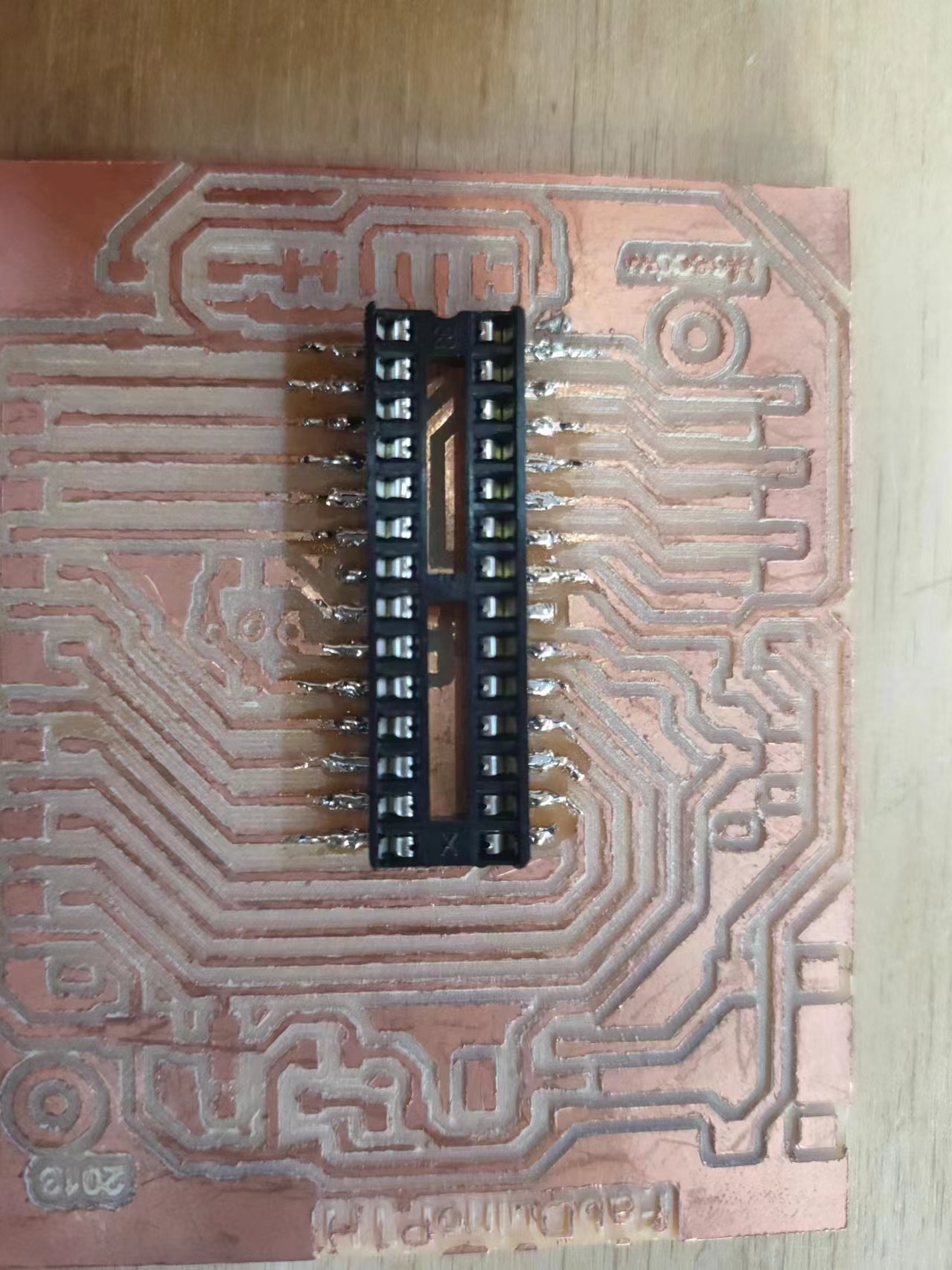
So I did't put the crystal and the capacitor that is under the socket, just started to solder the socket. The socket is a through hole component orignially, but it can be bent easily to make it SMD.
Then use the soldering iron to put a little bit of tin on the first pad for the socket, then solder the first pin of the socket to prevent it from moving. Then do it on the opposite side, then solder all the pins one by one.
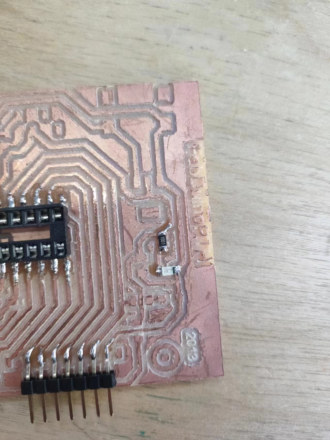
Then I soldered the power led and its current limiting resistor, and some of the pin headers to test the traces. And connected the 5V and GND pins to test if everything is fine. The power led is working.
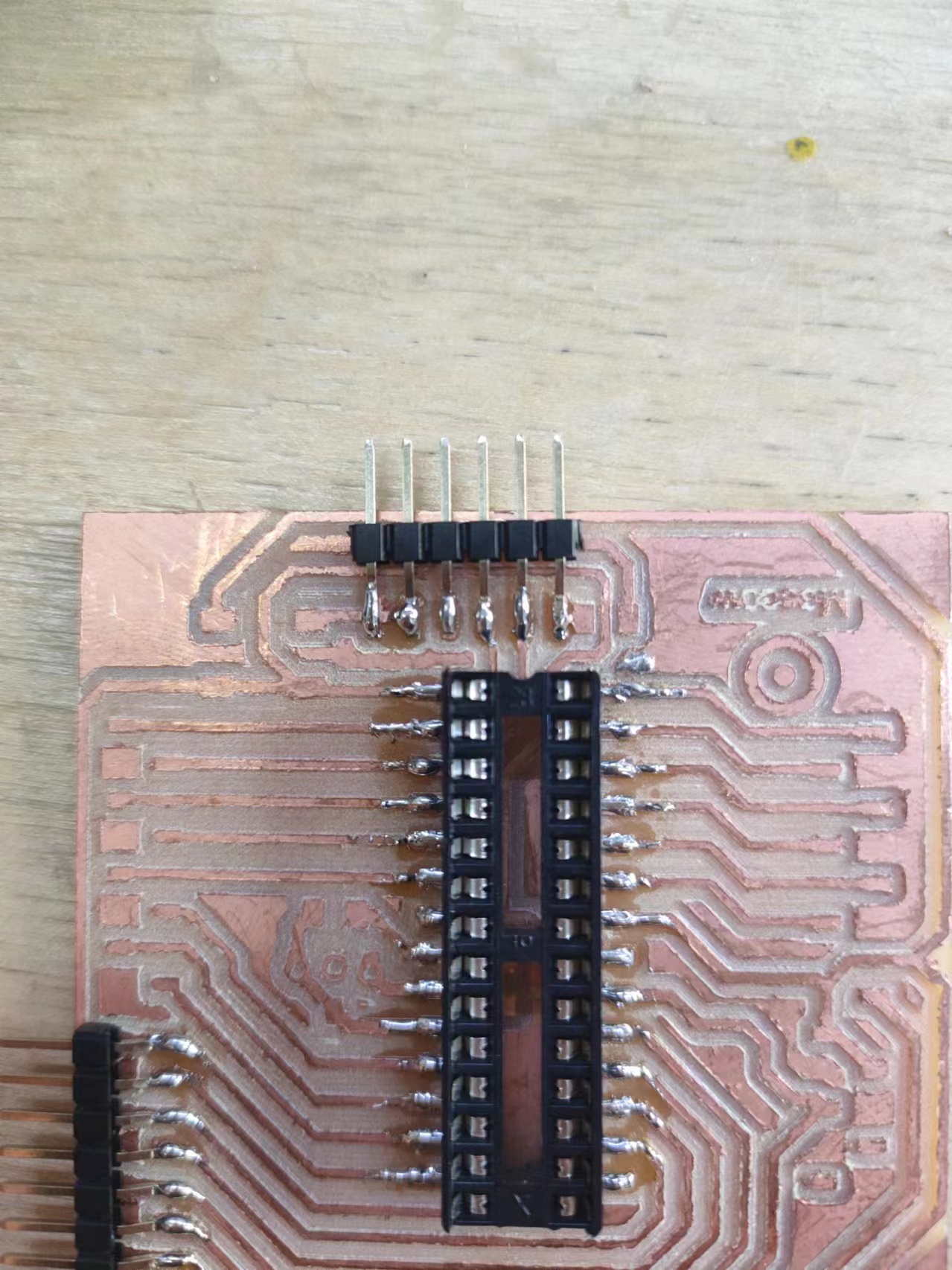
Then solder the other pins to test the board.
The atmega328 without the crystal needs a different profile than the Arduino Uno to upload the program. I founded this tutorial by Arduino to upload code to a bare atmega328.
First download the board config for atmega328,
create a folder called hardware in the Arudino project folder (defaults to My Document > Arduino on Windows),
extract the downloaded board confige into the folder.
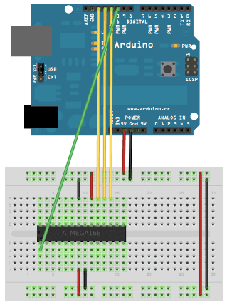
We need a programmer to program the atmega328p chip, and an Arduino Uno can be used to emulate a avr programmer.
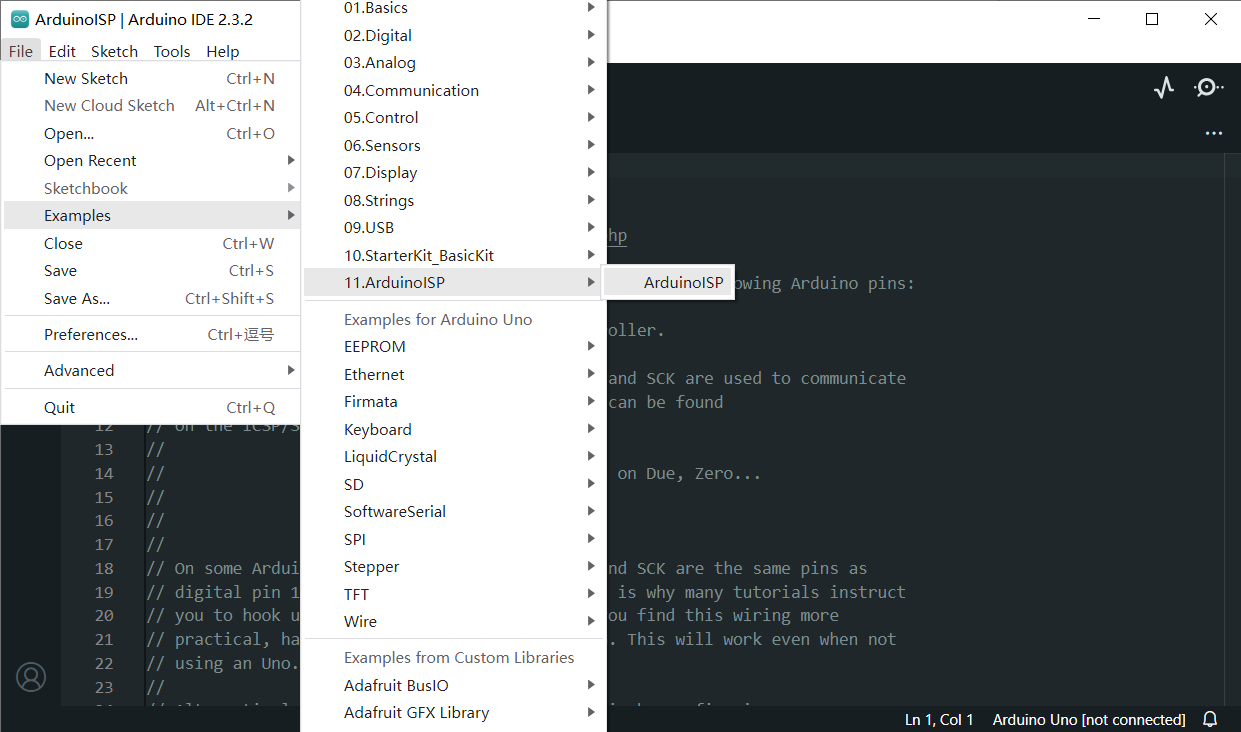
Open the Arduino IDE software and select the File > Examples > 11.ArduinoISP > ArduinoISP and upload the sketch
to an Arduino Uno. Now the Uno can act as a programmer to program the other atmega chip.
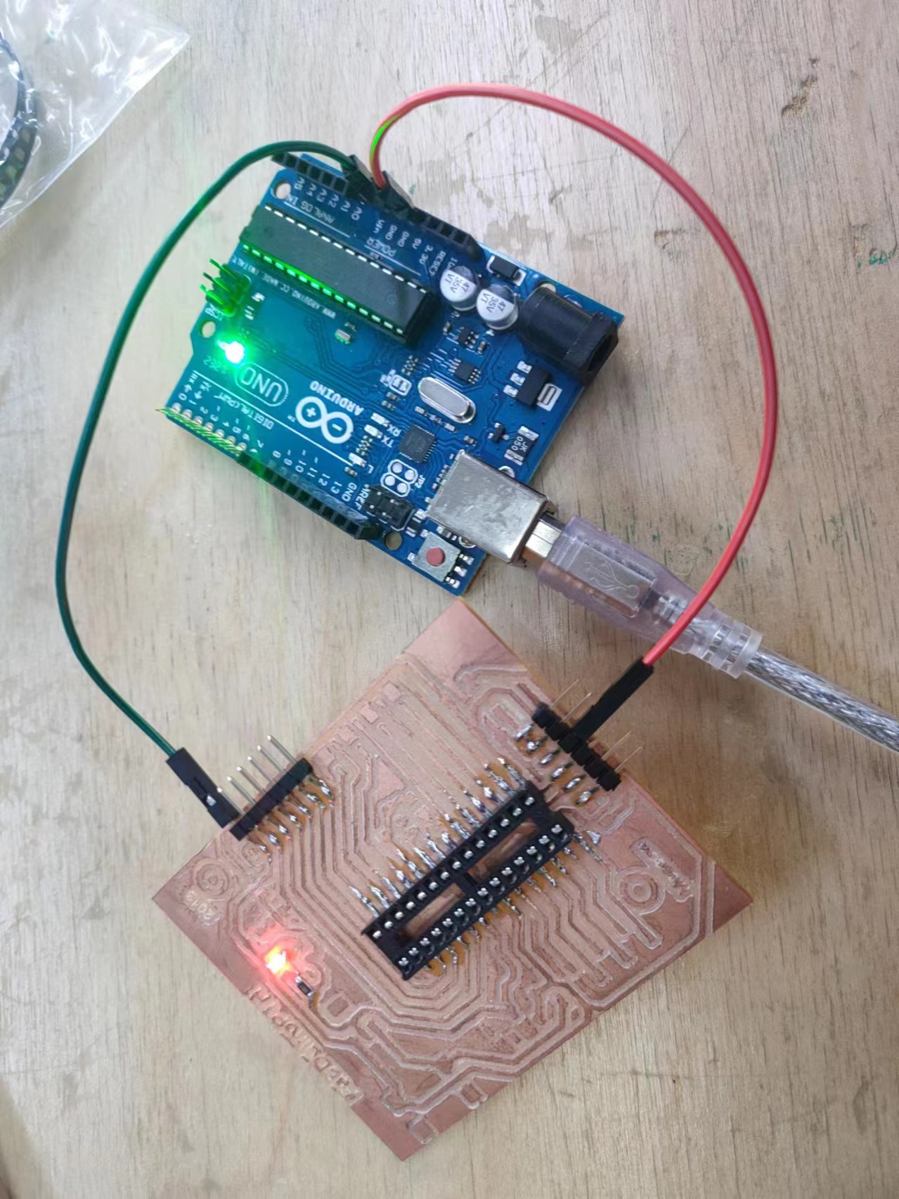
Connect the Uno and 328p like the image below, the Uno can use the SPI interface to program the chip.
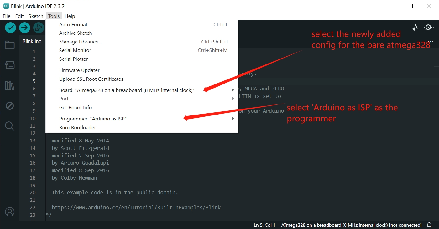
Just try to upload the basic Blink example of Arduino to the atmega, in the Arduino IDE, in Tools > Board menu,
select the ATmega328 on a breadboard(8MHz internal clock) option, and in Tools > Programmer, select Arduino as ISP
as the programmer.
Then goto Sketch, click Upload Using Programmer to upload the program through the Uno as programmer.
After the blinking indecating data transmission, the LED blinks once every second, showing that the program has been uploaded successfully.
The board running with the power pins plugged in.
Finally I solded on the reset button and its pullup resistor.
Project files
- PCB traces: fabduino-trace.png
- PCB outline: fabduino-outline.png