Week 14: Interface and Application Programming 😀!
The fab academy is really at its climax! We have to focus not only on our assignment, but also to our final project. Ohh lord... things are really getting tough and I cant keep up! Even with all these challenges, I will try and do my best to give my best!
Assignments🧐!
Write an application that interfaces a user with an input and/or output device(s) on a board that you made.
The application gui has to be a sort of GUI(Graphic User Interface).
Group assignment.
Compare as many tool options as possible.
Document your work on the group work page and reflect on your individual page what you learned.
Let's begin!
Firstly before anything I really have to plan my approach to this week. My current board which has the attiny 3216 as it main board, doesn't have web sever capabilities. Therefore for my GUI, I have to make through a bluetooth interface.
At first I really didn't have any clue on how I would be able to create a GUI through bluetooth. I was also contemplating on creating a new board which has a micro controller that has wifi capabilities. Then I would be able to utilize the web sever and then simply create my GUI.
But after like in hour of brain storming for like an hour, I found Zina's documentation. She used python with the Tkinter library to create a GUI that could interface over bluetooth. Thank lord! if it were not for this documentation, I don't know what I would have done. But now that I have a way to create a GUI through bluetooth, lets really begin with this weeks assignments.
Testing
Before working with my actual board, let me first test all the codes using an arduino dev board so that I can ensure everything is working according to what was planned.
Lets first set up our arduino board and then our bluetooth module so that I would be able to test out the first iteration of my codes.
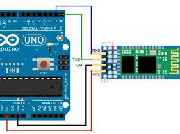
The setup for the HC-05 bluetooth module is pretty self explanatory and also simple. There are four pins in the bluetooth module. two of those pins are VCC and GND pins and the last two pins are RX and TX pins.
Codes
After setting up the arduino board and the bluetooth module I had to start with the programming part of this assignment.
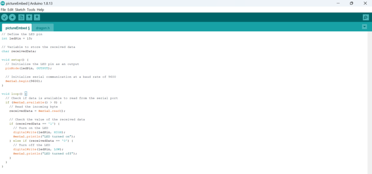
To do that I firstly wrote an arduino IDE code that would be able to read signals that are given by the bluetooth module when I use the GUI from my laptop.
// Define the LED pin
    int ledPin = 13;

    // Variable to store the received data
    char receivedData;

    void setup() {
    // Initialize the LED pin as an output
    pinMode(ledPin, OUTPUT);

    // Initialize serial communication at a baud rate of 9600
    Serial.begin(9600);
    }

    void loop() {
    // Check if data is available to read from the serial port
    if (Serial.available() > 0) {
        // Read the incoming byte
        receivedData = Serial.read();

        // Check the value of the received data
        if (receivedData == '1') {
        // Turn on the LED
        digitalWrite(ledPin, HIGH);
        Serial.println("LED turned on");
        } else if (receivedData == '0') {
        // Turn off the LED
        digitalWrite(ledPin, LOW);
        Serial.println("LED turned off");
        }
    }
    }
This is a simple code that allows for the arduino dev board to be abel to communicate with the HC-05 module.
To explain a bit about the code, in the code we first have to define two variables ledPin and then the receivedData variable.With these variables set, we next have to set the serial communication between the HC-05 bluetooth module and then we simply write the code; if value that is returned is zero, then led off, if the value returned is one, then led on.
After uploading this simple code to the arduino board, Its now time for me to set up my GUI display using python.
Python
Now following up with Zina's documentation I will have to to download python on my device so that I will be able to use python to make my GUI.
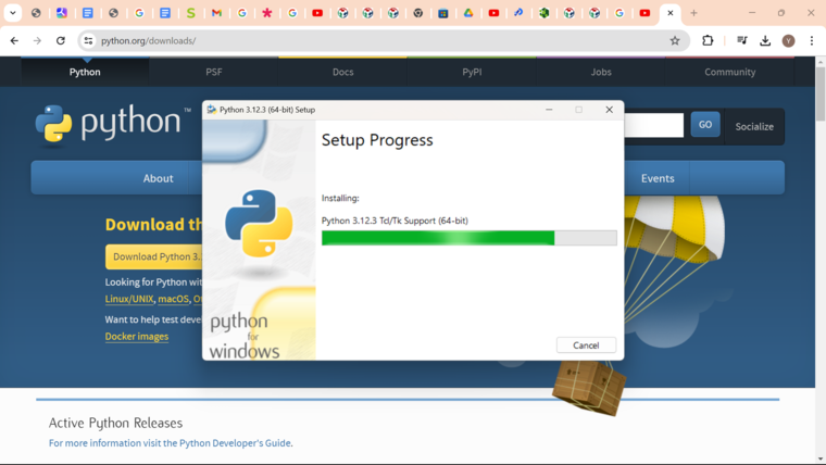
For you to download python, go through this link right here --> Python
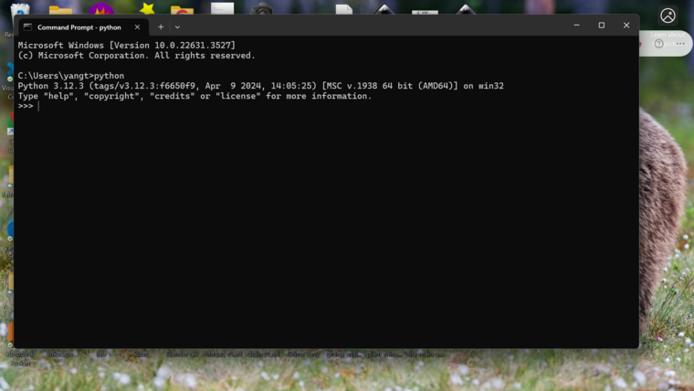
Next I have to check whether I have python properly installed on device or not. For that I need to open up my terminal and then I have to type "python". This command will make the terminal give you the information about the python version you have installed.
Now here is a twist, I will actually be using VScode to write and run my python code. For that we have to install the python extension in VScode.
Now before writing my python code I have to first know which port my bluetooth module had to been connected to.
To do that I have to go to settings and then I have to go to bluetooth and device.
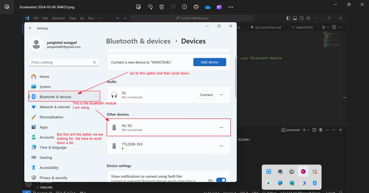
After that we have to scroll down a bit and then I should be able to see the option more bluetooth option.
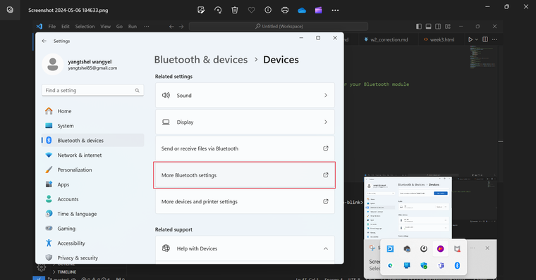
After pressing the bluetooth setting, we can now go to com port and then see which port our bluetooth module is connected to. To determine which port is connected to the bluetooth module, we can see whether the com port has the name of the module or not. With that we also have to see if the port direction is outgoing. We need to clarify the direction to the outgoing port as it is a sort of transmitting port which sends instructions to the bluetooth module, thus sending messages to the main board.
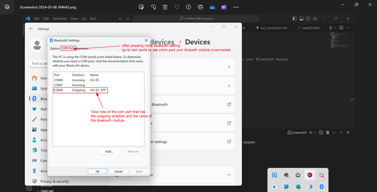
With that we can finally start with writing the code for the GUI.
GUI
Now that we are finished with most of our work. We only have to write the GUI python code for the
import tkinter as tk
from tkinter import ttk
import serial
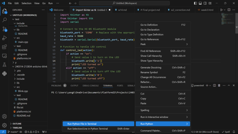
# Connect to the Bluetooth module
bluetooth_port = 'COM8' # Replace with the appropriate port name for your Bluetooth module
baud_rate = 9600
bluetooth = serial.Serial(bluetooth_port, baud_rate)
# Function to handle LED control
def control_led(action):
if action == "on":
# Send value 1 to turn on the LED
bluetooth.write(b'1')
print("LED turned on")
elif action == "off":
# Send value 0 to turn off the LED
bluetooth.write(b'0')
print("LED turned off")
# Create the main window
win = tk.Tk()
win.title('LED Control')
# Create a label for LED control
led_label = ttk.Label(win, text='LED Control', font=('Arial', 18, 'bold'))
led_label.pack()
# Function to handle LED on button click
def led_on():
control_led("on")
# Function to handle LED off button click
def led_off():
control_led("off")
# Create a button to turn on the LED
led_on_button = tk.Button(win, text='Turn On LED', command=led_on, width=20, bg='green', fg='white')
led_on_button.pack()
# Create a button to turn off the LED
led_off_button = tk.Button(win, text='Turn Off LED', command=led_off, width=20, bg='red', fg='white')
led_off_button.pack()
# Run the main loop
win.mainloop()
This is a simple code that is able to turn on and off an led. It also creates a gui that has two buttons that have the option "led on" and "led off". After running the code lets hope that it works.
The code I used is heavily inspired form Zina Yonten's week 14 interface and application week! Her code really help me understand tkinter. Also my code is really similar to hers except I used an additional HC-05 module with which I made the the python code pair up with a bluetooth COM port.
TKinter
Lets also talk about TKinter, the library that I used to create the GUI. Firstly TKinter is an inbuilt library that allows for python users to create Graphic User Interface. It's a really cool library that allows for us to create buttons, text boxes and more!!! The gui can also give out put which can be received by external micro controller through various communication protocol such as Serial communication or like I did through the use of a bluetooth module.
In the provided code, the Tkinter library is used to create a GUI for controlling an LED through a Bluetooth module. The code imports the necessary libraries, establishes a connection with the Bluetooth module, and creates the main window. It includes functions to handle LED control and defines buttons for turning the LED on and off. Tkinter simplifies the process of creating a GUI in Python, allowing developers to easily design interactive interfaces for their applications.
Now lets run our code to see if it works or not!
Hero Video with arduino!
With my board!
Next we have to do all the connections with my own micro controller board. That will be simple enough as no problems had arisen while doing it with the arduino. Therefore if I correctly redo the procedure with my board, it should work!!
After changing the arduino code a bit by changing the led pin to pin 3 as this is led pin for my board.
int ledPin = 13;
With that I uploaded the same python code and then redid everything.
Pin configuration
This is the pin configurations with my board.
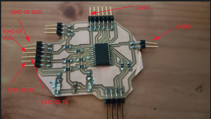
GND: This pin is connected to the ground of a FTDI cable to act as a ground for my board.
VCC: This pin is the VCC pin connected to the VCC of a FTDI cable connected to my laptop to act as a power source.
HC-05 GND: This pin is connected to the ground of the HC-05 module.
HC-05 VCC: This is connected to the VCC of the HC-05 module. Connected to 5V
HC-05 RX: This pin is connected to the RX of the HC-05 module for serial communication between the attiny3216 micro controller and the bluetooth module.
HC-05 TX: This is the pin connected to the TX if the HC-05 module for serial communication between the attiny3216 and then the bluetooth module.