Final project
Project 1- PLANT MINE(components)
This is a project that uses technology to help farmers understand and improve their soil health, ultimately leading to better crops and healthier soil. Here's what it does:
Provides farmers with personalized recommendations through a mobile app or web platform. These recommendations might include:
When and how much fertilizer to use How often and how much to water
Other farming practices like planting dates, pest control, and soil management
Components
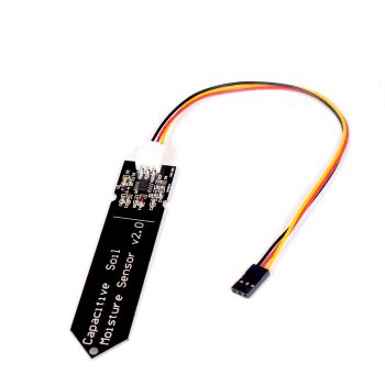
Capacitive Soil moisture sensor:
This is a good starting point as it measures a crucial factor for plant health. You can build one using readily available materials like electrodes and Arduino boards.
Additional Sensors:
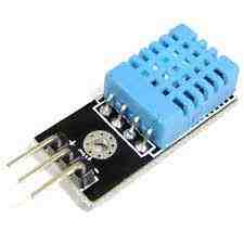
Temperature sensor: Measures soil temperature, influencing nutrient availability and plant growth.
pH sensor: Measures soil acidity, impacting nutrient uptake and microbia activity.
NPK sensors: Measures the amount of nutrients are in the soil content.
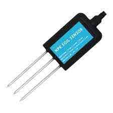
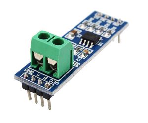
MAX845 module
Also with the NPK Sensor, I also need the MAX485 module to be able to control the npk sensor.
Organic matter sensor: Organic matter plays a vital role in soil health, improving water retention, aeration, and nutrient cycling. Measuring organic matter can give you an idea of the overall health and fertility of your soil.
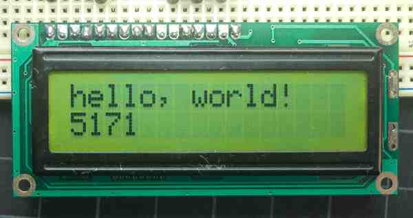
LED screen: Its is mainly present to display the data it has been able to fetch, such as the needs of the soil and the potential dangers it might be exposed too.
calibrate: A way to calibrate all the sensors at the right scale so that the measurings and suggestion can be accurate
Case: How the project looks from the outside
These are the sketch of how i want my final project to look like, I want my poject to be as compact as possible. I also want my project to be very simple to make so that it can be made in large amounts, not only that but it should also be give very accurate suggestions.
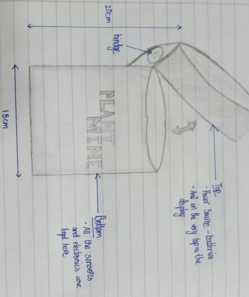
Dimensions
Dimeter: 15cm
Height: 20cm
What my final project should be
beginner friendly: Meaning it should be easy enough for almost anyone to use
accurate: It should give acuurate and effective suggestions for it to be reliable
cost effective: It should be really cheap and easy to make so that it is avaible everywhere
Portable: It should be small and conpact enough for people to carry and place it anywhere
Reusable: It should not be a one time use but be able to use again and again.
Power source
Btteries: Since I want to my project to be reusable, batteries would be the easiest and most efficient as they take up less space and also are replacable. With that if the battery dies, we can just replace it with another one.
Micro Contoller
ATtiny 3216 : Since my peoject requires a lot of sensors, it also needs alot of pin to receive all the out put form the sensor
Modelling 😀
In our student boot camp, We were introduced to the concept of the spirial devlopment! The spiral devlopment is a process where you create several variations of your project. The variations of your project should always become better and better, additionally you also gain valuable knowledge of your project. This is my very first stage of my spiral development and I was tasked with creating a cardboard model of my project. Through this I will be able to see all the flaws in my design which I would be able to improve on.
Now the grand reveal of my of my project that i have created 🤩

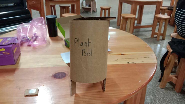
Its a bit underwhelming, but mind I say it most likely saved alot of time in the near future as I able to identify several mistakes with this one "spirial model" itself😋!
Flaws In my design 🤦
✓ Firstly I noticed that my design had a lot of fragile sensor that were protruding out of the bottom of my model. Not only did it make my model unstable, but I was also running high risk with the possibility that the sensor could break easilly. For that I think I should add a sort of scaffold that would run across its surface and would act as a framming around my design. The scaffold would be made so that it is just a bit longer than the sensor so that it would also act as support for the model to stand.
✓ Now the second flaw that i noticed in my design would be its size. I realised how my model trully is when I actually made the scale replica with the use of cardboard. I saw how small the sensors were and how I could make my design even more compact so that my design would be transportable and cheap. For this project almost no wastage would be tolerated 😤😤😤!
Well that was it fot this spirial. I cant wait to see all the changes that i might make in the future for my project and how it might look like then.
Circuit Board creation☕
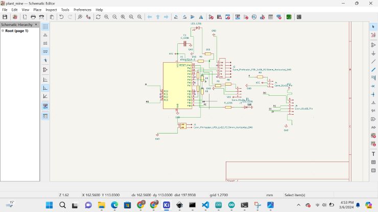
Now lets move on to creating the circuit board that I will be using to control all my sensor. Firstly let's begin with the schematics of the board.
With that out of the way I also edited in the PCB editor of kicad
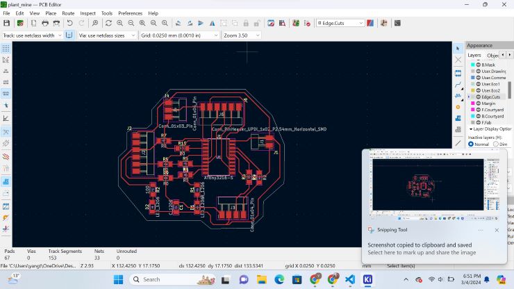
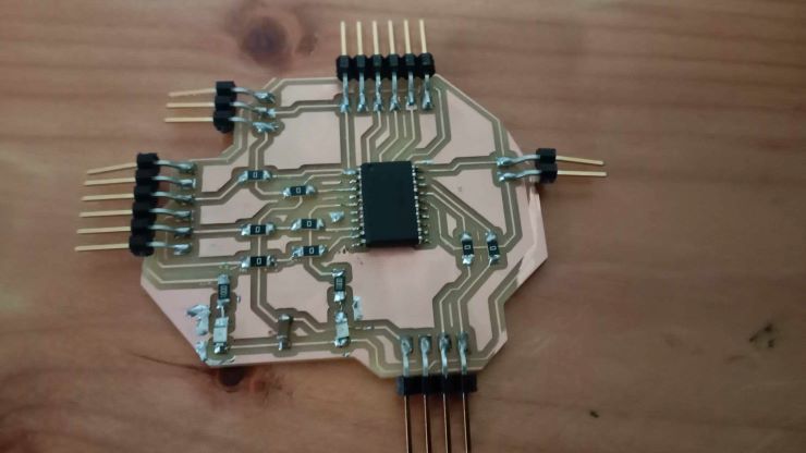
Now this is my frist circuit board that is ment for my final project, Ohh god let this work🗿.
Codes for my project 🥲
This is just a dev code for my final project and I just wanted to put this here as who knows this might just endup working in the near future.
#include <Wire.h>
        #include <LiquidCrystal_I2C.h>

        // Define sensor pins
        #define MOISTURE_SENSOR_PIN A0
        #define NPK_SENSOR_PIN A1

        // Define LCD display parameters
        #define LCD_ADDRESS 0x27
        #define LCD_COLUMNS 16
        #define LCD_ROWS 2

        // Create the LCD object
        LiquidCrystal_I2C lcd(LCD_ADDRESS, LCD_COLUMNS, LCD_ROWS);

        void setup() {
          // Begin I2C communication
          Wire.begin();

          // Initialize the LCD
          lcd.begin(LCD_COLUMNS, LCD_ROWS);

          // Clear the LCD
          lcd.clear();
        }

        void loop() {
          // Read moisture level
          int moistureLevel = analogRead(MOISTURE_SENSOR_PIN);

          // Read NPK level
          int npkLevel = analogRead(NPK_SENSOR_PIN);

          // Clear the LCD
          lcd.clear();

          // Print the moisture level
          lcd.setCursor(0, 0);
          lcd.print("Moisture: ");
          lcd.print(moistureLevel);

          // Print the NPK level
          lcd.setCursor(0, 1);
          lcd.print("NPK: ");
          lcd.print(npkLevel);

          // Wait a bit before the next reading
          delay(2000);
        }
This previous codes just give you the readings of the sensors. The code after this is to calibrate the sensors(It might be a bit different as their calibration and my calibration should be different.)
// After printing the NPK level
        if (moistureLevel < THRESHOLD_LOW_MOISTURE) {
          lcd.setCursor(0, 2);
          lcd.print("Add more water");
        } else if (moistureLevel > THRESHOLD_HIGH_MOISTURE) {
          lcd.setCursor(0, 2);
          lcd.print("Too much water");
        }

        if (npkLevel < THRESHOLD_LOW_NPK) {
          lcd.setCursor(0, 3);
          lcd.print("Add more fertilizer");
        }
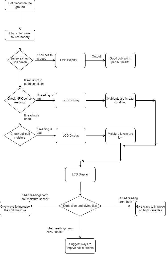
Flow chart😀
This a flow chart of how my project works. It also includes The output the bot will give
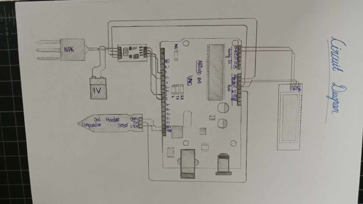
Circuit design for Sensor
This is a sketch of the circuit which includes all my sensors pluged onto an arduino board. The reason I did this Sketch was so that I will be able to indentify the Pinouts of each and every component that I will be using! This also provides me with a brief idea on how I am supposed to connect my sensor to the micro controller.