Week 11: Input devices❤!
Now lets get in to the world of sensors! For this week we have to use a sensor/input device to collect data. To do that we can choose from a wide variety of sensors to choose from! Though for this week I will only be using one sensor.
Professor Neil also spoke a lot about sensors as a form of input device. Speaking on ways of communication with the sensor and all the different types of sensor we might be using for this week.
Assignment
For this week we have to control a sensor using our board.
Group Assignment☀
Probe an input device(s)'s analog levels and digital signals
Document your work on the group work page and reflect on your individual page what you learned
For this week we had to use the Oscilloscope to measure the signals generated by both the ultrasonic sensor and the sound sensor.
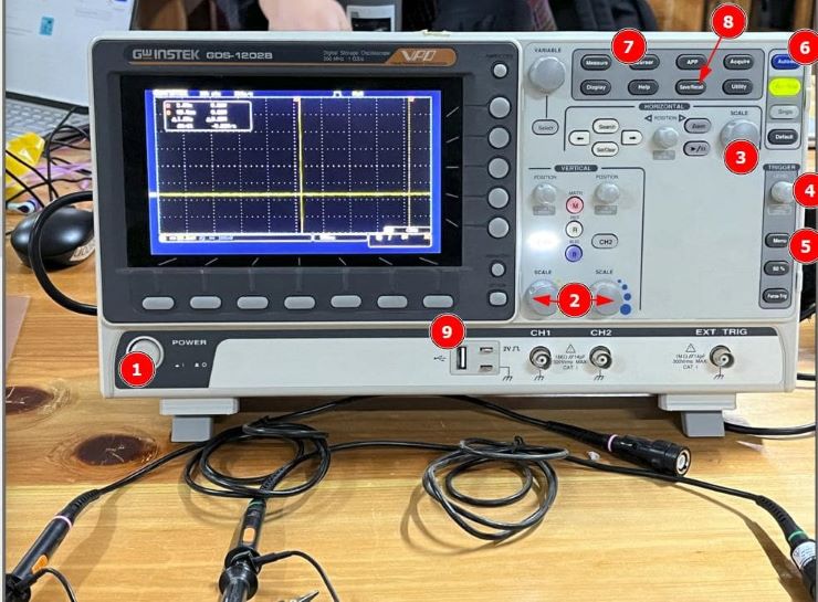
For the group assignment I used a micro controller and then connected them to input devices. The analog values that they gave off was then measured and then visualized through the use of the Oscilloscope.
The sound and ultrasonic sensors used the analog pins so we could simply use the analog read code for the group assignments to read its value and then display it onto the serial monitor. Then connect the analog pins to the probes of the Oscilloscope and then we are able to see more of how the data acts and gives us a visual representation of the data.
If you want to see how we did it, please go to our group documentation.
Reflection
This week was very fun as I was able to learn a lot of how sensors actually send data and how the electrical signals look like. I am learning at a pace like never before. I feel more and more knowledge is entering my small brain. I really like how the fab academy is constantly able to give me new lessons on both technology and then also give me crucial life lessons for the future.
DHT11 sensor!!!
Before I start with anything I first have to start a sort of mock test to see whether the code I am using is functional or not. Also! almost forgot to mention I will be using the DHT11 sensor as my primary input device.
The DHT sensor is a commonly used temperature and humidity sensor in the Arduino community. It comes in different models, such as the DHT11 and DHT22 (also known as AM2302). The sensor consists of a capacitive humidity sensor and a thermistor to measure temperature. It also includes an integrated circuit that performs analog-to-digital conversion and provides digital output for temperature and humidity readings.
Here's a brief overview of how the DHT sensor works:
Sensing Elements: The DHT sensor contains a humidity sensing element and a temperature sensing element. The humidity sensing element is a capacitive sensor that measures the relative humidity in the surrounding environment. The temperature sensing element is typically a thermistor, which changes its resistance based on temperature.
Digital Output: The DHT sensor provides digital output in the form of a serial data stream. The data stream includes the temperature and humidity readings, typically in a binary format.
Communication Protocol: The DHT sensor uses a proprietary single-wire communication protocol to transmit data. This protocol requires precise timing, which is handled by libraries like the DHTlib in the Arduino environment.
how does the single wire communication work
When MCU sends a start signal, DHT11 changes from the low-power-consumption mode to the running-mode, waiting for MCU completing the start signal. Once it is completed, DHT11 sends a response signal of 40-bit data that include the relative humidity and temperature information to MCU. Users can choose to collect (read) some data. Without the start signal from MCU, DHT11 will not give the response signal to MCU. Once data is collected, DHT11 will change to the lowpower-consumption mode until it receives a start signal from MCU again.
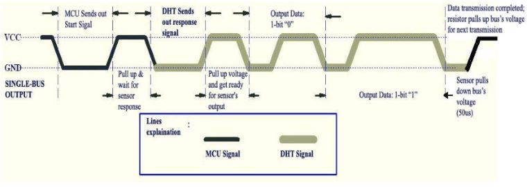
The above explanation is from the data sheet of the sensor. If you want to visit the data sheet, please visit the here --> datasheet
Setting up/ pin configuration😀
Now firstly for the mock test I will be using the arduino dev board to see whether all the components were working as planned.
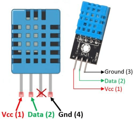
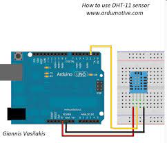
Also to use the arduino board we first have to connect it to the arduino. The orientation of the pins is like wise.
Power: Connect the VCC pin of the DHT sensor to the 5V pin of the Arduino board.
Ground: Connect the GND pin of the DHT sensor to the GND pin of the Arduino board.
Data: Connect the data pin of the DHT sensor to a digital pin on the Arduino board. Choose any available digital pin.
Programming
Now lets start with programming our dev board so that we can start using our sensor!
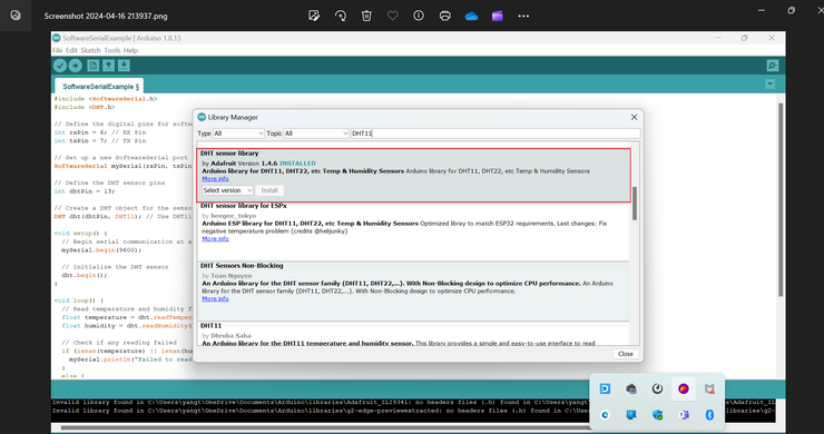
Firstly we have to open arduino IDE and then we have to download the required library so that we can start programming our DHT11 sensor.
This is the library that I installed so that I would be able to use the DHT sensor
With this library installed I started writing my code that I would use to use the DHT sensor!
After all that struggle this is how the DHT sensor looks.
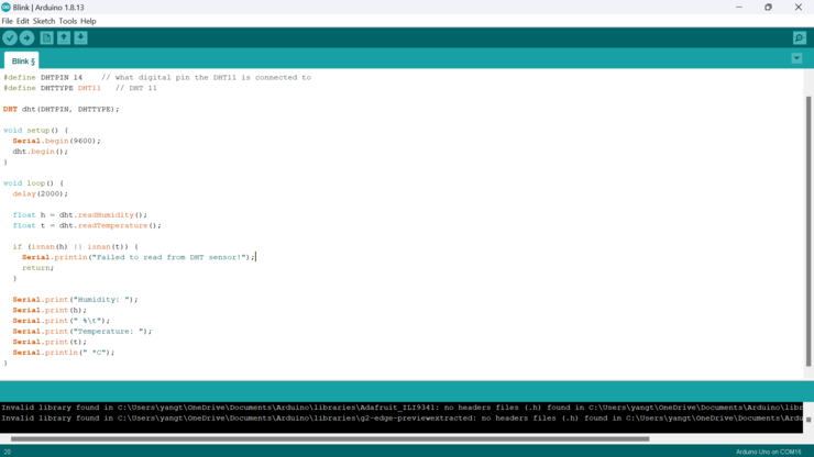
This is the code that I used to control the DHT sensor.
#include "DHT.h"

    #define DHTPIN 14    // what digital pin the DHT11 is connected to
    #define DHTTYPE DHT11   // DHT 11

    DHT dht(DHTPIN, DHTTYPE);

    void setup() {
    Serial.begin(9600);
    dht.begin();
    }

    void loop() {
    delay(2000);

    float h = dht.readHumidity();
    float t = dht.readTemperature();

    if (isnan(h) || isnan(t)) {
        Serial.println("Failed to read from DHT sensor!");
        return;
    }

    Serial.print("Humidity: ");
    Serial.print(h);
    Serial.print(" %\t");
    Serial.print("Temperature: ");
    Serial.print(t);
    Serial.println(" *C");
    }
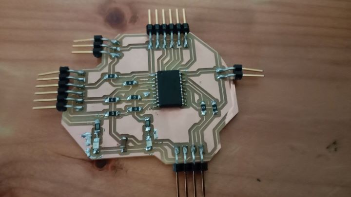
Attiny3216
Now lets start programming the DHT sensor using my final project board.
This board was made in this week here, for my electronic production week. --> electronic week
Firstly though I have to find another way to use the serial monitor as my attiny 3216 micro controller is programmed through UPDI and cannot open serial monitor like normal dev boards can.
To get around this my instructor(Mr Anith) Recommended using the software serial library through which you will be able to open up serial monitor through the use of a FTDI cable. Thank you very much for that tip sir.
To understand more about the software serial library and how it is used, I visited the Arduino Website.
After I though I was ready to use software serial, I started.
I wrote the code down and then I first set up my Jtag2UPDI programmer.
I needed a UPDI programmer and for that I decide to turn a arduino board into my updi programmer. Visit this documentation right here.
If not visit my documentation page on week 8. It has all the necessary steps that would help you turn your arduino into a UPDI programmer.
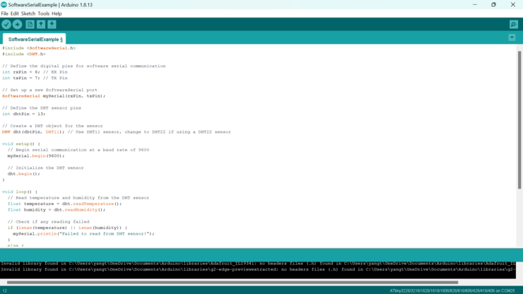
This is the code that I hope to upload onto my micro board.
#include <SoftwareSerial.h>
    #include <DHT.h>

    // Define the digital pins for software serial communication
    int rxPin = 6; // RX Pin
    int txPin = 7; // TX Pin

    // Set up a new SoftwareSerial port
    SoftwareSerial mySerial(rxPin, txPin);

    // Define the DHT sensor pins
    int dhtPin = 13;

    // Create a DHT object for the sensor
    DHT dht(dhtPin, DHT11); // Use DHT11 sensor, change to DHT22 if using a DHT22 sensor

    void setup() {
    // Begin serial communication at a baud rate of 9600
    mySerial.begin(9600);

    // Initialize the DHT sensor
    dht.begin();
    }

    void loop() {
    // Read temperature and humidity from the DHT sensor
    float temperature = dht.readTemperature();
    float humidity = dht.readHumidity();

    // Check if any reading failed
    if (isnan(temperature) || isnan(humidity)) {
        mySerial.println("Failed to read from DHT sensor!");
    }
    else {
        // Print temperature and humidity values
        mySerial.print("Temperature: ");
        mySerial.print(temperature);
        mySerial.print(" °C\t");
        mySerial.print("Humidity: ");
        mySerial.print(humidity);
        mySerial.println(" %");
    }

    delay(2000); // Wait for 2 seconds before taking the next reading
    }
In this code I also had to define the RX and the TX pins as they are required for the software serial. I also had to add a command that initializes the software serial class into an object. Additionally I also had to change all the "Serial.print" commands to "mySerial.Print" so that it calls the software serial class.
The above code first initializes the software serial to establish a serial communication. Then I also included the DHT Library so that I can get accurate readings from the DHT sensor. After initializing a variable for the DHT sensor pin and then the for the rx and tx pins. I simply used the DHT library to get the readings. I also wrote a code to give me a message if the reading failed.
Now with all of done, we can finally start with controlling our sensor. 💀 It didn't work. For some reason the serial monitor just isn't responding to the signals it receives from the micro controller.
Rapid Debugging!😤
Now that I have encountered a problem, I must fix it as soon as possible so that I can continue on with my work!.
Firstly I tried using the multimeter and then checked all the possible places where there could have been a short to see if that could be the problem. After that I checked if all the signal where good and able to transfer data smoothly through them.
Although even after several checks and hours of debugging I just wasn't able to find the problem within the board.
I even check if my code was the problem, but it wasn't that either as when I uploaded the code onto the arduino, it worked with out a flaw😵. I even asked all my friends if they could find the problem, but even they weren't able to find the problem.
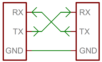
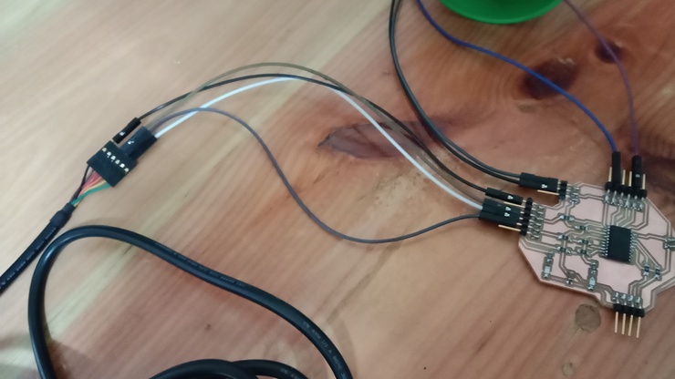
After a while I checked if all my connections were correct or not, while I was in the midst of doing that my instructor Mr Anith showed up and suspected the connections of my FTDI. After closer inspection, he was right! my FTDI connection pin headers were exactly identical to the FTDI cable. It may not seem like a problem, but the thing is that if the pin header is exactly identical to the cable, It means that the RX and TX pins are also connected to the RX and TX of the micro controller.
For serial communication the RX of the micro controller has to be connected to the TX of the cable and vice versa.
After I fixed the problem by connecting the RX and TX properly, I send a demo code that would send "hello world" through the software serial to see if the serial monitor was working properly.
#include <SoftwareSerial.h>

    SoftwareSerial mySerial(6, 7); // RX, TX

    void setup() {
    // Open serial communications and wait for port to open:

    Serial.println("Goodnight moon!");

    // set the data rate for the SoftwareSerial port
    mySerial.begin(4800);
    mySerial.println("Hello, world?");
    }

    void loop() { // run over and over
    if (mySerial.available()) {
        Serial.write(mySerial.read());
    }
    if (Serial.available()) {
        mySerial.write(Serial.read());
    }
    }
The result!
For this code I establish a serial communication between my laptop and then my board by first. I created an object known as mySerial which held the values of the two pins which were going to be the rx and tx pins for my softwareSerial. After I established the serial communication I sent a serial message. Additionally I started a serial monitor on a buad rate of 4800. Then I printed the message hello world.
Now that I know what caused the problem, I do feel a bit dumb🤡, But I am happy that this incident took place as I was able to learn a lot of different things through this error and also was able to get to know my board a lot more than I used to. Therefore I must also thank myself for making that mistake as it did help me in the long run.
DHT Sensor!!!
Now with all things set and ready lets start with controlling our DHT using our micro controller.
Firstly the pin configuration of the DHT with my micro controller.
VCC - The VCC pin is connected to one of the many VCC pins on my micro controller.
Signal pin - The signal pin is connected to a digital pin on my micro controller.
GND - The ground pin is also connected to one of my several ground pins.
I used the same code that I showed in the previously. Now here is the final result of all the work I had to did.
Ultra Sonic sensor
Now that I have already used the DHT sensor, I will be using the ultra sonic sensor as well.
An ultrasonic sensor is a device that uses sound waves at frequencies beyond human hearing to detect objects and measure distances. It works based on the principle of sound wave reflection.
Ultrasonic sensors typically consist of a transmitter(Trig) and a receiver(Echo). The transmitter emits ultrasonic waves, which are high-frequency sound waves that travel through the air. When these sound waves encounter an object in their path, they reflect back towards the sensor.
The receiver in the sensor detects the reflected sound waves. By measuring the time it takes for the waves to travel to the object and back, the sensor can calculate the distance between itself and the object. This is possible because the speed of sound in air is relatively constant, so the time taken for the sound waves to travel a known distance can be used to determine the distance to the object.
The sensor communicates with the arduino by initializing serial communication and sets up the trigger and echo pins. It then triggers the sensor, measures the duration of the echo pulse, and calculates the distance based on the speed of sound. The distance measurement is displayed on the Serial Monitor.
The above information is from this website here. --> SITE
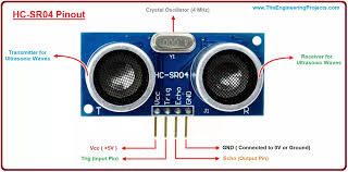
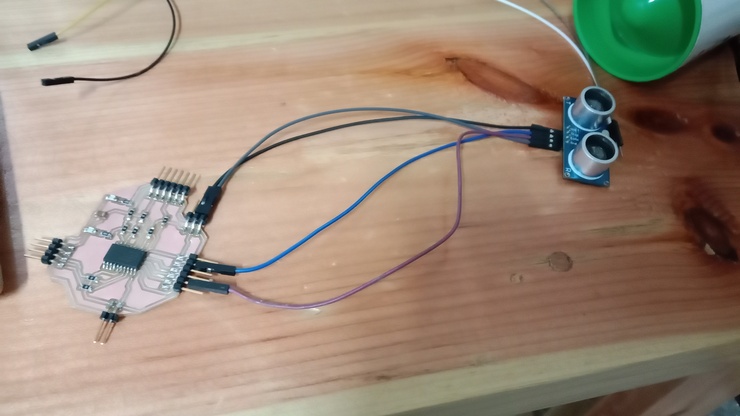
Pin configuration
the ultra sonic sensor has 4 pins
VCC: This pin is used to connect the sensor to the power supply. It should be connected to the 5V pin power source VCC.
Trig: The Trig pin is the trigger pin of the ultrasonic sensor. It is used to send a trigger signal to the sensor for initiating the ultrasonic pulse. This pin needs to be connected to a digital pin .
Echo: The Echo pin is the receiver pin of the ultrasonic sensor. It receives the echo signal when the ultrasonic pulse reflects back from an object. The time taken for the echo signal to return is used to calculate the distance to the object. The Echo pin also needs to be connected to a digital pin.
GND: The GND pin is the ground pin of the ultrasonic sensor. It should be connected to the ground (GND).
Setting Up
Now start setting up the ultrasonic sensor to my micro controller and also start with writing the code for the micro controller to be able to control the ultrasonic sensor and also be able to retell the collected data on to the serial monitor.
Before doing anything lets open up arduino IDE and start writing the code so that we are able to control the ultra sonic sensor.
The ultra sonic sensor doesn't require any additional library, therefore we can directly get into writing our code. This is the code I used for my ultra sonic sensor.
#include <SoftwareSerial.h>

    // Define the ultrasonic sensor pins
    const int trigPin = 10; // Trig pin connected to digital pin 2
    const int echoPin = 13; // Echo pin connected to digital pin 3

    SoftwareSerial mySerial(6, 7); // SoftwareSerial object with RX and TX pins

    void setup() {
    Serial.begin(19200); // Initialize the hardware serial communication
    mySerial.begin(9600); // Initialize the software serial communication

    pinMode(trigPin, OUTPUT); // Set trig pin as an output
    pinMode(echoPin, INPUT); // Set echo pin as an input
    }

    void loop() {
    // Send a trigger signal to the ultrasonic sensor
    digitalWrite(trigPin, LOW);
    delayMicroseconds(2);
    digitalWrite(trigPin, HIGH);
    delayMicroseconds(10);
    digitalWrite(trigPin, LOW);

    // Measure the duration of the echo signal
    long duration = pulseIn(echoPin, HIGH);

    // Calculate the distance based on the speed of sound
    float distance = duration * 0.034 / 2;

    // Print the distance to the serial monitor
    Serial.print("Distance: ");
    Serial.print(distance);
    Serial.println(" cm");

    // Send the distance to the software serial
    mySerial.print("Distance: ");
    mySerial.print(distance);
    mySerial.println(" cm");

    delay(1000); // Wait for 1 second before the next measurement
    }
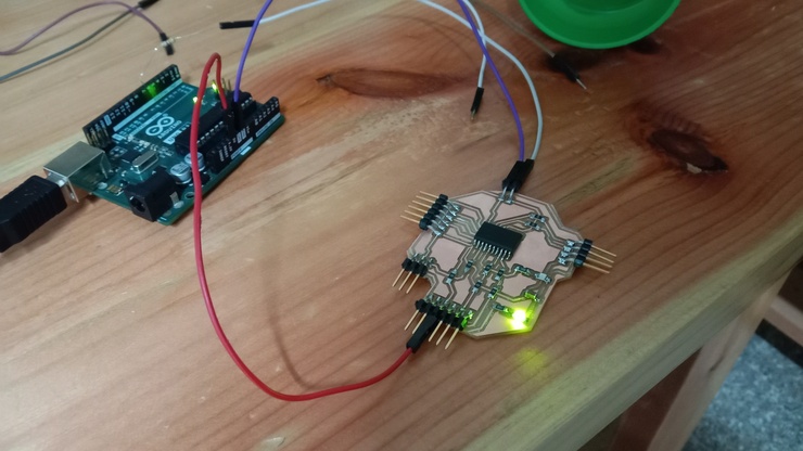
Now lets set up all the components and my board so that I can program my board.
The above code is actually really simple. I first as before included the software serial library and then also Initialized the pins for both the echo and trig pins. (echo = input and trig = output) After that The loop() function is where the main code execution happens. It starts by sending a trigger signal to the ultrasonic sensor by briefly setting the trigPin to LOW, then HIGH, and then back to LOW. This triggers the sensor to send out ultrasonic waves. Next, the duration of the echo signal is measured using the pulseIn() function. This function calculates the time it takes for the ultrasonic waves to bounce back to the sensor. Now finally the value is displayed onto the serial monitor with also a "distance" in front of the value and then "cm" behind the value
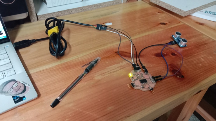
Hero Video/Shot
this is the board I used and then the result of it working
I made this board during my electronics production week. Here is the link to it if you want to visit. --> Week 8 - electronic week