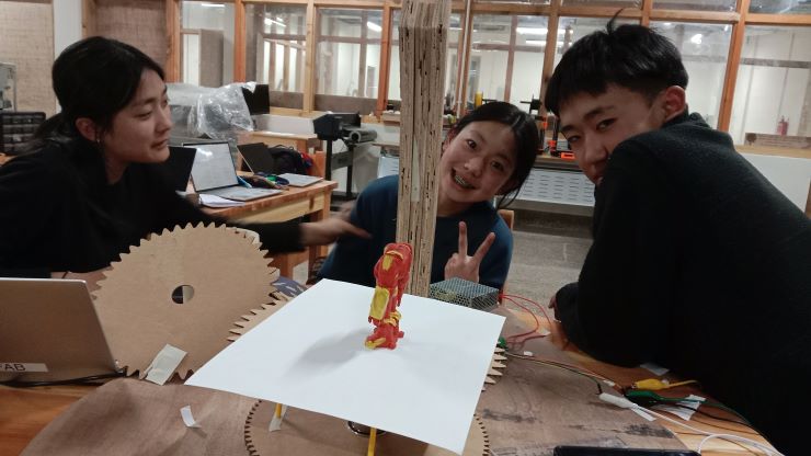
Week 10🥶!
This week we had to create a working and functional machine that we could use to in our lab. It was a really fun but I must say, it was the most exhausting week of them all! With the huge workload of this week and pair that with fact that I had my exam to do as well! Yeah honestly I really had to work my head off for this week. I really hope that the machine that we created doesnt disapoint.
Professor Neils lecture🧐
For this week professor neil explained about all the ways through which you would be able to create a machine. He explaned the use of motors, components and materials. Focusing a lot on how different materials have their own pro's and cons. With also explaining the use of multiple different components such as the ball bearing or nuts and bolts. Emphasising a lot on how the correct use of components is always important to know.
Group Assignment
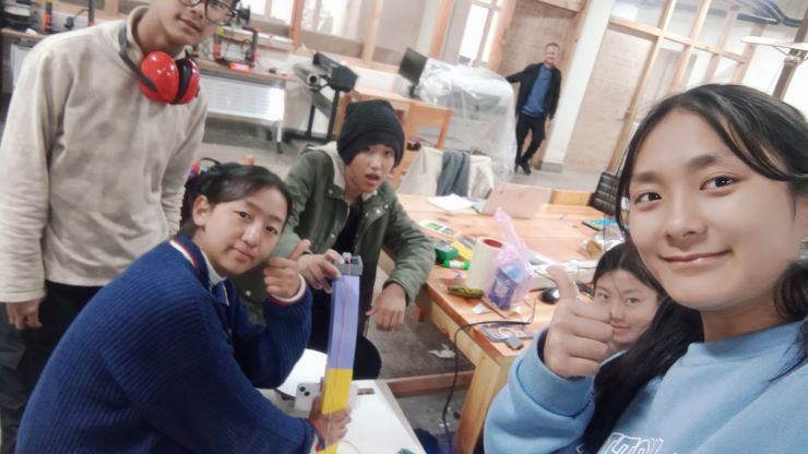
This weeks group assignment it self was about how we created our machine. For this group assignment I was a part of the designing team and also help them in the a bit of electronics
Machine🤖!!!
Alright lets now get into the machine that me and my peers intend to create!
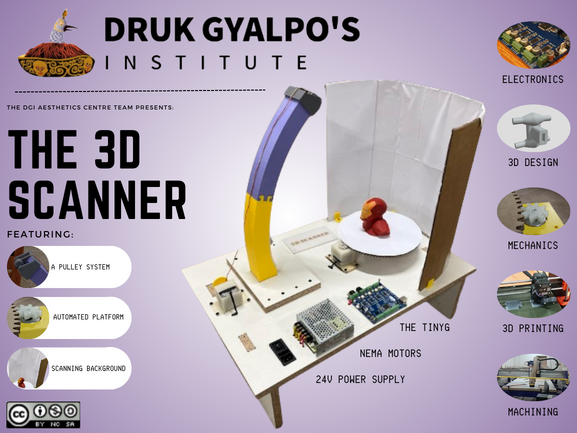
The machine that we have decide to create was an automatic 3D scanner that would be able to scan objects that have been placed in it! We decided upon creating this as in our lab, the DGI Astheic Center, we have a lot of different machine that we use. Though there is one machine that our lab doesn't own. The very machine that our lab doesn't is a 3D scanner. We decided to make the 3D scanner as our machine for this week, not only to have it as an addition to our lab, but also to thank it for all the experinces we had with it 🥰!
This is the poster of the machine we created
Reflection
as the designer of this group it was a very tough job to create the designs for this machine of ours. I had to spend a lot of time designing, fixing or scraping the design and starting all over again. But that has taught me many significant lessons such as the importance of the dedicationa and rigor while working on somthing. If I count the amount of times I had to scrape my design and start all over again, it might round up to around the twentys. I alot of my designs just didnt work the first time I did it and it was really frustrating! but I didnt give up and then persaveried through.
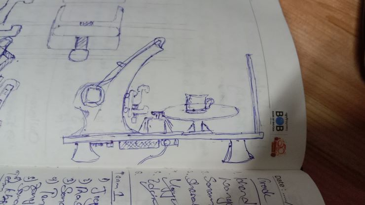
Now lets get into how we are actually going to create our machine. We first envisioned a design like this one.
Fusion360
Fusion360 is a comprehensive CAD/CAM/CAE software developed by Autodesk, suitable for mechanical design and engineering projects. This is the software we’ll be using for most of the 3D designing.
Getting Started
If you don't already have an account, you can sign up at this link:
(Once your account is set up, click on "Create" and then select the appropriate workspace for your project.)
If you are unable to download the software (like me at first), what I did was use the browser version.
(Just press LAUNCH and get started)
So we started off by creating the arm, and creating a mechanism for the scanner to move on the z-axis.
Research
Before the actual designing, we did some research on different 3D scanners that were made in the past, and we found quite a few interesting ones. However, one that really stuck out (and one that we referred to religiously) was by Mr. Quentin Bolsée 🙏
After some trial and error, we created this curve, with a slot for our scanner carrier.
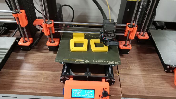
At first we were planning on creating the arm using the CNC machine but we changed plans and then decided to just 3D print the arm in parts for it to be smoother
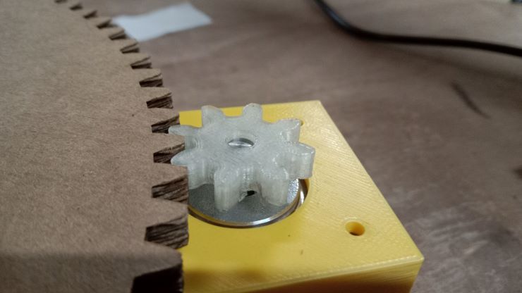
Pulley Head
We decided to use a pulley system to move our scanner, so I started working on that using the arm, and a 16mm bearing as a reference.
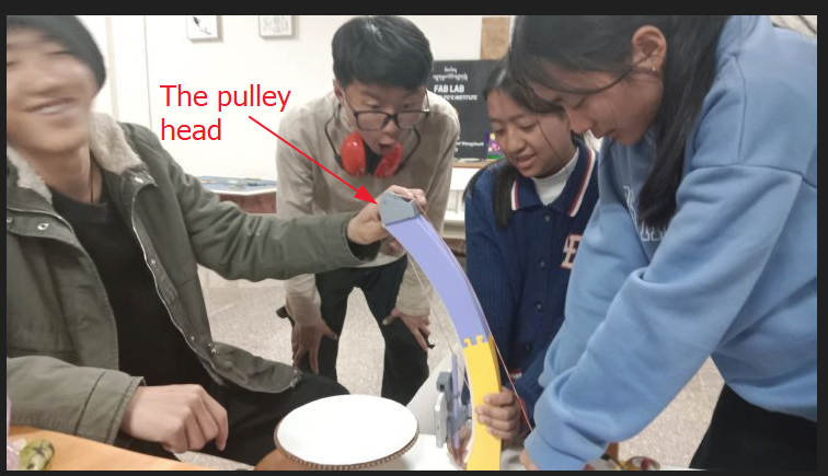
The pully head is there on the machine to reduce tension in the wire. In the middle of the header there are bearings as well.
Cart
In the meanwhile, Thinley fabricated the cart that would move up and down the arm, and consequently move the scanner too.
The protrusions are for 16mm bearings, and an included slot to attach to the scanner. The four protrusions had bearings connected to them so that the cart could move up and down. Next in the center there is this slot for the phone holder that I will design later.
Electronics
Damzang and Ngawang were involved in the designing part of this week.
Programming
For the programming part of the machine building, we decided to take over. We tried to program the DC stepper motor to begin with and for this we took reference from this site
These are the steps we followed to program the stepper motor.
1. Connecting Power
First, we verified and double-checked the correct wiring of our power input (black for ground, red or yellow for +24 volts).
Then we used a DC power supply between 12 and 30 volts capable of providing 4 to 15 amps.
After that we turned on the power supply and checked for correct voltage and polarity before connecting it to TinyG.
2. Setting up Universal Gcode Sender
Now, regarding the software, we downloaded and installed Universal Gcode Sender, a terminal emulator through this site
Then go to the downloaded folder and then open this file
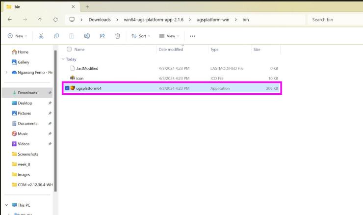
We selected the port
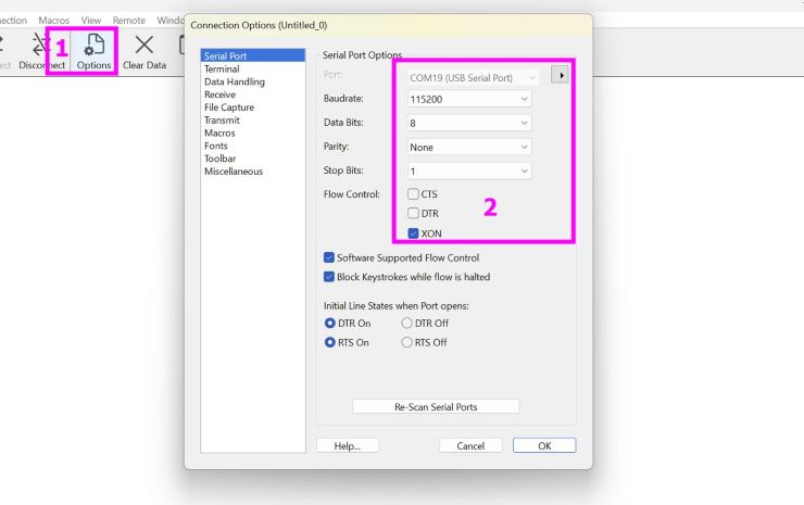
And connected to TinyG.
The content inside the green box indicates a successful connection.
Then we identified the coil pairs of our stepper motor using a volt meter.
After that, connected one pair of wires to the A1/A2 terminals and the other pair to the B1/B2 terminals on TinyG's motor outputs.
4. Setting Motor Current
Then using the trimpots near each axis, we adjusted the motor current.
We started with the current at zero and gradually increase it until the motor moved smoothly without stalling or running too hot.
Note: Avoid overdriving the motors, which can lead to overheating and damage.
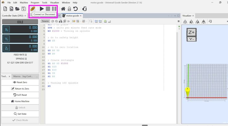
5. Test Drive
Once everything is connected and configured, test drive your stepper motor by sending movement commands through TinyG.
Check for smooth operation, correct direction, and appropriate speed.
For the test drive, we tried with the code that was given in the reference documentation.
We uploaded this code g1 f400 x100
In the above G-Code,
G1: This is a standard G-code command that instructs the machine to move in a straight line from its current position to a specified point at a specified feed rate.F400: This part of the command sets the feed rate or the speed at which the machine should move. The value 400 indicates a feed rate of 400 units per minute. This determines how fast the motor will spin.X100: This part of the command specifies the target position along the X-axis where the machine should move to. In this case, it's instructing the machine to move to the X-coordinate of 100 units.
It worked!!
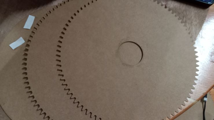
Next we tried it with a gear that will spin another gear!
For our scanning machine, we are trying to control 2 motors in which the first motor will be used to rotate the platform and the second second motor which will be kept side-down to move the scanning platform of the object vertically.
To control the 2 motors we tried several relevant codes which obviously didn't work in the first iteration but after several tries, the following code worked!!
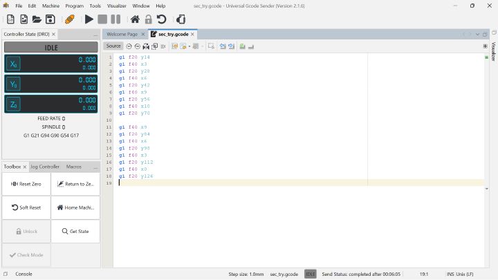
To see how this code worked, see our video for our 3D scanner.
Assembly
Lets now see how we assembled our machine.
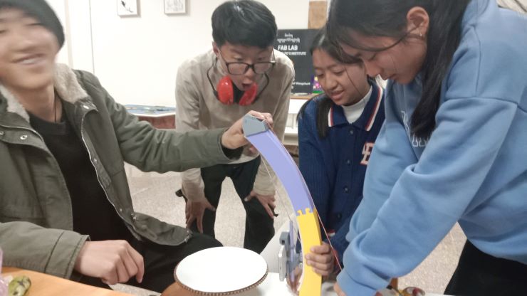
Lets make our gears and adjust them in place.
Now the arm!
The wooden arm that we printed didnt come out that good so we decied to 3D print the arm so that it can be smoother.
Now we started importing all the designs together.
My Work😄!!!
Now lets get into all the work that I did to contribute to the group project.
Firstly lets get into all the roles that I had taken in this week.
Manufacturer - I was given the task to cut or print all the designs that I or my friends give or sent me. I was given this role as my friends appointed me as the most experinced with using all the machines in the fab lab.
Designer - I also was given the task to 3D design some of the designs that are a part of the overall machine.
With that let me jsut show some of the things I contributed to and some of the work I did.
Work!
To show what I did for part of this assignment let me show you some of my contributions for this week.
Firstly let me show my contribution for assignment using the CNC.
Using the CNC we created the base of our machine. We decided to use Ngawang Pemo Drukps table that she created during her computer controlled machining week. We decided to use her table as was it not only simple and short, it was also provided just enough space for our entire project.
Now let me show you some of my designs as well.
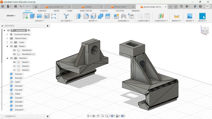
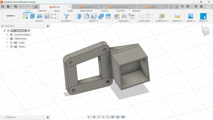
This is the phone case holder that I designed for the project. It was ment to be able to change according to the size of the phone. I thought of making that possible through the use of a pole that would have a thread that would be running through the hole that you can see in the picture there. Through the use of the pole thread,(The thread is somthing that I didnt create, it was somthing that was created by another member therefore I didnt include it in my design!) I was able to make it ajustable. When you spin the thread pole one of the part of the phone holder will either close up or open up. Also we took the width of the the iphone 13 which was the phone with the greatest width from all our other phones. For the adjustable phone case holder, I just had this design in mind but it took a lot of changes and updates to make it work. This is the 13 version of the of redesigning and then the 3rd itteration printing.
Lastly a lot of the print was also done by me.
The above design is that of the motor shaft. Our original vision of the enitre scanner was for it to have a sort of mechanism that allows it to go up and down the arm on its own. Somthing that is similar to what Quentin did.(all of us were so shocked seeing quentins camra moving on it own and really wanted to replicate it but couldn't 😄)
The design I created had two flaws. On one hand it was way to heavy as when I added in the motor, the motor wasn't even to pick it self up! Also when the mechanism moved up the motor some times wasnt making contact with the arm to climb up.
Reflection 02
this is the second reflection to this week and this is ment to convey whether the entire design work the way I planed for it to work or not. AND the answered to that question is a big NO! Almost nothing of the original plan remained when we had comlpeted our design. We first envisioned our design to be with the arm of the machine milled using the cnc and then have a moter track in there. After that stracp the phone/ scanner carrier to a shaft which will have a motor which will use the tracks on the arm to to climb up and then down. This was the original plan to our machine. But we also had to make a lot of change since there were a lot of flaws in that first envision.
- 3D printed arm:we created this 3D printed arm as the cnc milled arm provided way to many problems such as it being to thick due to the thickness of the wood(3 pieces being stacked on each other) and also it was't smooth and very refined.
- Motor Shaft: The motor shaft idea was way to heavy, quite literary! It was so heavy that the motor itself wasn't able to lift itself up.
- phone holder:The phone holder at first was only ment to fit a specific type of phone, but after the sugegstion of our instructor we decided to change it to an adjustable one.
With the flaws pointed out we directly moved on to creating our new design. We instead of using a motor shaft travel up and down, decided to ue the pully machanisum to move the machinium. After the all the work I just had to tidy up our work and make it all compact and all the wire have their own place for a good system integration.
Lastly I would like to thank all the people who helped us in this assignments.
Firstly we have our instructor, anith Ghally. His guidance was a really important factor to us being able to finish our assignment.
Also big thanks to quentin and his beautiful documentation.