Group assignment:
Complete your lab's safety training
Test runout, alignment, fixturing, speeds, feeds, materials and toolpaths for your machine
Document your work to the group work page and reflect on your individual page what you learned
Individual assignments
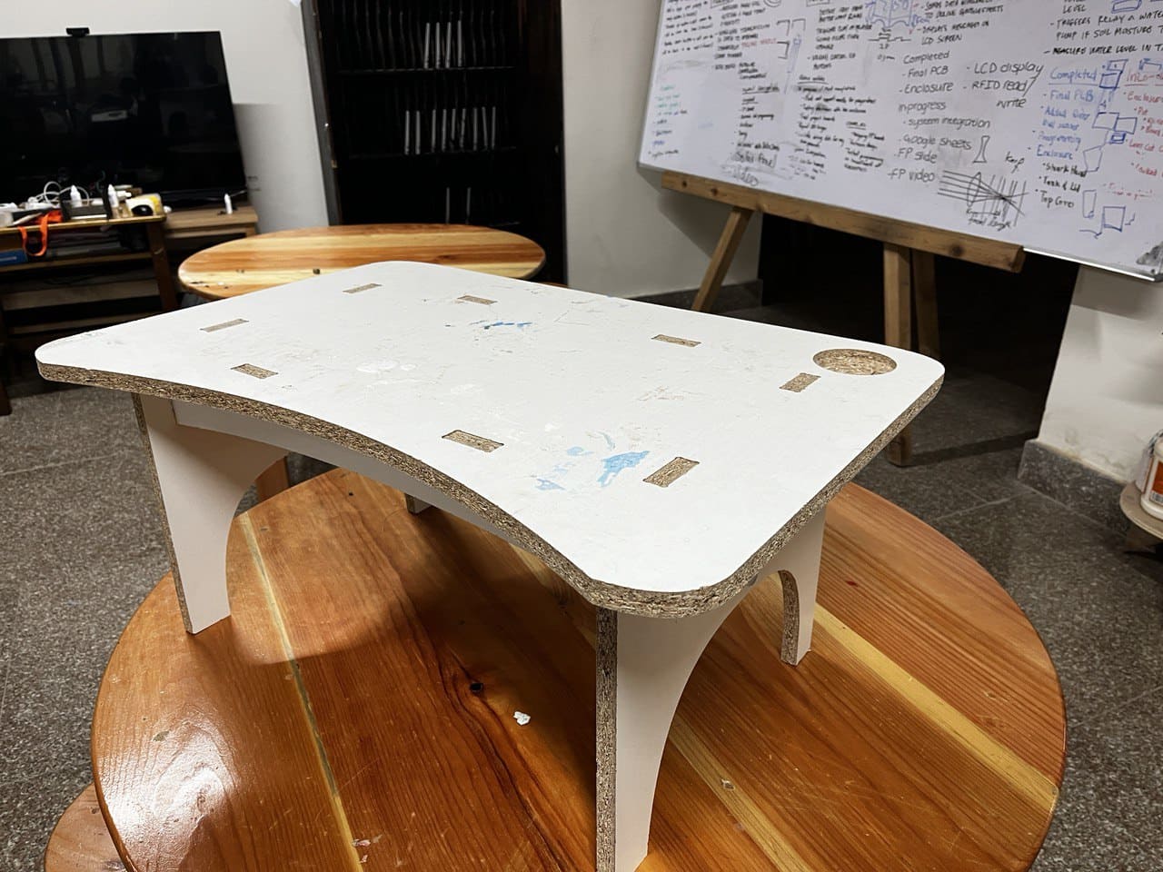
Make (design+mill+assemble) something big
Demonstrate 2D design development for CNC milling production
Describe workflows for CNC milling production
Linked to the group assignment page
Documented how you designed your object (something big)
Documented how you made your CAM-toolpath
Documented how you made something BIG (setting up the machine, using fixings, testing joints, adjusting feeds and speeds, depth of cut etc.)
Described problems and how you fixed them
Included your design files and 'hero shot' of your final product
Introduction:
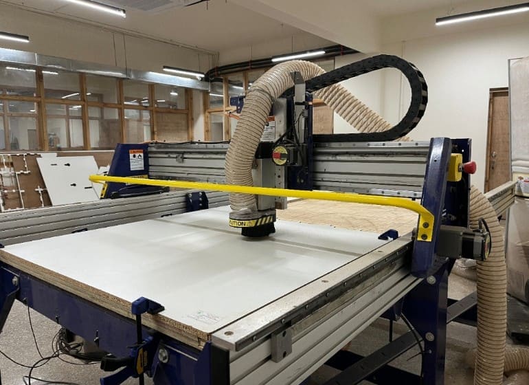
ShopBot PRS Standard CNC - Specifications:
Safety Rules:
Modeling and Cutting:
Conclusion:
Here is our complete group assignment
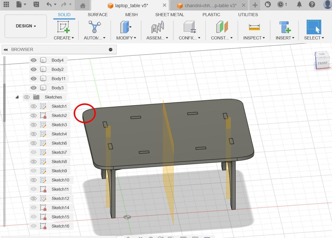
For the design, I decided to make a bed table for studying. I wanted to make a nice design, so I searched up on the fab academy site and found a design of a laptop table that Chandni Chhabra made.
Then I uploaded her file in fusion 360 and took reference from it to make my own design.
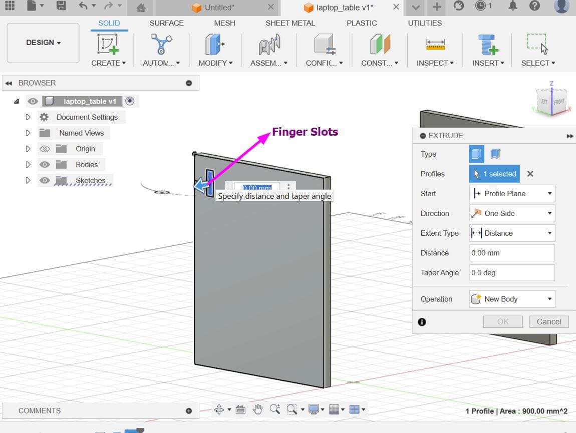
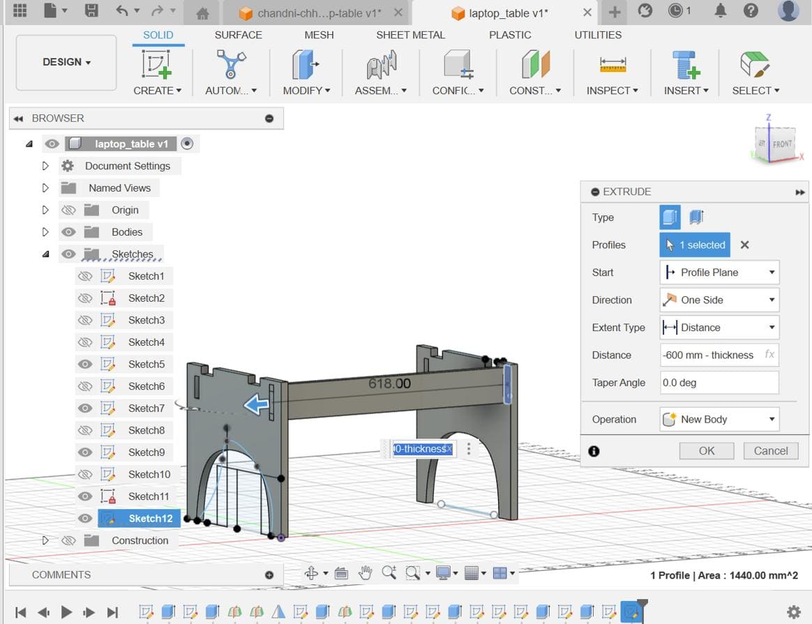
First I made a sketch of the table legs and extruded them. Then I added finger slots which was 5 by 1.8 cm and
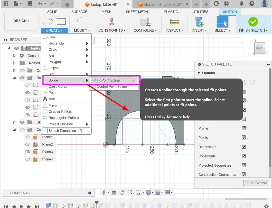
extruded it all the way through the other leg. Then I created a spline sketch on the leg to make a curve hole between the now separated legs.
After that, I created rectangle sketches in the areas that weren't the finger slot areas and extruded them by
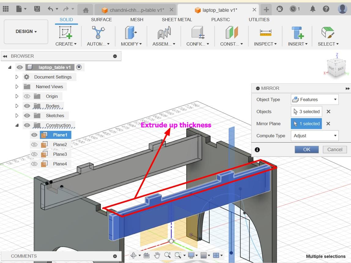
-thickness and mirrored it on the other leg. And then made a side sketch for my table support and
extruded it all the way to the other leg and mirrored it again on the other side.
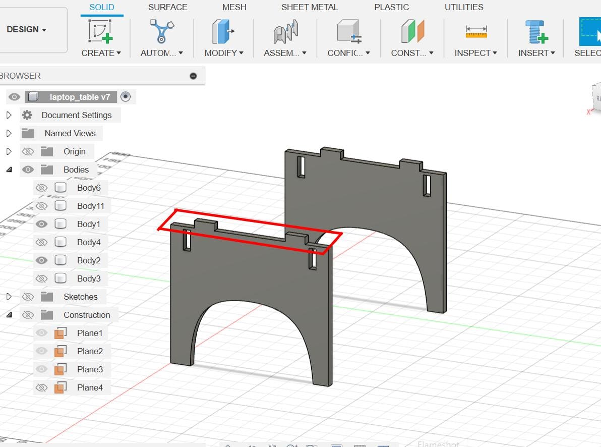
Then I again made finger slots on the support and mirrored them. I modified the support by creating a spline sketch on it and cutting it. I mirrored this on the other leg as well.
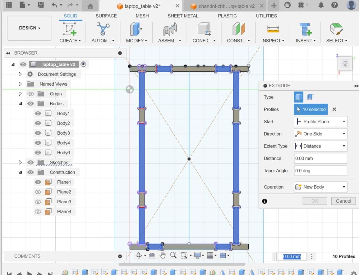
Then I again created rectangle sketches in the areas that weren't the finger slot
areas including the rectangular area between the legs and supports
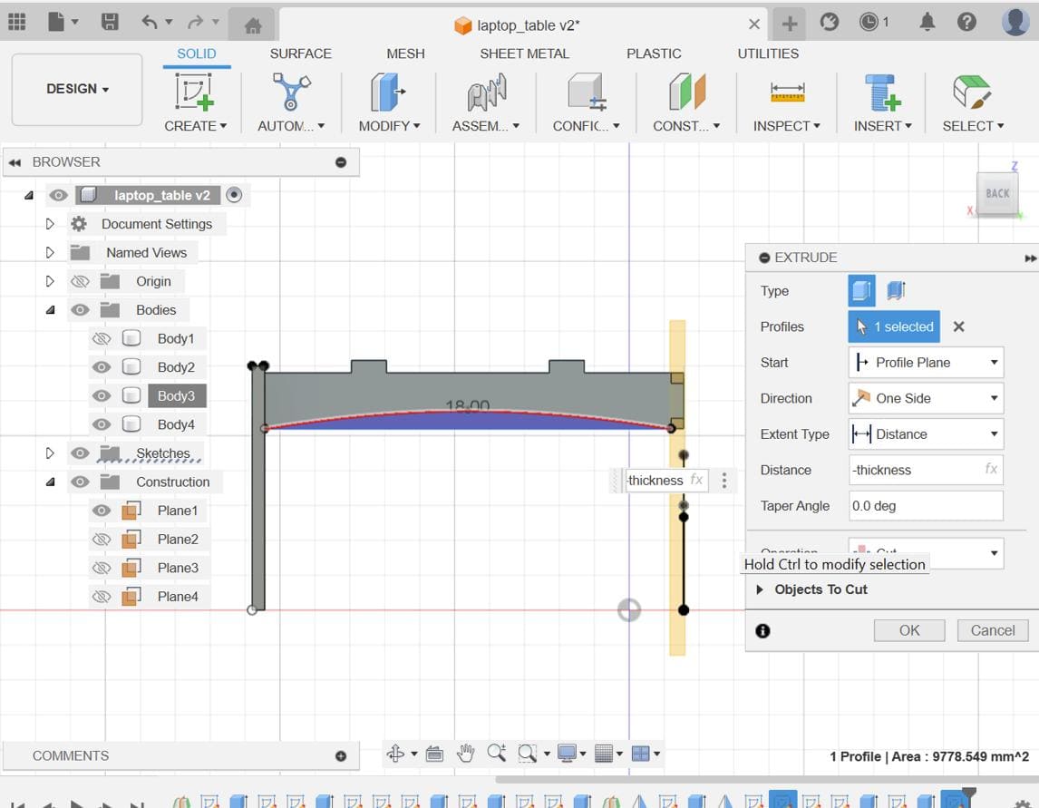
and extruded them by -thicknessAfter that I created side sketches to extrude the table to my desired length.
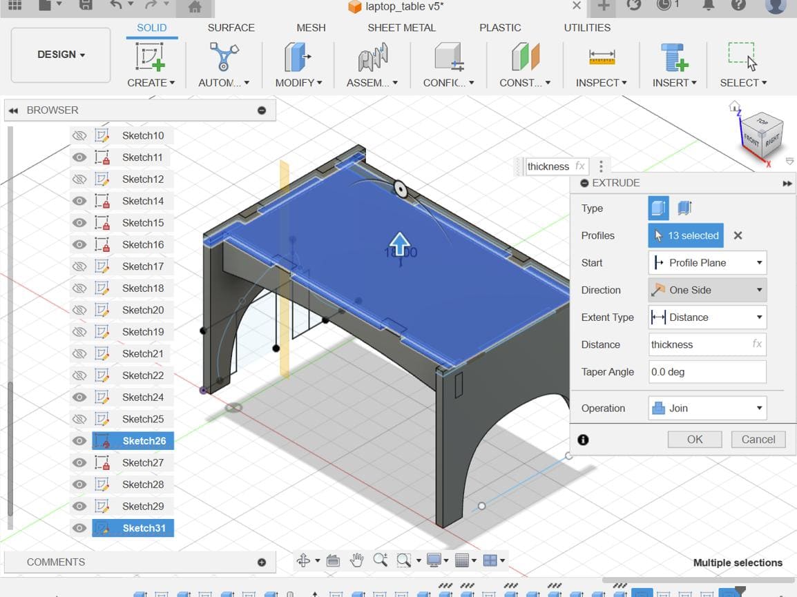
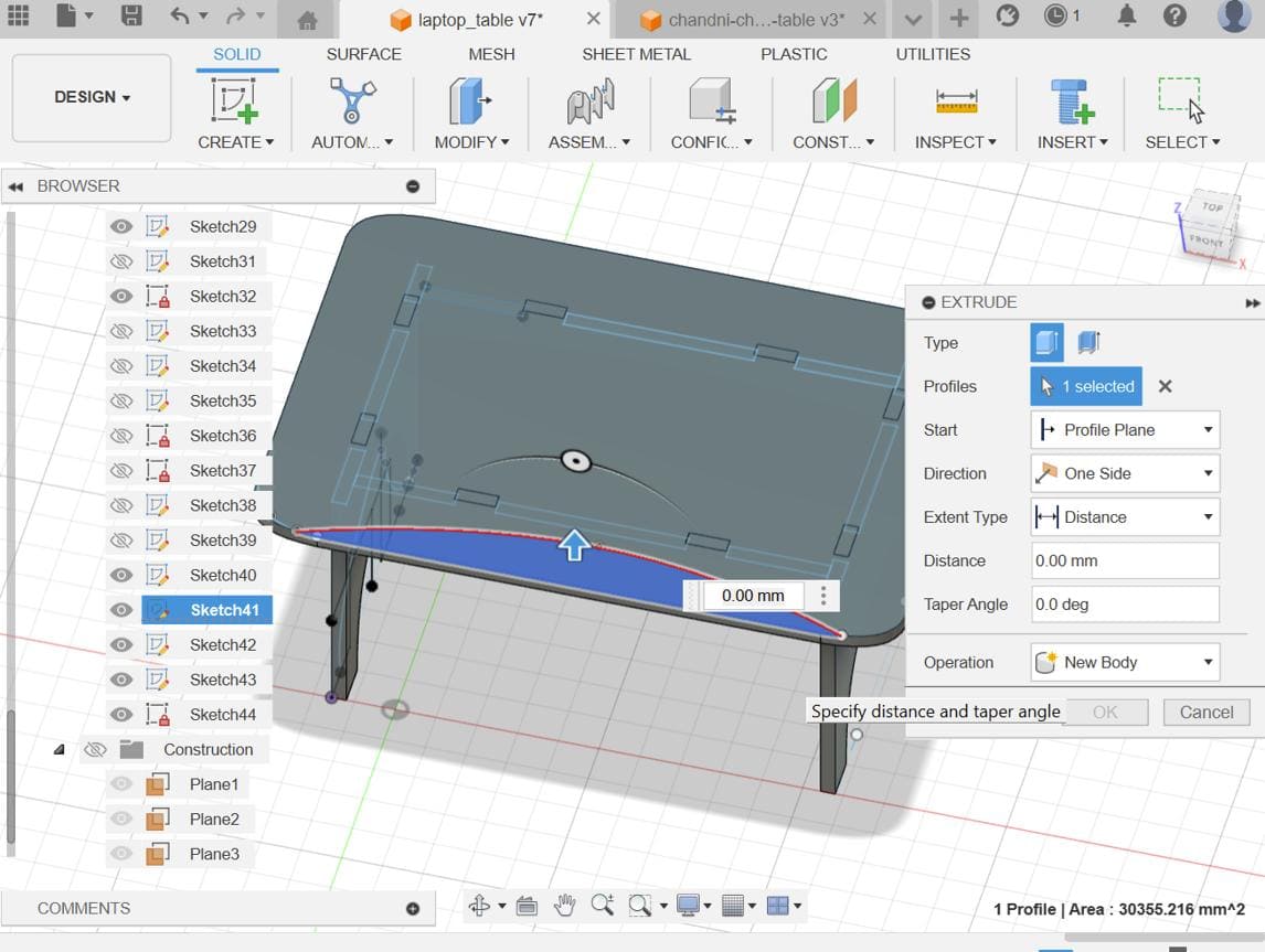
To modify the table top, I again created a spline sketch on one of the corners, cut it and mirrored it on all corners of the table. Again to modify the table top, I created a spline sketch on the side and extruded it for comfortability.
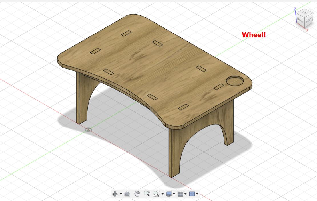
Lastly I added a slot for my bottle and cut it thickness/2. Here is the final result!!!!!!
Dogbone fillets are used to overcut into a corner when the application of the part you are making needs to fit tightly with another.
Here, you can see a short gif that shows the function of dogbone fillets
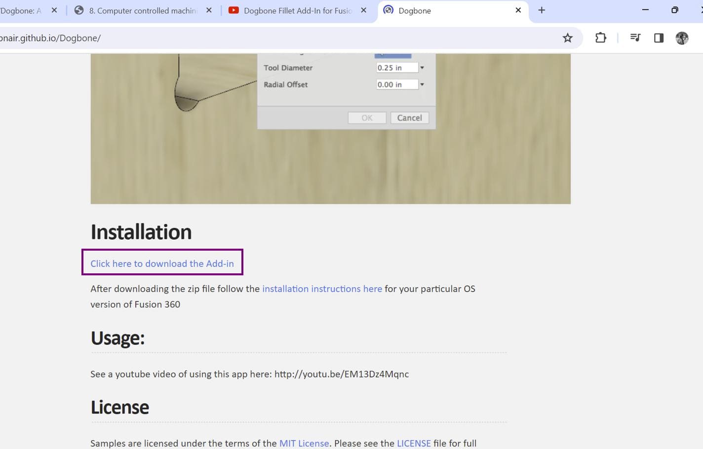
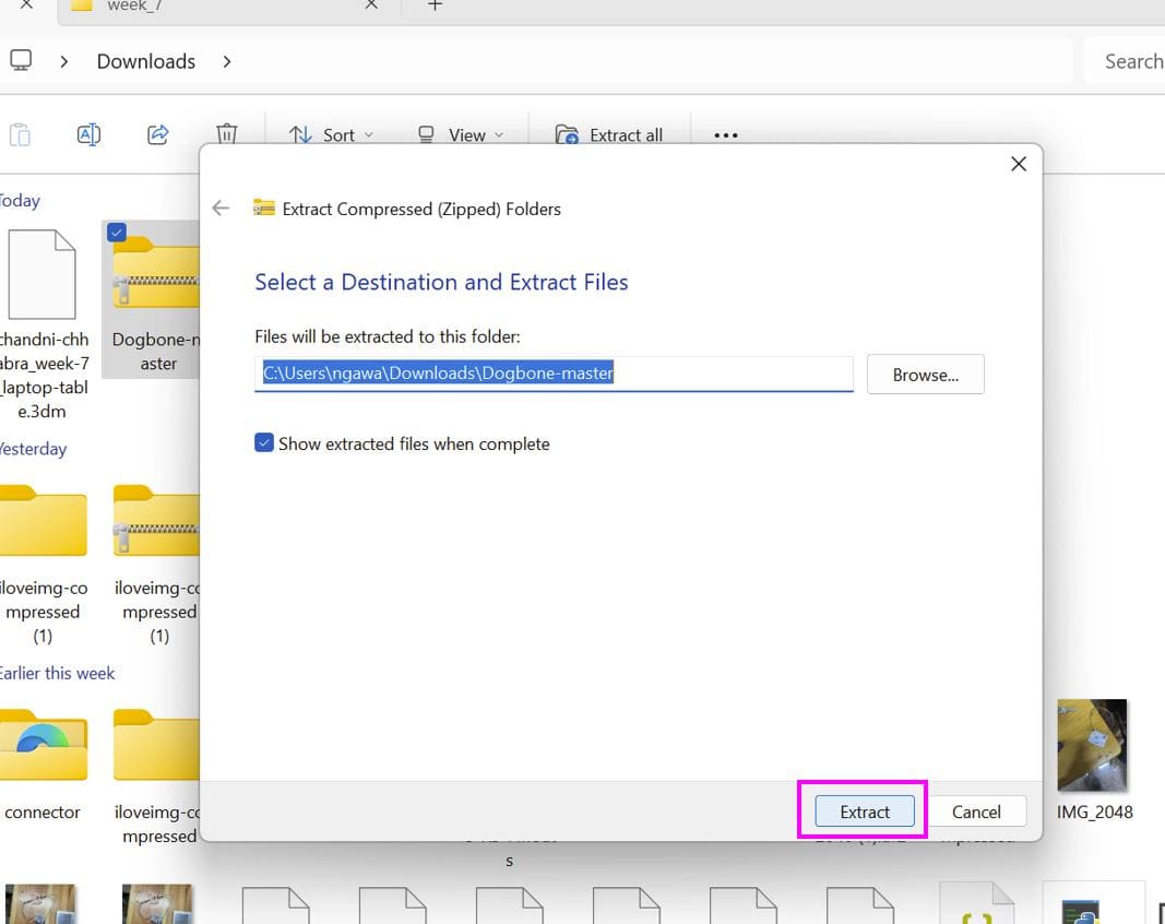
First install the zipped dogbone zipped file from this linkThen go to downloads and extract the file
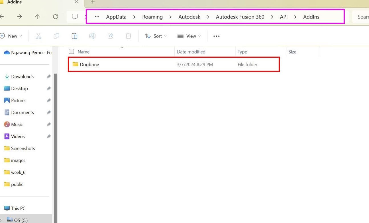
Now, copy the extracted dogbone folder and go %appdata% folder
> Autodesk > Autodesk Fusion 360 > API > AddIns. Paste the
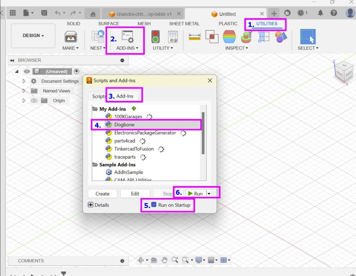
file there and you are good to go!!! Open fusion and go to Utilities >
ADD-INS > Add-Ins and select Dogbone.
Then select the Run on Startup option and finally click on Run
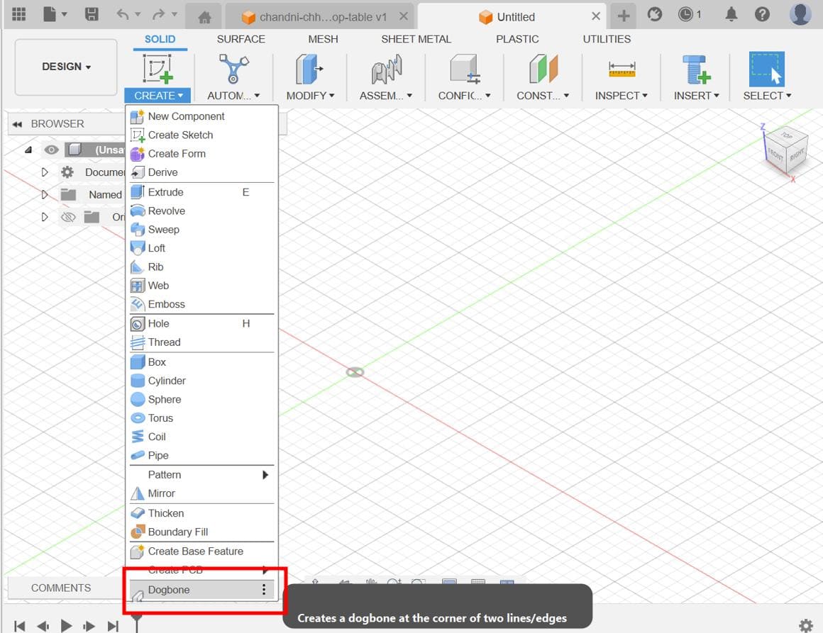
Here you can now see dogbone in the create dropdown menu
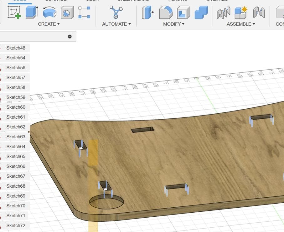
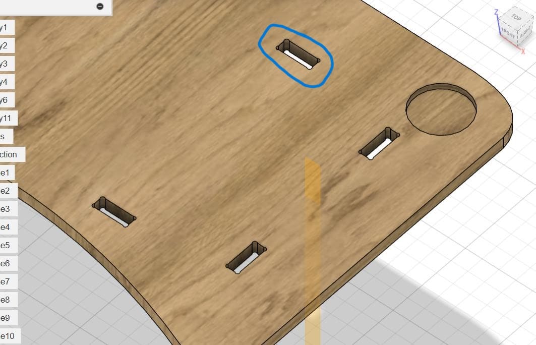
For my design, I added dogbones to all the slot edges like shown below. I kept the tool diameter as 6mm
After getting done with my design, I projected it and exported it as dxf files.
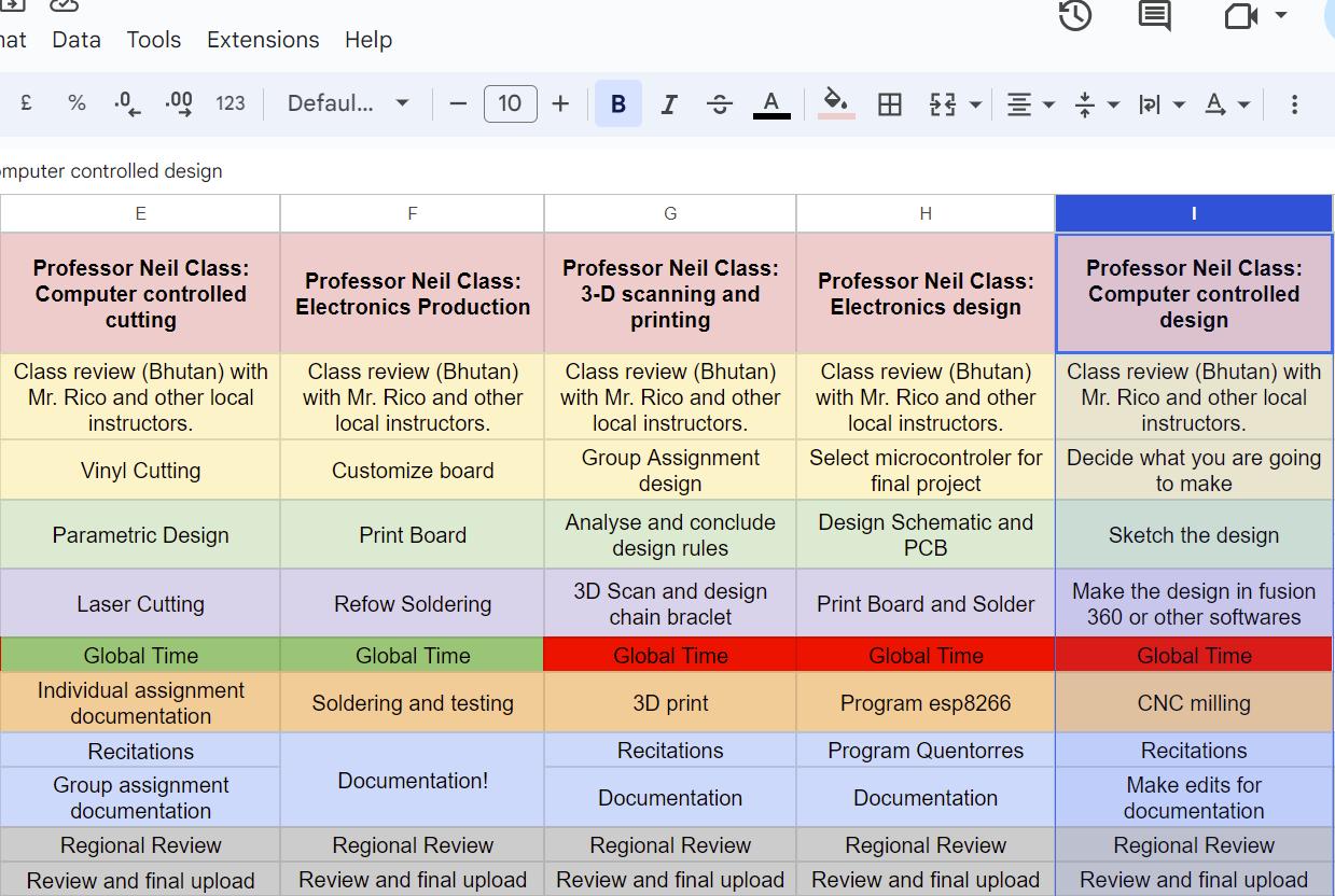
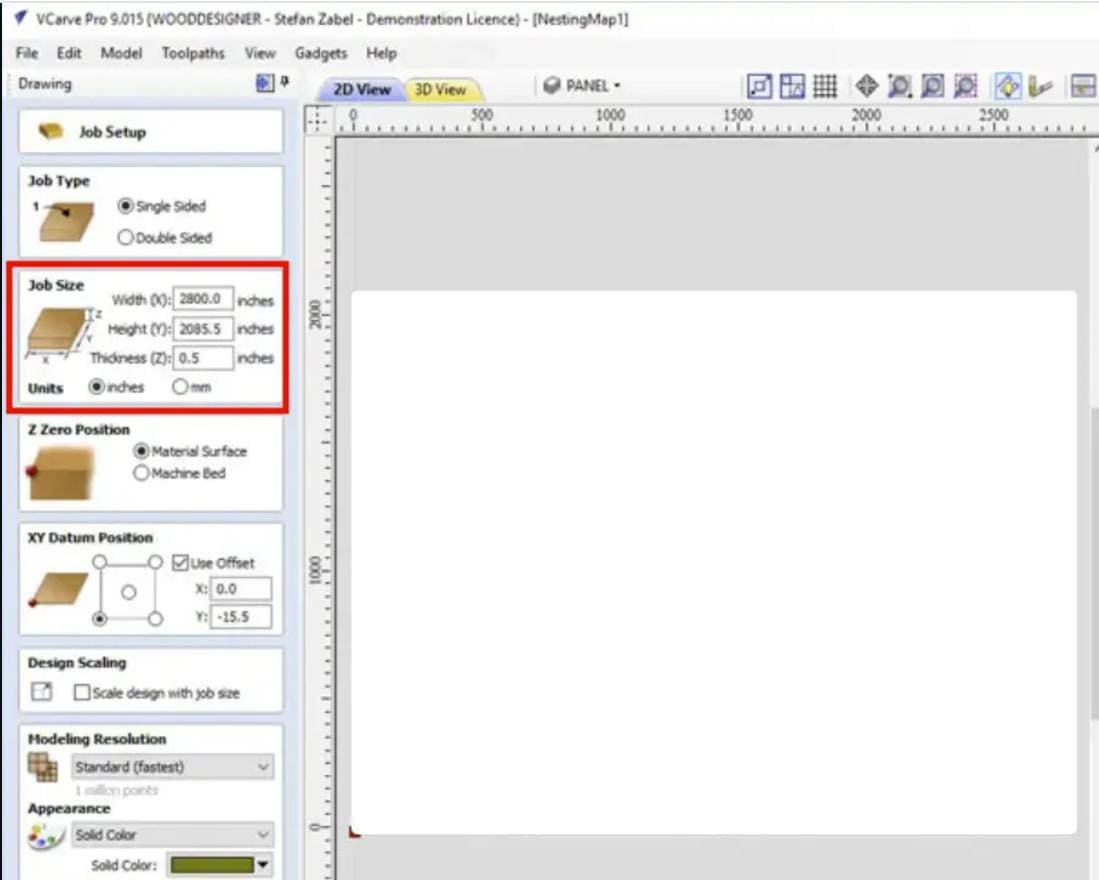
Then on the shopbot computer, I opened VCarve pro to arrange my files.
First I set the page dimensions to my actual board dimensions and also inserted the board thickness.
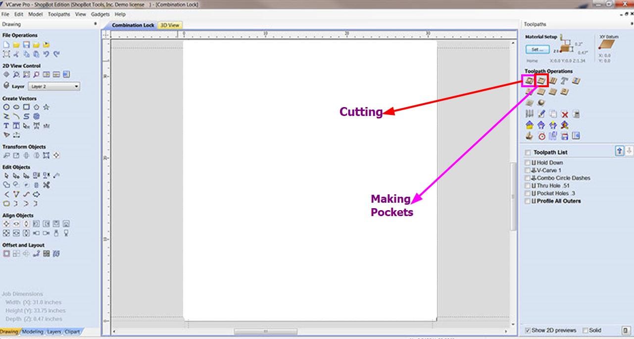
Then I pressed ok and some options for the toolpath came up. For my design, I used the first 2 options which were for cutting and making pockets. I chose the pocket making option for the cup holder as it has to be only cut halfway through the board.
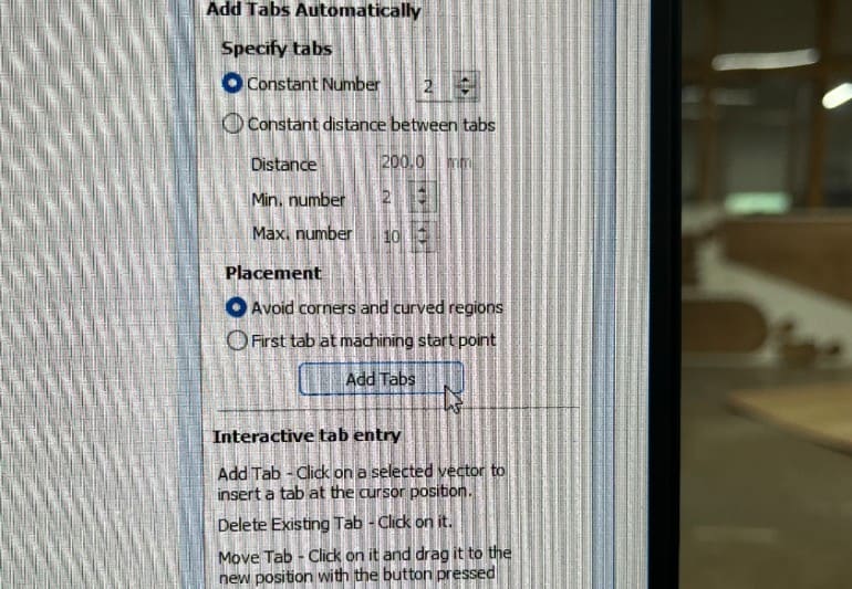
Don't forget to add tabs to avoid the components from jumping off the board and the spindle from breaking.
Endmill Selection
Choose an appropriate endmill based on material, detail level, and cut type. Consider factors like diameter, flute type, and coating.
Setting up XY-Origin
Determine the XY-Origin point, matching the machine's setup. Ensure correct XY-Origin setting in VCarve.
Start Depth and Cut Depth
Start Depth: Depth at which the tool begins cutting (usually zero).
Cut Depth: Total depth the tool cuts during a pass.
I put the machine on and presses the reset button. Then I zeroed the x and y axes. To zero the z axis, we used the
z axis touch plate method.
While setting the z axis, don't forget to attach the Touch probe alligator clip to your end-mill. Activate your machine and manually jog the machine to the middle of the touch probe about 5mm off of the probe's surface. Use the relevant software to begin the probing process and therefore zero your work piece.
Again, keep in mind to remove the alligator clip from the end mill.

After zeroing all the axes, I began the cut.
Do put on the dust collector for a clean process.
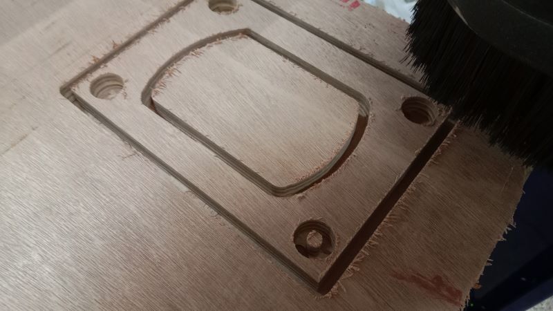
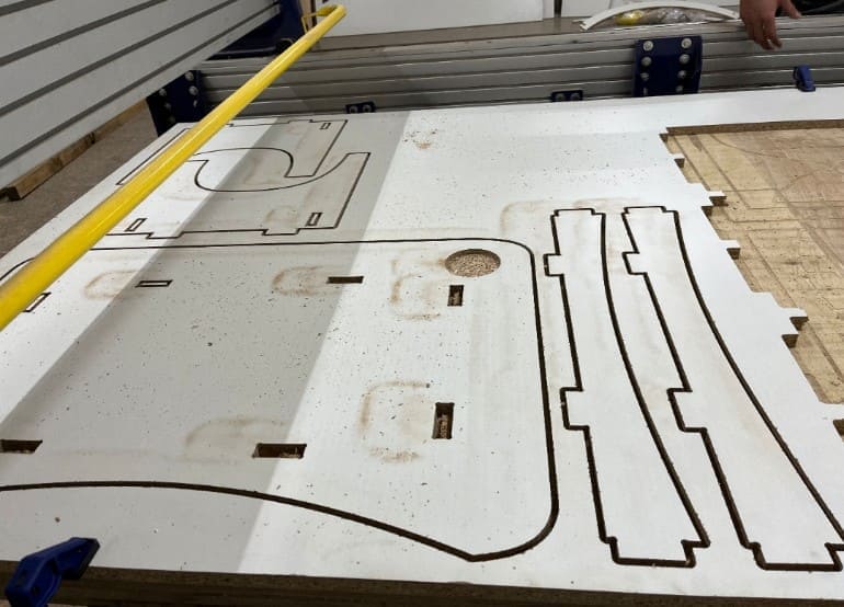
I started off with the cup holder which took around 10 mins.
Then I cut all the components which took me more than an hour.
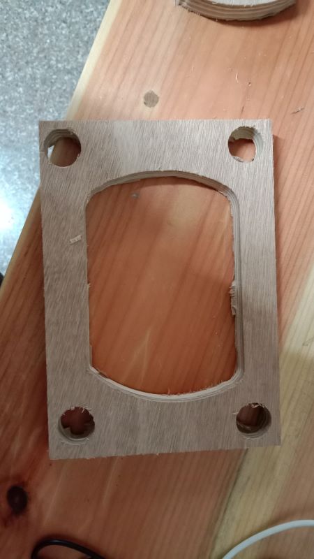
Here are the results:
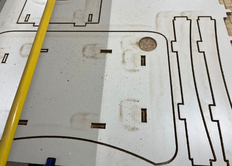
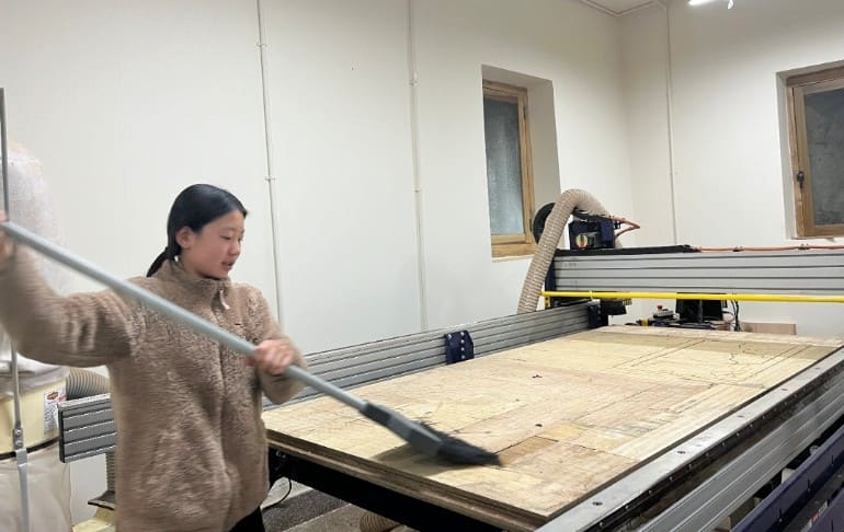
Then again please remember to clean the board to have accurate measurements and avoid any errors while cutting
The components came out pretty good and they also fit together perfectly.
Here is a video of me assembling the components.
The table didn't need any glue or other fasteners!!!