Assignment

  • Group Assignment: characterize the design rules for your in-house PCB production process
  • send a PCB out to a board house
  • Individual Assignment: make and test a microcontroller development board
  • extra credit: personalize the board
  • extra credit: make it with another process
  • All the important links are Here

    Learning outcomes

  • Described the process of tool-path generation, milling, stuffing, de-bugging and programming.
  • Demonstrate correct workflows and identify areas for improvement if required.
  • For more information, Group Assignment

    Machine

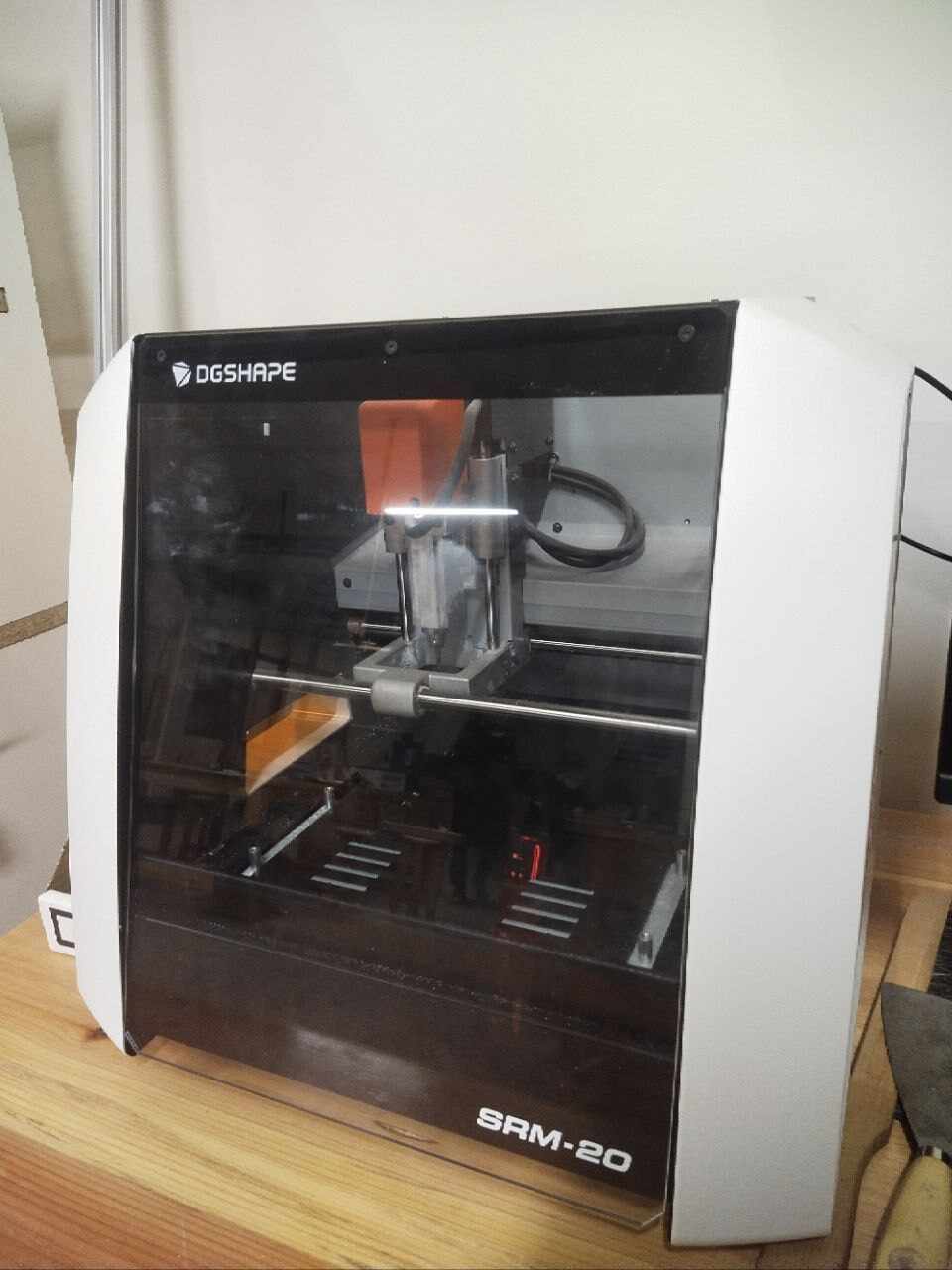
    What is Roland Mono Fab SRM 20 milling machine?

    It can mill a broad range of materials, including modeling wax, chemical wood, foam, acrylic, poly acetate, ABS and PC board. It operates by removing copper material from a blank copper-clad board, creating traces, pads, and other circuit features.

    This is the milling machine we have at our lab

    Roland Monofab SRM 20 dektop milling machine

    Image 1
    Image 2

  • Model:Roland MonoFab SRM-20 Desktop Milling Machine
  • Software:V-panel software
  • Setting:To engrave the traces, we will use the 1/64 endmill and to cut the edges we used the 1/32 endmill.
  • Tools:drilling bits; 1/32 and 1/64
  • Material:Copper board
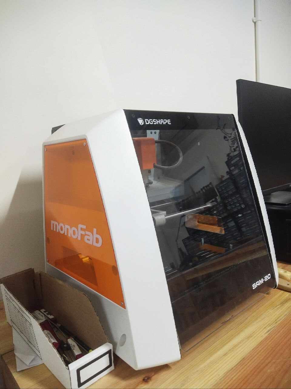
  • This is a labelled diagram of our PCB milling machine.

    Your Image Description

    The software I used is V Panel which was installed on the PC beside the Milling machine

    Before printing, we set up the settings

    Your Image Description

    Image Source

    Group Assignment

    The PCB milling machine we used at the DGI aesthetic center is the Roland Monofab SRM 20 desktop milling machine. During our collaborative project, we learned that the machine faces challenges when dealing with extremely fine lines ranging from .001mm to .010mm. Additionally, we observed that the cutting of outlines wasn't consistently smooth or complete. This issue may have arisen due to the improper adhesion of the copper plate caused by the limited availability of double-sided tapes and our team's limited experience in handling such intricacies. However, upon acquiring sufficient double-sided tapes and reattempting the process, we achieved successful results.

    Your Image Description

    Reflow

    Reflow soldering is a method used to assemble circuit boards by applying solder paste to surface mount pads, placing components onto the paste, and heating the assembly in a reflow oven. The solder paste melts, creating solder joints between the components and the PCB pads. This process ensures reliable electrical connections and is widely used for its efficiency and precision in electronics manufacturing.

    I would like to thank Mrs.Tshering Wangzom at the Super Fab Lab for teaching us how to perform this task.

    Image 1
    Image 2
    Image 1
    Image 2

    Me trying!

    Image 1
    Image 2

    Individual Assignment

    I got the following .png file of the files I used to print and customize my circuit board is the images from QuenTorres

    Image 1 Image 2 Image 3

    Since we were asked to personalize the circuit board, I simply added my initials in a fancy font. I planned on adding a logo with it but the space wass limited

    I just added the initials instead of the whole thing

    Image 3

    For the logo and lettering, I used Looka

    They gave me many options to choose from, I chose the font I liked

    Your Image Description

    Firstly, after downloading the images from the QuenTorres page, Convert the images to .svg format to have it's outline to mill on the machine.

    Your Image Description
    Your Image Description

    Then I used ModCE

    Firstly when you open the ModCE website. You will be directed to the page below, after being directed click on programs.

    Image 1
    Image 2

    Then click on open programs

    Your Image Description

    Then choose Roland SRM 20 Mill, Mill 2D PCB

    Your Image Description

    Next you wil be directed here

    Your Image Description

    Select SVG File: Start by selecting the SVG file containing the design you want to convert to RML.

    Your Image Description

    Select Mill Traces: Specify crucial milling parameters such as tool diameter, cutting depth, and spindle speed, ensuring they align with the material properties and desired machining outcomes.

    Your Image Description

    Select Add Module and Save File: Create detailed toolpaths for the milling operation and save them in RML format for CNC machine compatibility.

    Your Image Description
    Your Image Description
    Your Image Description
    Your Image Description

    Set Origin to 0: Set the origin point (0,0) in Mods CE serving as the reference for precise tool movement calculations throughout the milling process.

    Your Image Description
    Your Image Description

    Calculate Path: Calculate the toolpath and send the file to the milling device.

    Your Image Description

    After calculating the path, it will take us to a different tab which shows us the toolpath preview of the board. This is very helpful as we can detect the possible errors in the milling such as joining of different routes and others.

    Your Image Description

    Processes for Milling a PCB

    1. Prepare the Milling Bed

    1. Tape a sacrificial board onto the milling bed to secure it.
    2. Use double-sided tape to attach the desired supply firmly to the bed, ensuring it sticks well.

    2. Establishing Sacrificial Board

    A level and stable sacrificial board is crucial for milling as it ensures even and accurate cuts, preventing issues like irregularity or imprecisions in the end product.

    3. Choose and Set Up Bit

    1. Choose the appropriate bit size for the milling process and secure it in the set screw using an Allen wrench.
    2. For tracing, use a small bit like the 1/64 inch size.

    4. Machine Setup

    Prepare the Milling Bed

    1. Tape a sacrificial board onto the milling bed to shield it.
    2. Use double-sided tape to attach the preferred supply and securely attach it to the bed, ensuring it sticks well.

    Establishing Sacrificial Board

    A level and stable sacrificial board is vital for milling because it ensures even and accurate cuts, preventing issues like roughness or mistakes in the end product.

    Select and Install Bit

    1. Choose the suitable bit size for the milling procedure and secure it in the set screw using an Allen wrench.
    2. For mapping, use a bit like the 1/64 inch size.
    3. For the edge cuts, use the bit 1/32 inch

    5. Machine Setup

    1. Close the guard of the milling machine and turn it on.
    2. Set the origin point to the desired location on the supply.

    6. Bit Adjustment

    1. Loosen the bit and manually lower it until it touches the supply surface.
    2. When tightening the bit, hold it in place to prevent it from riding up.

    7. Bit Change for Cutting

    1. Replace the milling bit with a cutting bit, such as a 1/32 inch size, for the boundary cutting process.

    8. Load Cutting File

    1. Download the photo to be cut and repeat the previous steps.
    2. Make sure the appropriate RML file is selected for cutting.

    9. Set up Cutting Tool

    1. Set the PCB tool to "cut" and select the appropriate bit size for cutting.

    Milling!

    Image 1
    Image 2
    Image 1
    Image 2

    Me with the Milled board

    Your Image Description

    Now, soldering the board!

    Soldering is a process used for joining metal parts to form a mechanical or electrical bond. It typically uses a low melting point metal alloy (solder) which is melted and applied to the metal parts to be joined and this bonds to the metal parts and forms a connection when the solder solidifies.

    Steps for Soldering a PCB

    Step 1: Prepare PCB

    Clean the PCB thoroughly to remove any dust or debris. Place it securely on a heat-resistant surface to ensure stability during the soldering process.

    Step 2: Heat Soldering Iron

    Allow the soldering iron to heat up to the proper temperature, which should be between 600°- 650°F. Ensure the iron is hot enough to melt the solder effectively.

    Step 3: Solder Components

    Position the component leads in their designated spots on the PCB. Apply the soldering iron to the solder pad and the component lead simultaneously, then add solder to create a solid joint. Keep the soldering iron tip clean by wiping it on a wet sponge or brass wool ball to prevent oxidation.

    Step 4: Test Connections

    Once all components are soldered, test the connections with a multimeter or power up the circuit to check for proper functionality. Ensure the PCB is disconnected from any power source before testing. Set the multimeter to continuity mode, where it emits a sound or shows a low resistance reading when a circuit is complete. Place one probe on a point (such as a component pin or PCB trace) and the other probe on the second point to check for continuity. A continuous path indicates proper connectivity, while a high resistance reading suggests breaks, shorts, or faulty connections. This test helps in identifying issues and ensures the PCB operates correctly.

    Firstly the components, Sorry I forgot to include the 3 LEDs I used.

    Your Image Description
    Image 1
    Image 2

    Now photo session with the boards!!

    Image 1
    Image 2

    Testing!

    Firstly, open your Arduino IDE

    You will be needing the below URLs

    https://github.com/earlephilhower/arduino-pico/releases/download/global/package_rp2040_index.json https://raw.githubusercontent.com/espressif/arduino-esp32/gh-pages/package_esp32_index.json

    Image 1
    Image 2

    Add the URLs I mentioned above here

    Your Image Description

    Then open the arduino Blink file

    Image 1
    Image 2

    Downloading Pico, because it is needed for the QuenTorres board

    Image 1
    Image 2

    Before uploading,make sure to do the following

    Image 1
    Image 2
    Image 1
    Image 2
    Your Image Description

    Me done with this week's assignment

    Your Image Description

    My files

    My .rml zipped file All are in the zipped file

    My .svg zipped fileAll are in the zipped file