Group Assignment
Group Assignment Link:
____________
Seeed Studio XIAO Programming

Downloaded Arduino IDE on my home PC Desktop and agreed to Trust Installation.
Seeed Studio Xiao RP2040 Datasheet
(As Described by ChatGPT v.4o, 30th June, 2024)
The Seeed Studio Xiao RP2040 is a compact and powerful microcontroller board based on the Raspberry Pi RP2040 chip. Here’s a brief overview:1. Processor: It features a dual-core ARM Cortex-M0+ processor, capable of running at up to 133 MHz.
2. Memory: The board includes 264 KB of SRAM and 2 MB of onboard flash memory.
3. Connectivity: It offers a variety of I/O options, including 11 digital I/O pins, 4 analog input pins, and 1 analog output pin. It also supports UART, I2C, and SPI communication protocols.
4. Size: The Xiao RP2040 is very small, measuring just 21 x 17.5 mm, making it ideal for compact projects.
5. Power Supply: It can be powered via a USB-C port or through its pins, with a wide input voltage range of 3.3V to 5V.
6. Programming: It is programmable using the Arduino IDE, CircuitPython, and MicroPython, providing flexibility for different coding preferences.
7. Additional Features: The board includes a reset button, and an RGB LED for basic feedback and status indication.
Overall, the Seeed Studio Xiao RP2040 is well-suited for applications requiring a small form factor and sufficient processing power, such as wearable devices, compact robots, and various IoT projects.
____________
Arduino Uno R3 Datasheet
(As Described by ChatGPT v.4o, 30th June, 2024)
The Arduino Uno R3 is a widely used and versatile microcontroller board, popular in the maker and educational communities. Here’s a brief overview:1. Processor: It is powered by the ATmega328P microcontroller, an 8-bit AVR processor running at 16 MHz.
2. Memory: The board includes 2 KB of SRAM, 32 KB of flash memory (with 0.5 KB used by the bootloader), and 1 KB of EEPROM.
3. Connectivity: It offers 14 digital I/O pins (6 of which can be used as PWM outputs) and 6 analog input pins. It supports UART, I2C, and SPI communication protocols.
4. Size: The Uno R3 measures approximately 68.6 x 53.4 mm, with a standard pin layout that is compatible with many shields and expansion boards.
5. Power Supply: It can be powered via a USB-B port, an external power jack (7-12V), or through its Vin pin (6-20V). The onboard voltage regulator provides 5V and 3.3V outputs.
6. Programming: The Uno R3 is programmable using the Arduino IDE, which supports C/C++ programming. It connects to a computer via a USB-B cable for uploading code and serial communication.
7. Additional Features: The board includes a reset button, an ICSP (In-Circuit Serial Programming) header, and an onboard LED connected to pin 13.
Overall, the Arduino Uno R3 is ideal for beginners and experienced developers alike, suitable for a wide range of applications, including prototyping, learning electronics, and developing interactive projects.
References for getting started:
- Microcontroller
- Seeed XIAO Tutorial
- Quentorres Information
- Arduino IDE Download
- Beginners Guide to Electronics
____________
Individual Assignment
____________
Wednesday Meeting Reflection
I watched the entire debriefing of this week’s assignment and understand maybe 1-5% of it. This week is either going to be simple enough and I’m overcomplicating things OR it may be one of the most difficult weeks for me in Fab Academy.
Oscar’s words of wisdom: “Program using Arduino IDE, as it’s made for mortal men.”
____________
Monday Recitation Notes
MicroController - explained by Nicolas De Coster.
When choosing your microcontroller, Consider:
- Processing power,
- Memory
- I/O capabilities
- Power consumption
- Existing libraries / support.
Examples: AtTiny412, Seeed Studio Xiao RP2040, ESP32-C3
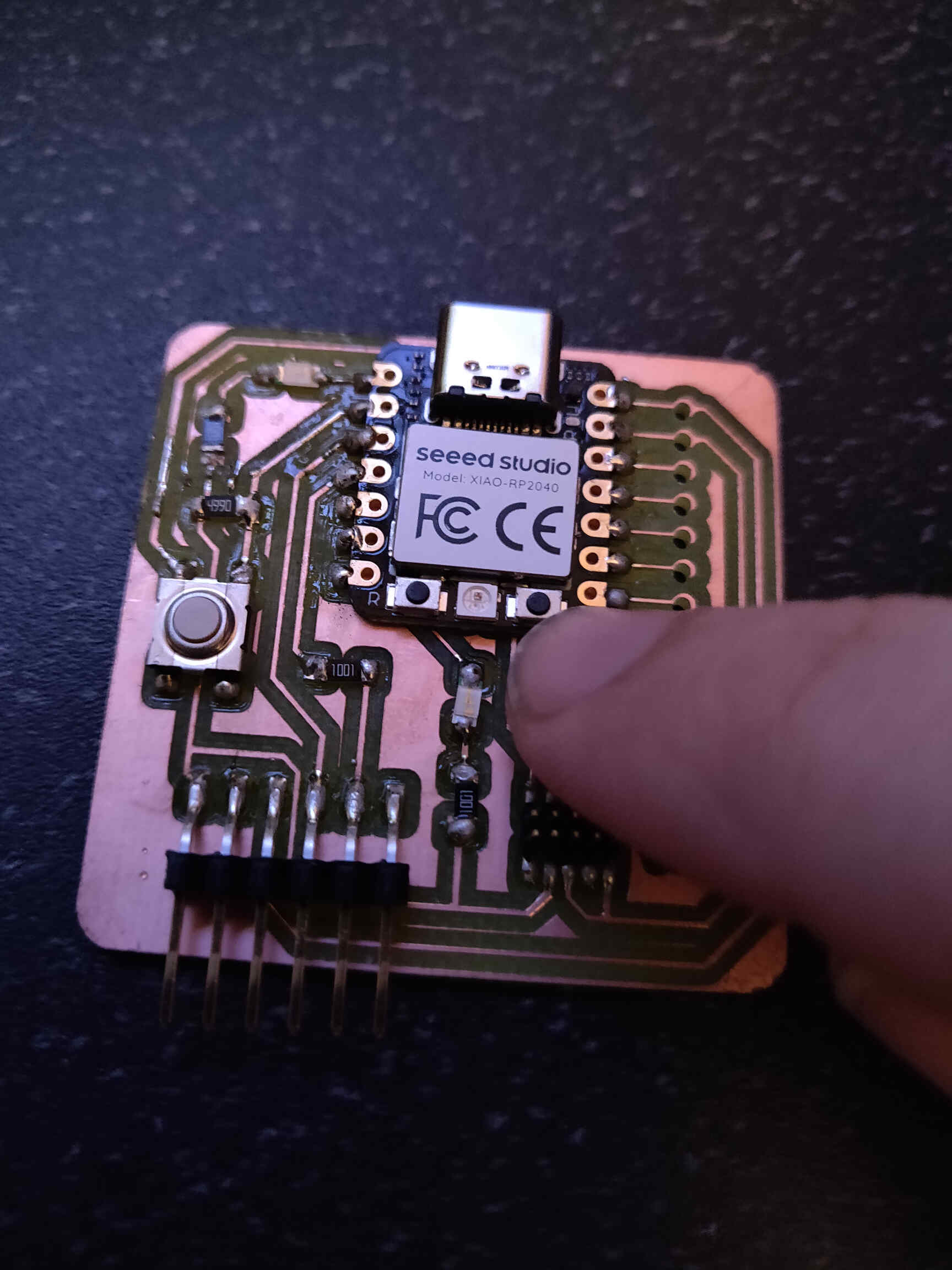
Seeed Studio Xiao RP2040 is the microcontroller we used for our Quentorres board.
Developed by Raspberry Pi, dual core ARM Cortex-M0+
Quick Mentions:
Hardcoded bootloader - XIAO module or RPi Zero. Sandbox: FabXIAO.
Program through UF2. (Just plug into USB)
Always refer to the microcontroller’s datasheet.
Choose language - ASSEMBLY / PIO / VHDL / VERILOG...
Learn binary / logic basics! (worth it! … supposedly)
Arduino is C++ based. MicroPython & Javascript are also a high level language for microcontrollers.
Direct Programming: UPDI / ISP / SWD / JTAG - Send to the chip.
Bootloader: Didn’t understand a word, but might be important. (it was...)
HardCoded Bootloader (UF2)
“One Programmer to rule them all”: Quentorres.
Arduino (C/C++) Knowing the difference…
Arduino Uno = Board = Hardware. Arduino is a set of libraries. “Pure C” vs Arduino.
Arduino IDE is a development environment. Document your code! Use “ // “ to comment.
Write Parametric and/or use Classes. (like HTML)
____________
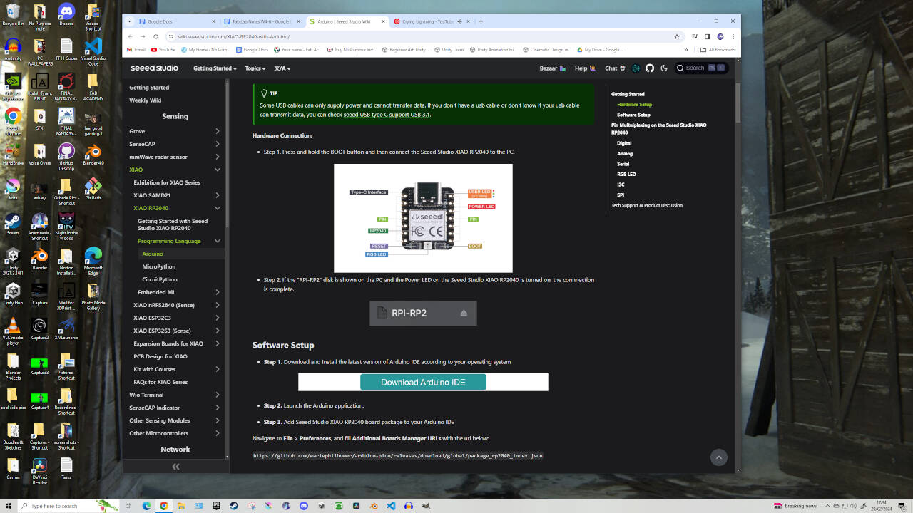
Arduino IDE Programming tutorial
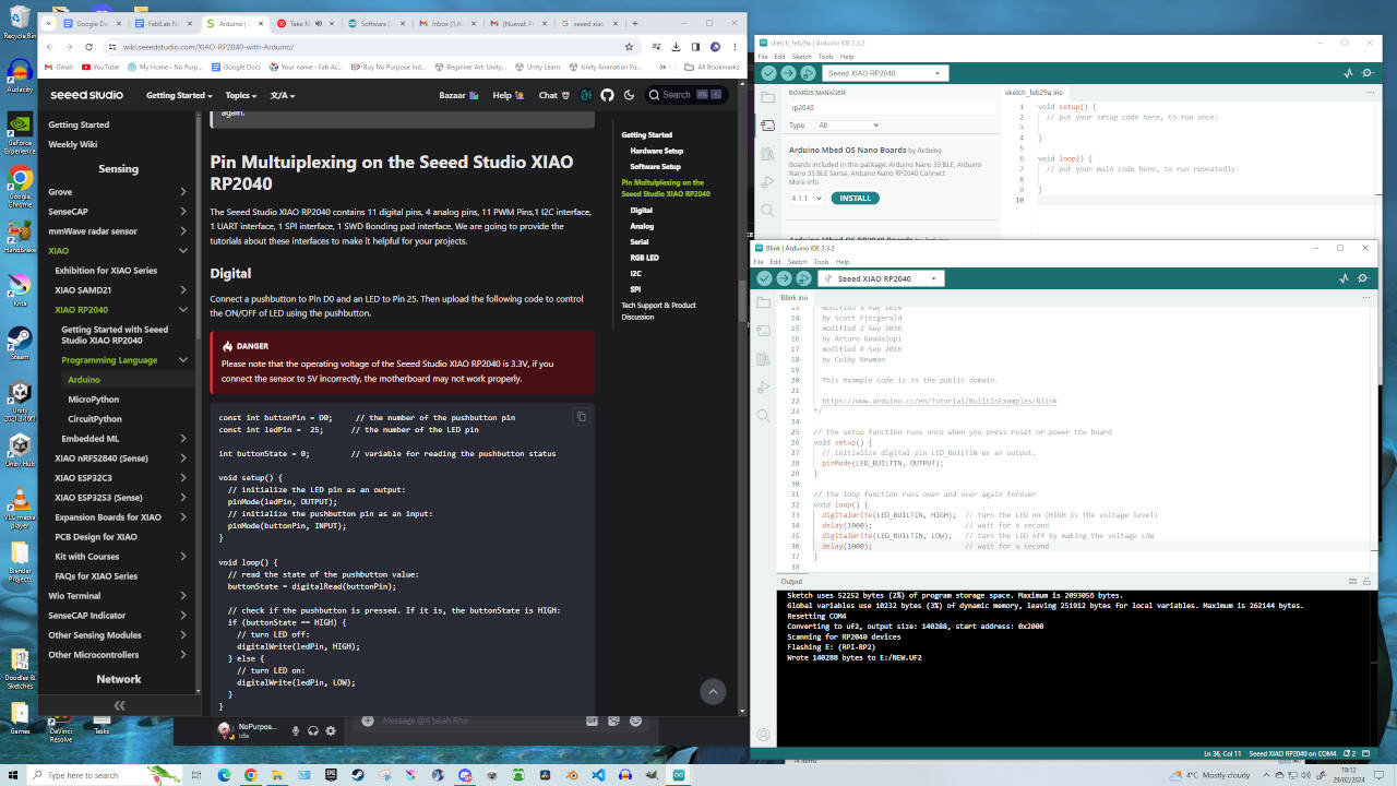
Went to Tools -> Boards -> Board Manager. Typed "RP2040" and installed the board labelled “Raspberry Pi Pico/RP2040” and agreed to installation. Then I went back to Tools -> Boards -> Then selected ‘Raspberri Pico/2040 -> Then ‘Seeed XIAO RP 2040’. Additional Boards can be added by going to Preferences -> Additional Boards Manager.
(Copy & Paste Github links you have into the "Additional Boards Manager" box.)
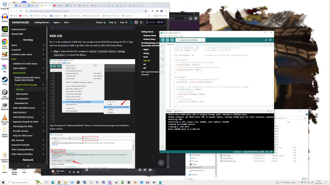
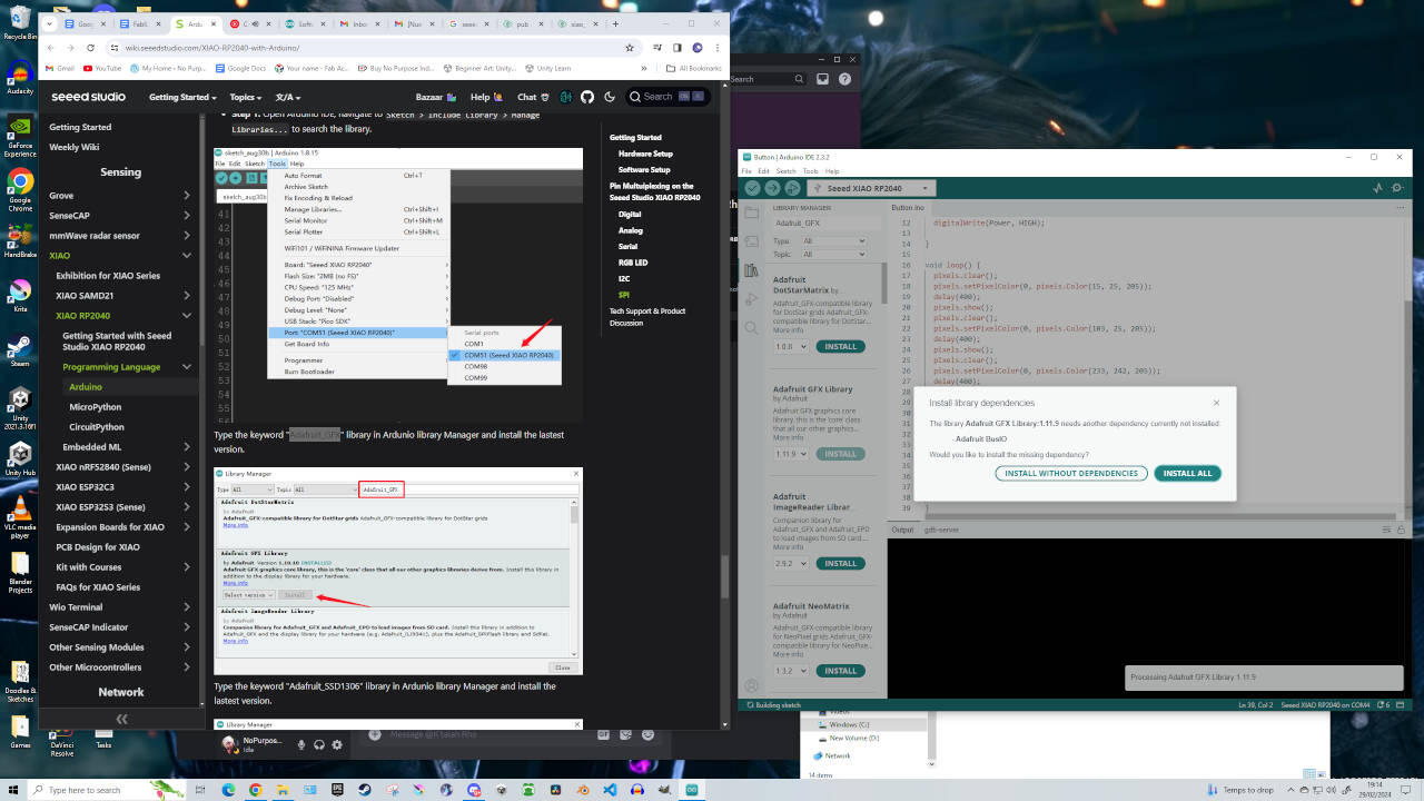
After this I went to Tools -> Port -> Selected COM3. The tutorial I followed said a port labelled ‘COM5(Seeed XIAO RP2040)’ would appear but I didn’t get the option. Though after some small research COM3 is what we are also looking for. That being said, my selection of COM3 changed itself to COM4 shortly after.
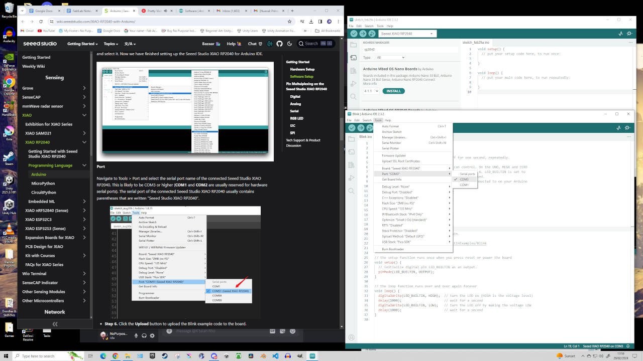
EDITORS NOTE: I can't help but laugh when reviewing this documentation weeks later. COM Ports change all the time depending on the laptop port - just keep selecting whichever appears until it's the one you need.
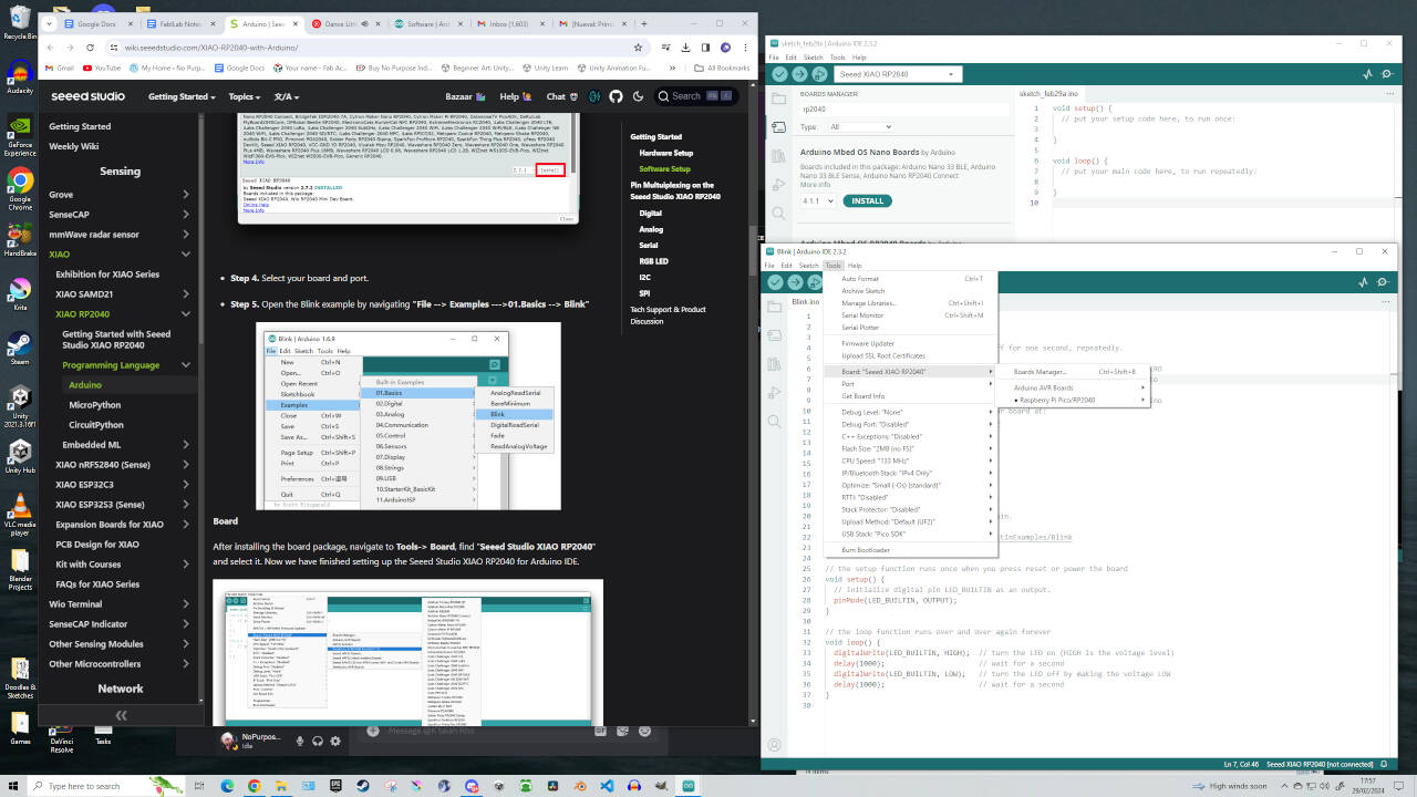
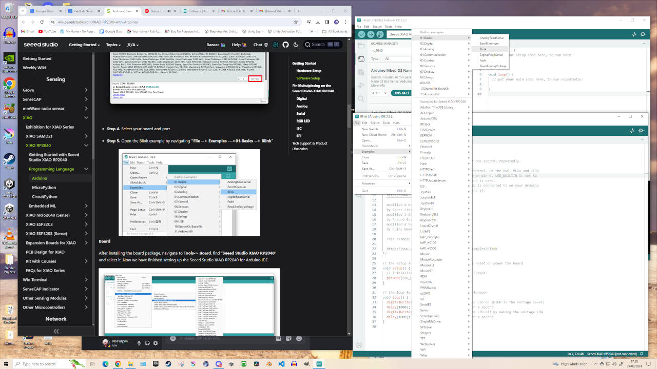
Beginning with the 'Blink' Test
The 'Blink' test is considered the very first step on your programming journey. Using code from Arduino IDE's Examples, this will tell the microcontroller to activate the connected (or Built-In) LED light on and off every second. When following this tutorial and performing the "Blink" test example, the tutorial documented that Pin 25 would blink once per second upon upload. Although there was certainly a light blinking on the Seeed XIAO board, I couldn’t really tell if it was because of me or if it was just lighting up for another reason - such as a connection fault.
To test this, I changed the Arduino IDE delay code from 1000 -> 200. That way the light would blink every fifth of a second. After upload, I can confirm the light blinking was from the Blink test - meaning the connection to my own manufactured board is successful!
Can’t celebrate yet though. I attempted the Digital Button test, both through copying & pasting the code from the tutorial and also by opening the Test Example from Arduino IDE. Both resulted in failure. The test is supposed to allow the LED light connected to pin 25 to be controlled at the touch of a button connected to pin D0, yet pressing and/or holding the button on my Quentorres PCB had no effect. I’m concerned that my initial soldering failures (as documented on the Week 4 Assignment page) may have weakened or caused a break in the connection between the microcontroller and the button.
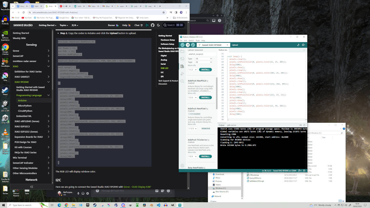
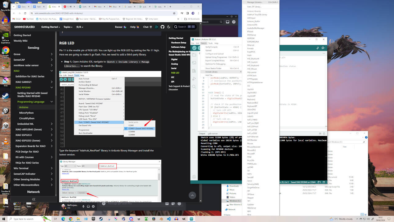
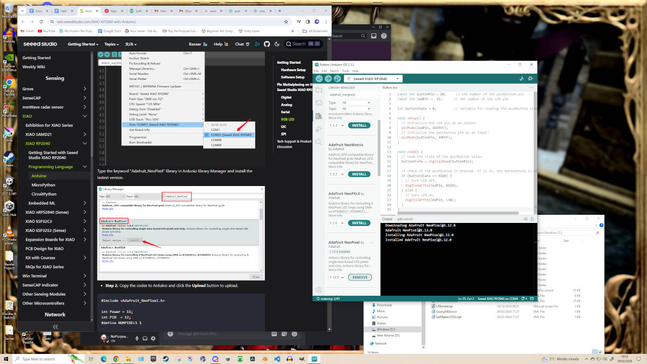
I attempted the Analog and Serial tests but without the correct components, they revealed nothing visible. However, following the tutorials, I attempted the RGB LED Test which would apparently flash the LED rainbow coloured. To do this, i went back to Arduino IDE and selected Sketch -> Include Library… -> Manage Libraries. Then in the Search tab typed in ‘adafruit_neopixel’ and installed the Adafruit NeoPixel library. After copying the code and uploading, the LED at the bottom of the microcontroller starts flashing different colours (Red, Blue, Purple, Yellow, etc).
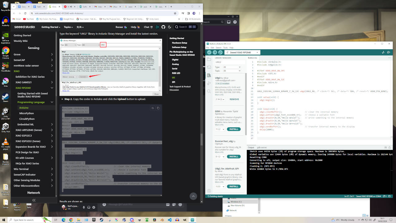
For the next test, we are going to connect the microcontroller with ‘Grove - OLED Display 0.96 (SSD1315)’ through IIC and display the text ‘Hello World’. I didn’t have the OLED to prove this test but I followed the tutorial either way. In Arduino IDE select Sketch -> Include Library… -> Manage Libraries. Then in the Search tab typed in ‘u8g2’ and installed the ‘U8g2 by oliver’ library. After copying this code and uploading, you should see the ‘Hello World’ text appear on your OLED screen.
Now we are going to connect the microcontroller with ‘Grove - OLED Display 0.96 (SSD1315)’ through SPI and display the text ‘Hello World’. In Arduino IDE select Sketch -> Include Library… -> Manage Libraries. Then in the Search tab typed in ‘Adafruit_GFX’ and installed the ‘Adafruit GFX Library’. A pop up came up for me saying this library needs another dependency that isn’t currently installed named ‘Adafruit BusIO’, which I agreed to Install All.
Then in the Search tab typed in ‘Adafruit_SSD1306’ and installed the ‘Adafruit SSD1306 Library’. A pop up came up for me saying this library needs another dependency that isn’t currently installed named ‘Adafruit BusIO’ and ‘Adafruit GFX’, which concerns me since those libraries were JUST installed. Still, I agreed to Install All. I later discovered that this is a regular occurance when working on multiple computers or new files.
After copying the code and uploading, the text ‘Hello World’ should now appear through your SPI. Congrats! With the tutorial done, I awaited the next direction from my instructor.
EDITOR'S NOTE: I could not take photos of OLED working as our fablab did not have any Groove OLED's at the time. Also I was told that I am veering off from the assignment and so was given further guidance.
____________
Major Struggles:
I returned to Fablab the next day to install all the Arduino libraries on the fablab laptop and access the OLED components needed to complete the ‘Hello World’ tests, but ran into some trouble. My board couldn’t be recognised by my fablab laptop, nor could it be accessed by my instructor's PC. I’m not sure when but it seems my PCB has been damaged or viable connections were lost. I’m pretty much at a loss on what to do now.
EDITOR'S NOTE: This issue ended up persisting at multiple occasions throughout my fablab journey leading to certain assignments snowballing.
Slight Update - I managed to reconnect the PCB to the computer. The USB port seems faulty as I need to angle the wired connection just right so that it won’t disconnect. But even so, either my push button connection is faulty or there is something wrong with my code. I tried looking up what I could to fix the issue but all I get in return is hundreds or thousands of pages of possible details or code variations or troubleshooting for other components and none of it makes sense to me.
Before, during other weekly assignments, I felt under pressure due to not having enough time. But now I’m under pressure as I have absolutely no idea what I am looking at or what I am supposed to do.
EDITOR'S NOTE: This ended up being an issue with improper soldering. There were 2 pinout disconnections that needed resoldering as the metal was on the trace but barely touching the microcontroller.
Major Update: Oh my god, it’s working! Let’s get back to the tutorial.
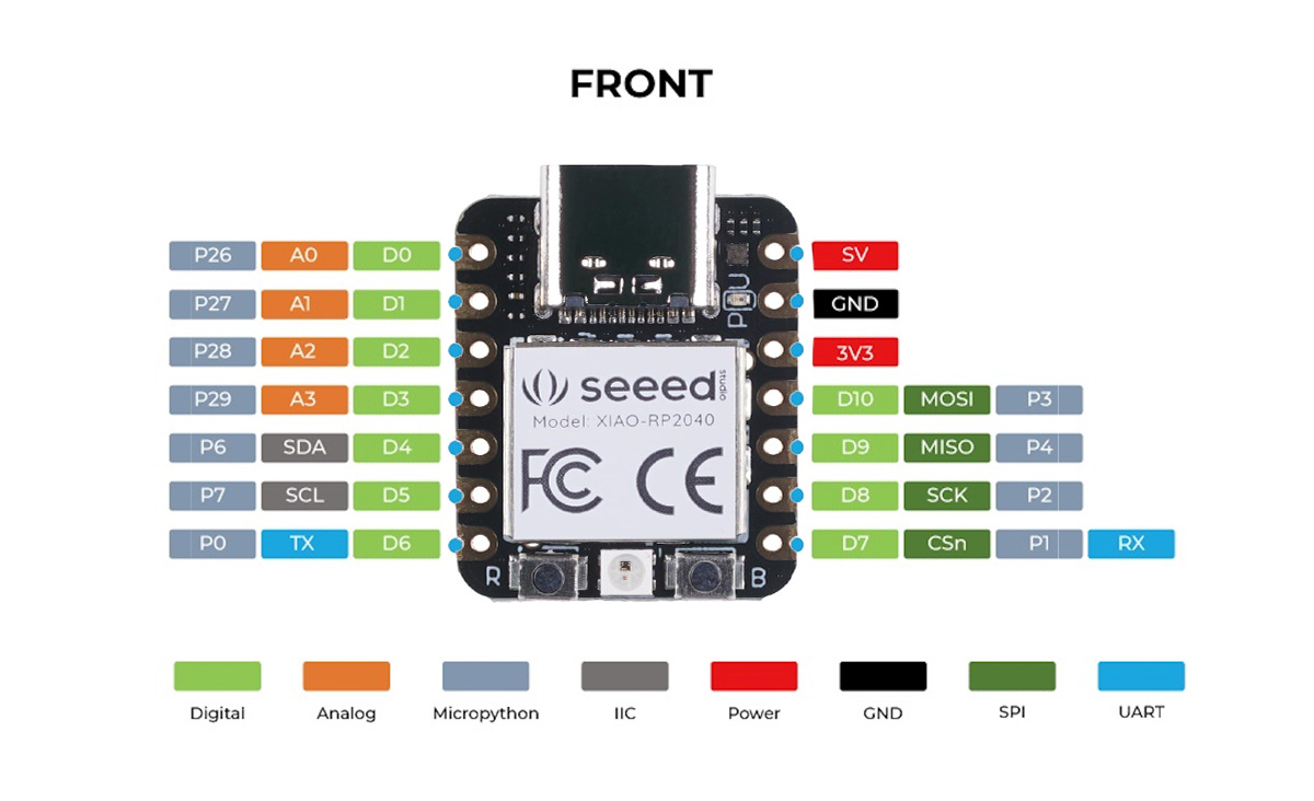
My instructor referred me back to the datasheet to examine which pins on the Seeed Studio XIAO RP2040 microcontroller are connected to which components on my PCB. Oscar pointed out to me that currently my LED is connected to Pin D0, while the Button is connected to Pin D1.
____________
At the top of the Push Button Example Code, you should see this code:
const int buttonPin = D0; // the number of the pushbutton pin
const int ledPin = 25; // the number of the LED pin
To get my button work, I changed the code to:
const int buttonPin = D1; // the number of the pushbutton pin
const int ledPin = D0; // the number of the LED pin
These were the correct paths for my Quentorres PCB. Now everytime I push the button, the LED will light up.
With this step complete, I now need to add a Serial Code that will communicate with another Wired or Wireless Device. For now, I’m going to click on the Serial Monitor on the top right of the Arduino IDE to open up the Serial Monitor. On the right hand side of the serial monitor (found below your code) we need to change the baud to “115200” to allow the connection for communication. Oscar described 'Baud settings' to me as picking the right frequency for a Radio. Once this was done, I added the following code to Arduino IDE…
____________
Serial Communication Test - In the ‘void setup’ add this code:
while (!Serial);
In the ‘void loop’ add this code:
Serial.println("Hello,World");
delay(1000);
If done correctly, the code should look like this:
const int buttonPin = D1; // the number of the pushbutton pin
const int ledPin = D0; // the number of the LED pin
int buttonState = 0; // variable for reading the pushbutton status
void setup() {
// initialize the LED pin as an output:
pinMode(ledPin, OUTPUT);
// initialize the pushbutton pin as an input:
pinMode(buttonPin, INPUT);
Serial.begin(115200);
while (!Serial);
}
void loop() {
// read the state of the pushbutton value:
buttonState = digitalRead(buttonPin);
// check if the pushbutton is pressed. If it is, the buttonState is HIGH:
if (buttonState == HIGH) {
// turn LED off:
digitalWrite(ledPin, HIGH);
} else {
// turn LED on:
digitalWrite(ledPin, LOW);
}
// Adding Serial
Serial.println("Hello,World");
delay(1000);
}
Our next objective is to have the Serial Monitor say ‘Hello World’ every time I press the button on the PCB. This was done quite easily by removing the ‘delay(1000);’ code and moving ‘Serial.printIn(“Hello,World”);’ to inside the ‘if’ statement.
____________
Serial Communication through PushButton Input - The code should look like this:
const int buttonPin = D1; // the number of the pushbutton pin
const int ledPin = D0; // the number of the LED pin
int buttonState = 0; // variable for reading the pushbutton status
void setup() {
// initialize the LED pin as an output:
pinMode(ledPin, OUTPUT);
// initialize the pushbutton pin as an input:
pinMode(buttonPin, INPUT);
Serial.begin(115200);
while (!Serial);
}
void loop() {
// read the state of the pushbutton value:
buttonState = digitalRead(buttonPin);
// check if the pushbutton is pressed. If it is, the buttonState is HIGH:
if (buttonState == HIGH) {
// Adding Serial when button is pressed
Serial.println("Hello,World");
delay(1000);
// turn LED off:
digitalWrite(ledPin, HIGH);
} else {
// turn LED on:
digitalWrite(ledPin, LOW);
}
}
With that done, I now need to communicate with the PCB with the Controller. To prepare for that, I need to download the drivers from this link in order for the controller to work with my laptop.
Link to drivers and info
From the provided link, click the MPLAB X IDE link then click on the button “Download MPLAB x IDE” and pick your appropriate system to get the drivers required - in my case ‘Windows’. During the install process, just agree to the default settings and install.
Prepare yourself, this will be installing for a long while, as well as asking you install others.
Part of the assignment is that I CAN’T use a breadboard to communicate with my Arduino / Quentorres to complete the assignment - I can only use it for Prototyping. I can get the Arduino to communicate with the Quentorres directly, but again - only for prototyping. I had also decided to manufacture and produce am AtTiny412 board which I could activate using the Programmer and communicate with my Quentorres board.
We ran into complications (myself and my instructor) activating the AtTiny412 board using the programmer and the links / drivers provided, leading us to contact Nulea (fab academy instructor) for advice and/or specialised help. I would have loved to get a 1 on 1 session with an expert in Electronics and Programming as it could have prevented a lot of electronic assignments from snowballing into each other, but unfortunately that wasn't the case. We did however recieve an insight into other students work and fixes that they've found along with alternatives for activating boards.
EDITOR’S NOTE: We discovered through Nulea's advice that other students have been designing boards with Seeed Studio Xiao RP2040 Microcontrollers as it comes out of the box pre-programmed. There's no need to activate the board using a programmer - just a need to 'reboot' the board which takes no time at all - (Done by holding the button labelled 'R' when connected via USB, then quickly press the button labeled 'B' to reboot the Xiao RP2040). It was advised to me that it's better to use other microcontrollers as Seeed Studio Xiao's are costly at €5 a piece. However, I don't mind paying extra as long as it removes complications and roadblocks from my path.
____________
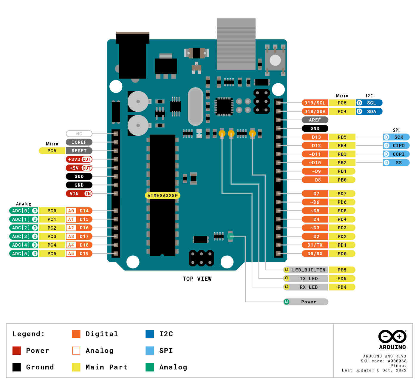
Communication between Quentorres and Arduino Uno
Attempted to get Quentorres to speak with the Arduino Uno.
I could get the Serial Monitor to say Hello World constantly, and say it only when the Quentorres button was pushed. But I kept failing to get the Push Button on the Quentorres to turn on an LED light on an Arduino or AtTiny.
EDITOR’S NOTE: We scrapped the idea of using the programmer to activate the PCB as we ran into a ton of wiring and compatibility issues. We have yet to activate the AtTiny board as we discovered the lack of need for it. We continued the assignments using RP2040 & ESP32-C3 microcontrollers. We also discovered that this week's assignment was not looking for communication between two boards - it was looking for a board to communicate with an Input & Output Device. I didn't think the Fab Academy Week 6 Assignment Brief explained this clearly.


Editor’s Note: Frustration and Failures
Spent days trying to get the serial communication to work and led to failure, stress and a lot of wasted time spent debugging with no solutions.EDITOR’S NOTE 1: I made the unfortunate mistake of "git reverting" my webiste through Git Bash after reaching the 10mb upload size limit set for the students. After some research I thought that executing a 'git revert' would un-commit my last upload and make space for my update upload size. However, what this did was revert my website on my hard drive to the website's previous state. Meaning I had just lost over 6 hours of documentation work and deleted a lot of the photos & screenshots I took. What you've viewed up until now has been the result of data and images being scavanged back together - thus there may be inconsistencies.
EDITOR’S NOTE 2: I had to leave the completion of this assignment as I totally ran out of time with no success on the horizon and my confidence deflated. Any success on this assignment from hereon would have been done weeks later. The benefit of running into so many complications during my Electronics / Programming weeks is that when I finally returned to these assignments, I gained experience and knowledge overtime of debugging issues and fixing broken connections. Unfortunately not enough to exceed in this field - only to pass the finish line.
Here's some further references that details communications and connections:
Communication between 2 Arduinos Weam Alghamdi Student Example Networking and Communications Explaination Arduino Datasheet

Returning to Finish the Assignment
Went back to fix the soldering on the Quentorres, then eventually during ‘Outputs’ week, with Oscar’s help, I was able to get my Quentorres to control a Servo Motor and use a Potentiometer to control its speed and direction, then for Machine Building week we utilized that procedure to create a Rotary Pub that connects to the FMCU.
From here I was able to get a better understanding of Circuit Boards, Inputs & Output Devices (through many long and unforgiving failures), and what it is exactly the assignment asks of me.
Below you can find video footage of me performing a multitude of communications tests, along with progress towards my final project's functionality. The Source Code for each test can be found in the Project Files Zip Folder at the bottom of the page.
____________
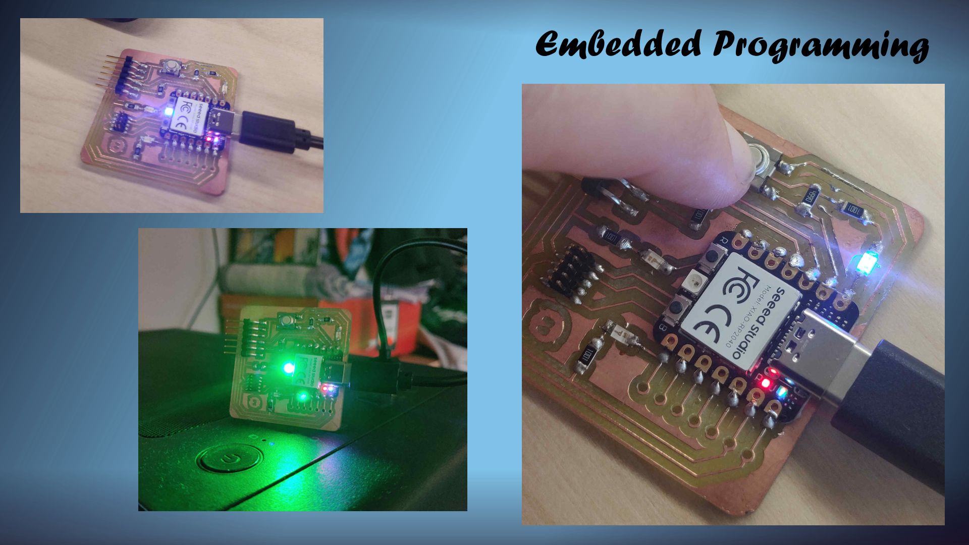
Performing Embedded Programming Tests
Built-IN LED Blink & RGB LED Test
____________
Pushbutton Communication / Hello.World Test / Serial Monitor Test
____________
Communication with Input & Output Devices
Microcontroller Communication with Input and Output Devices was performed using a Seeed Studio Xiao RP2040 Microcontroller w/ a Hall Effect Sensor and Servo Motor.Adjusting Code for Final Project's "Acknowledgement Animation".
____________
Conclusion & Thoughts
This week was a struggle as I found the embedded programming end of things quite taxing on my own confidence. For design weeks my frustrations come from a large workload / documentation that I leave myself as I try to learn and improve upon my on skills and experience. When it comes to Electronic / Programming weeks, I find even the smallest request overly daunting. I am familiar coding with HTML and coding for Event Cinematics in gaming, but when I'm tasked with adapting code I am unfamiliar with, I'm basically a deer in headlights - too freaked out to make a move.
The most intimidating part is when I ask for help and the response is usually "Refer to the Datasheet" - which would be hundreds of pages long and filled with information I don't understand. That being said, with all the debugging issues I've faced, it's undeniable that I am retaining some valuable information. I feel comfortable now with understanding the microcontroller pinout, how traces and electrical current works, types of microcontrollers / inputs / outputs, etc.
I am certainly learning but at a very slow pace - which causes complications with weekly deadlines approaching. From this point on I'll just make sure to keep it very simple and stick to the assignments requested rather than putting time into experimentation. I think it's also time I look towards restricting the capabilities of my final project's functionality. As much as I want to exceed my own expectations and strengths - I know where my weaknesses are and know when I'm beat. For these programming weeks I'll just need to make sure I keep my head above the water.
____________