Week 10 - Mechanical Design / Machine Design

Group Assignment:

  • Design a machine that includes mechanism+actuation+automation+application
  • Build the mechanical parts and operate it manually
  • Document the group project and your individual contribution

  • Group Assignment Link:

  • Click HERE to view Group Assignment Page!

  • ____________


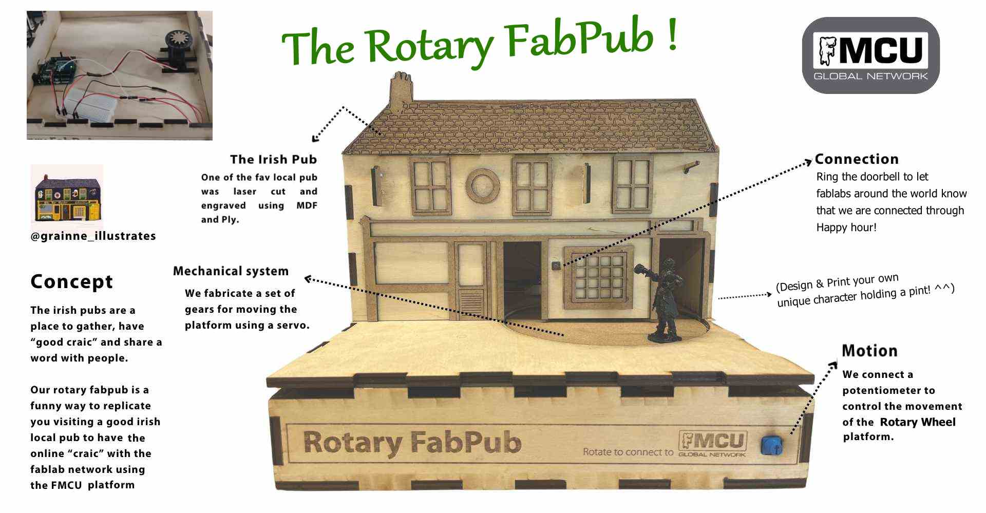
    Our Machine: The Rotary FabPub!


    ____________

    Assignment Progression

    For Group assignments, as I am the only person in Ireland taking the Fab Academy course, my instructor Oscar has been teaming up with me. For this assignment we got out the pen and paper and decided what type of machine we would like to build. The past few weeks have been focusing on Electronics and Circuitry which I’ve been having difficulty with, I was delighted to start working on something design-related.

    Oscar said there was a desire to see something Irish-related in Fab Academy. I wouldn’t exactly say that I’m engrained in Irish culture as my influences lie elsewhere, but I agreed to try for this assignment.


    Concept Brainstorming

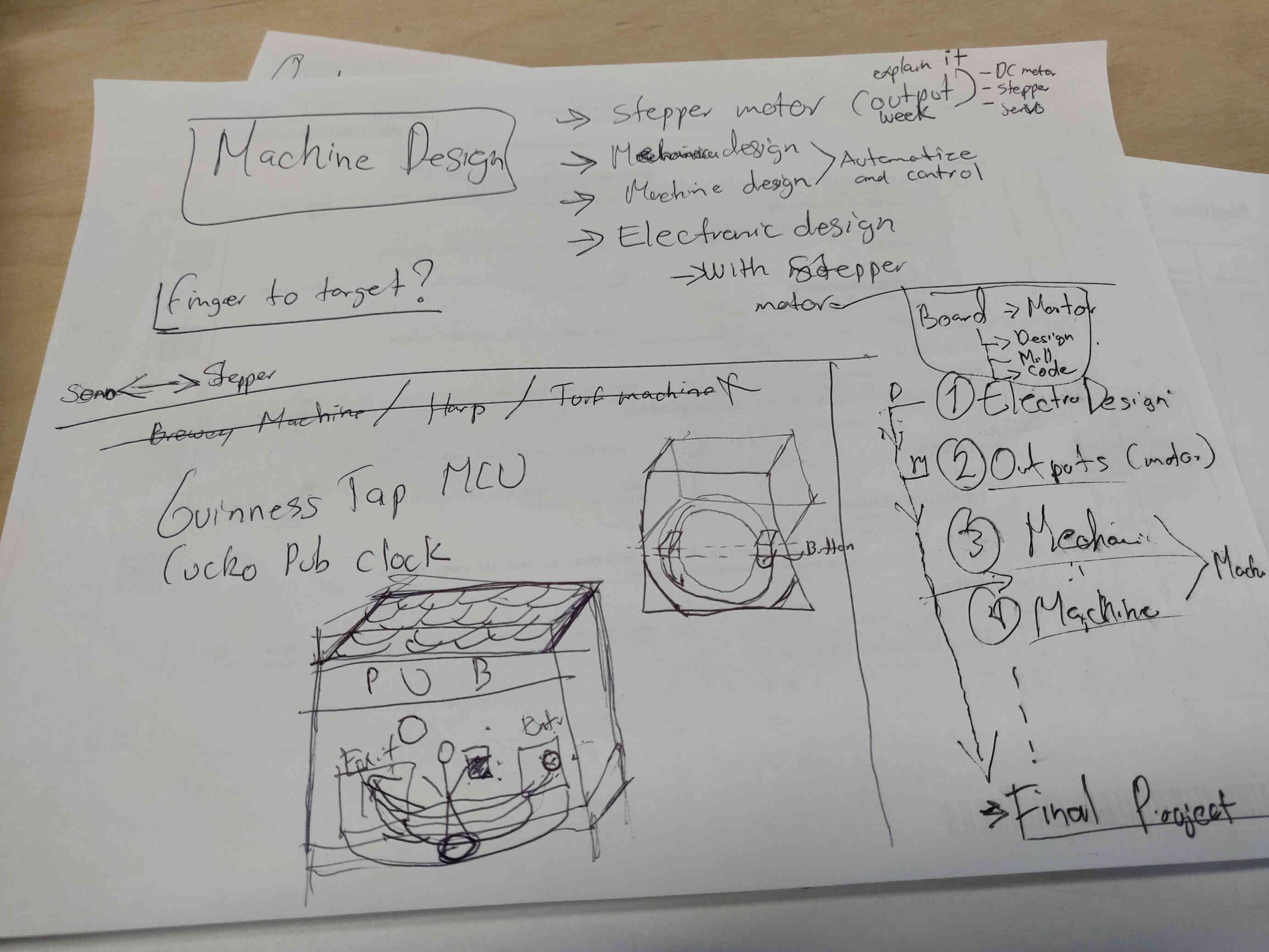
    We discussed possibilities for machine designs that are representative of Irish culture. After some discussion, we took a look on Google for famous Irish machinery. The results that followed were classically stereotypical:

  • Turf Agricultural Machinery: I begged Oscar that we would not do anything related to turf - and he agreed.
  • Sports Inventions:Though football, rugby and hurling are major influences in Irish culture, I myself am not a sports-enjoyer, so I wasn’t interested in making a project about it.
  • Guinness Brewery Machinery: Another expected result, I wasn’t keen on pushing the drinking narrative of Irish culture, but undeniably it brought up some interesting design possibilities.

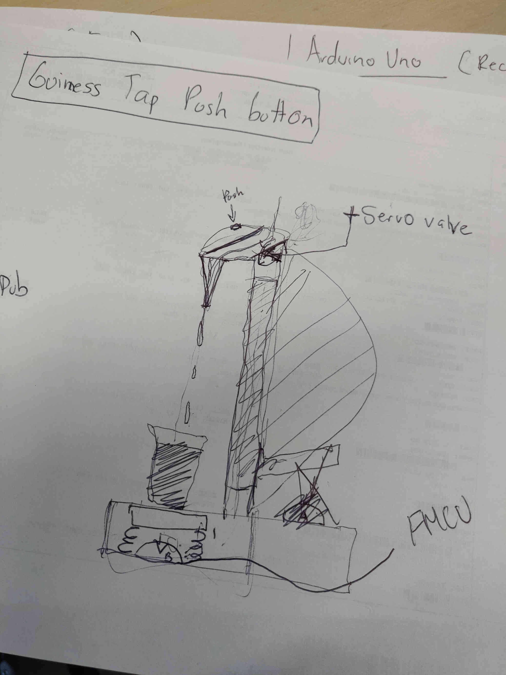
  • We were considering designing a type of lever, valve and pressure plate design where filling a pint glass will ‘turn on’ our machine, or a Guinness Pressure Tap with a Harp woodcut design and spent some time breaking down what we would need. We researched the code needed along with mechanical / automation designs related to pressure taps and found that there was certainly a possibility that we could make something in this nature with ease, but it would require us acquiring some plumbing equipment and tools along with researching pump pressures, etc. We weren’t 100% on this concept, so we looked into other possibilities.

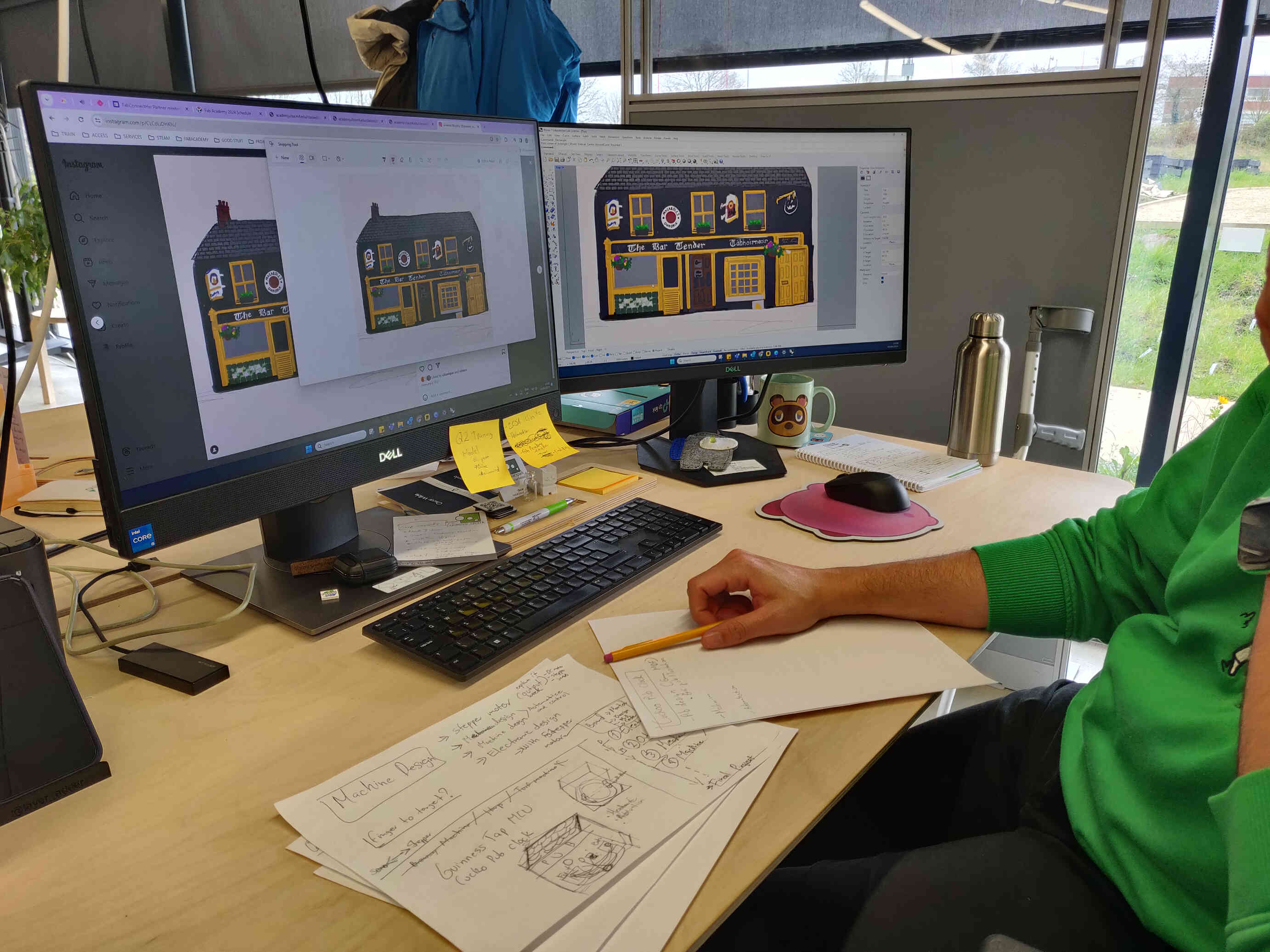
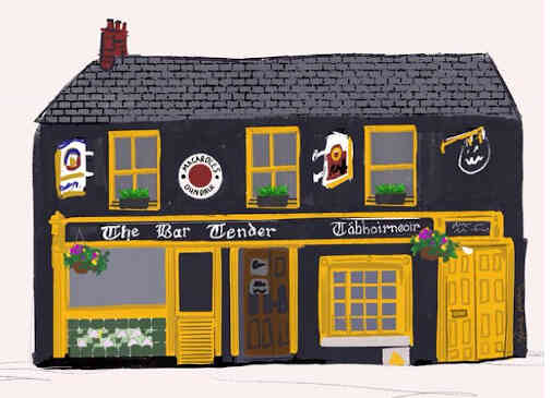
    I’ve been fascinated with some of the cuckoo designs made by other Fab Academy students and was interested in designing one myself in an interesting way. Also keeping in mind how relevant Irish print design culture is, I was inspired by a piece made by a colleague of ours, local irish printmaster ‘Grainne Murphy’ and considered implementing her work into our design. Grainne would print designs she made of Dundalk architecture and one in particular caught my eye. One of ‘The Bartender’, a distinguishable pub found in the center of Dundalk Town, Co. Louth, Ireland.
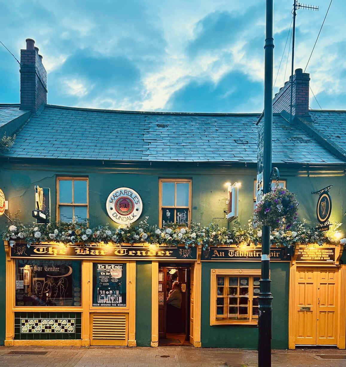


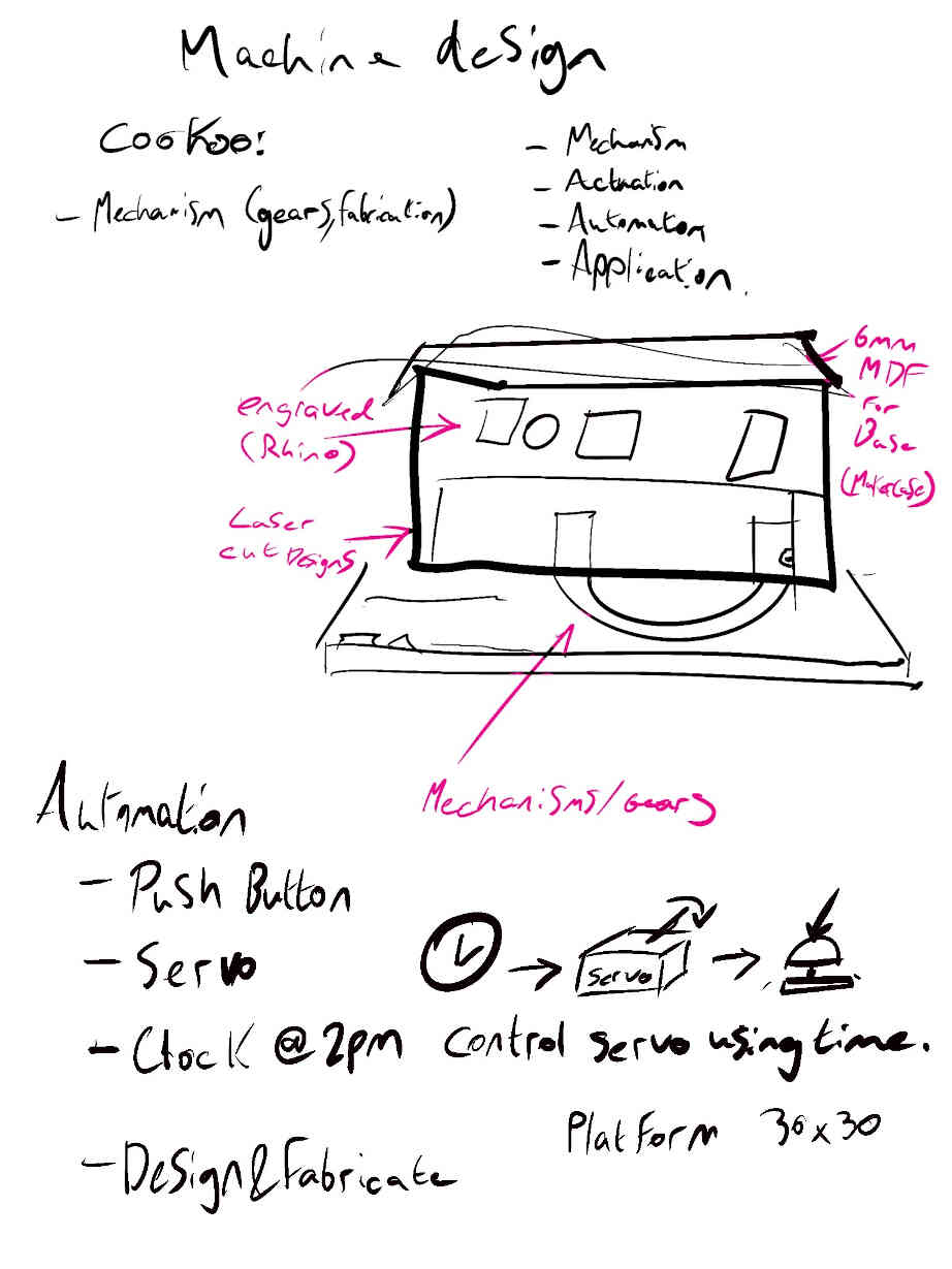
    I pitched that we could recreate the pub based on her design using either 3D printing or laser cutting techniques, and design a rotary wheel that has a character with a beer glass coming out. I know I said I wasn’t keen on doing anything stereotypical but I was really into the design process and possibilities, so I pushed it anyway. Oscar also suggested that we set the machine to a timer or dial, then once activated could have the little guy push a button as he comes out, which would activate an online link from Enterprise Fablab to every other Fablab node in Fab Academy through the FMCU Network. We were happy with this concept so we concluded the brainstorming process and broke down the mechanics, parts, circuitry, designs and code needed.


    Oscar said he would focus on the programming / electronic side of things while I focus on the design, cutting and assembling. Then we would come together to implement the design and functionality of the machine.

    I stuck around Oscar as I started working on the design and he started researching the mechanics and code so I could get an understanding of his side of the process. We found a very cool website named Gear Generator which allows you to design your gears with a visual representation to the side and download the design files. We still needed to design the gears we needed for the assignments but this site would be a great reference point. In case you’re interested, Gear Generator costs money to download the designs but a free alternative is a site named STLgears.com.

    ____________


    Concept Designing


    Maker Case Design Process:
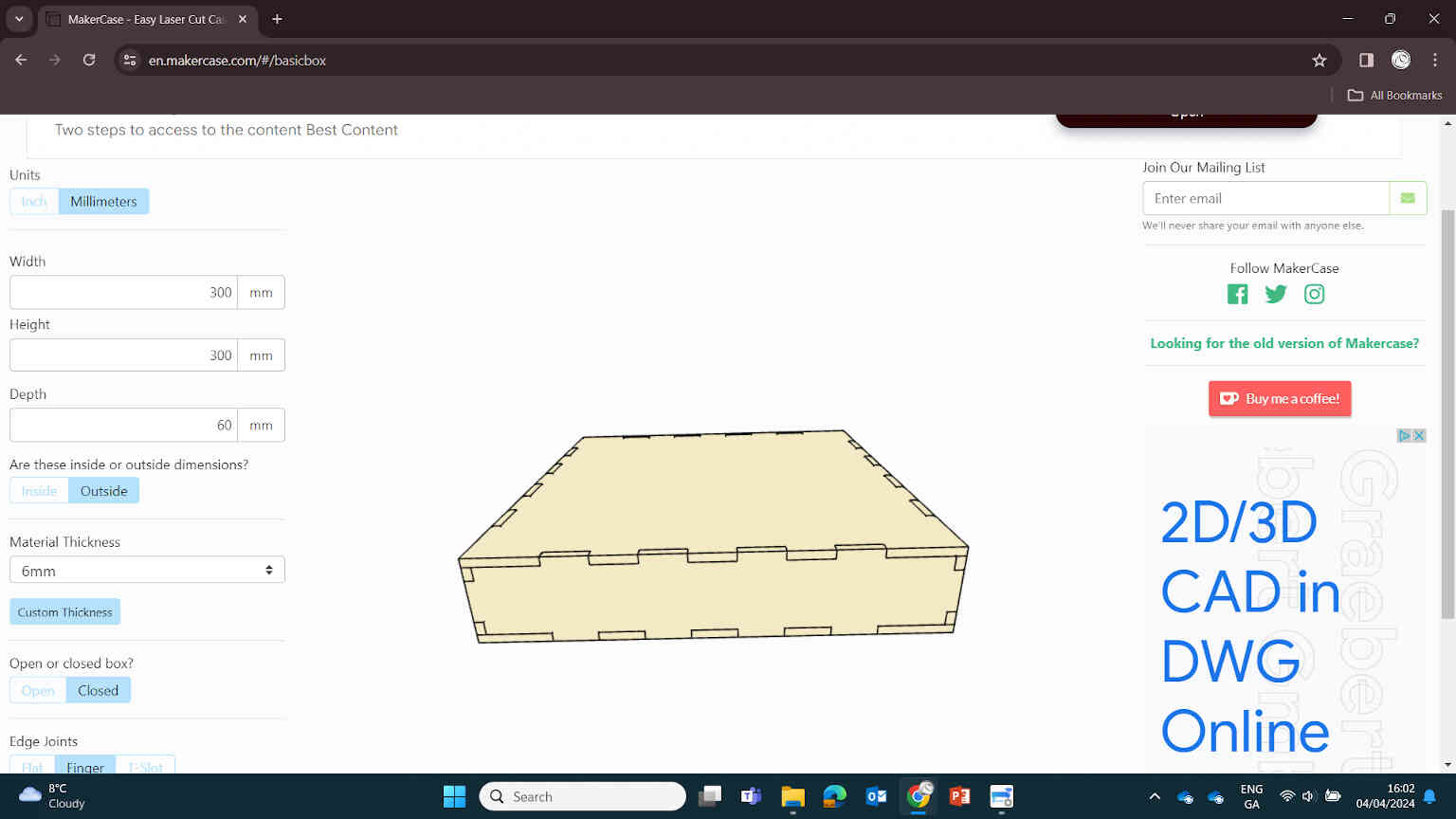


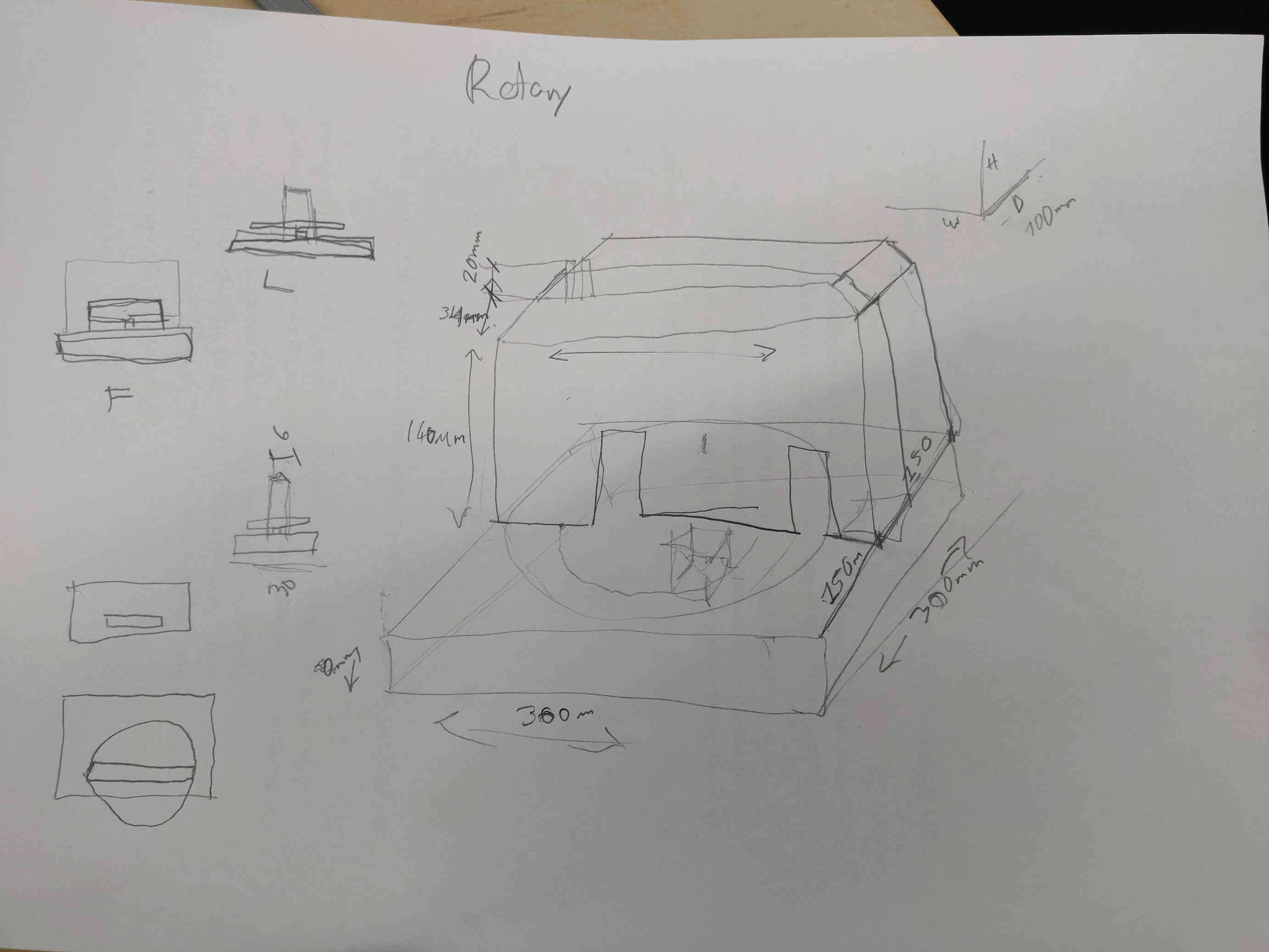
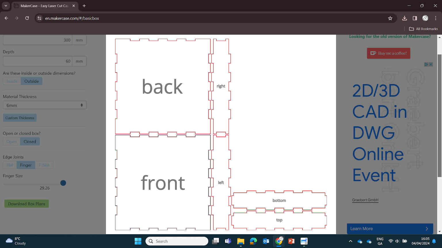
    Before starting with the Rhino design, it was important that we drew some measurements to get the correct sizing of both the Bartender Pub itself, and the base that it sits on which would contain the electronics needed for the rotary wheel and the mechanisms needed for connecting to other fablabs. I would then take these measurements and input them into MakerCase.com to download a template dxf file, which can then be edited in Rhino 2D CAD software. This is what I settled on:
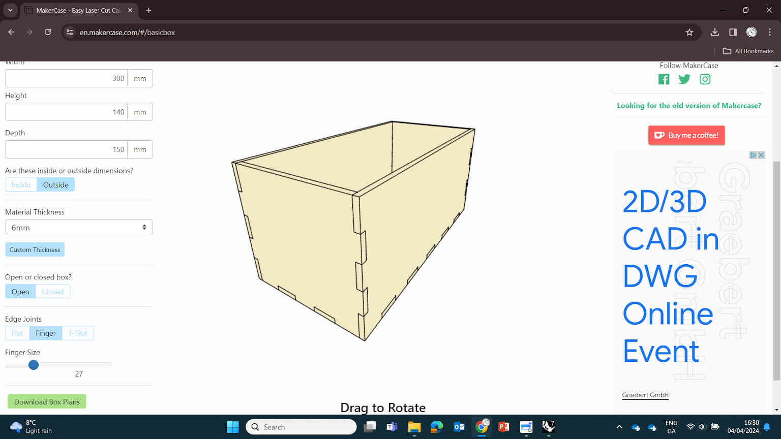
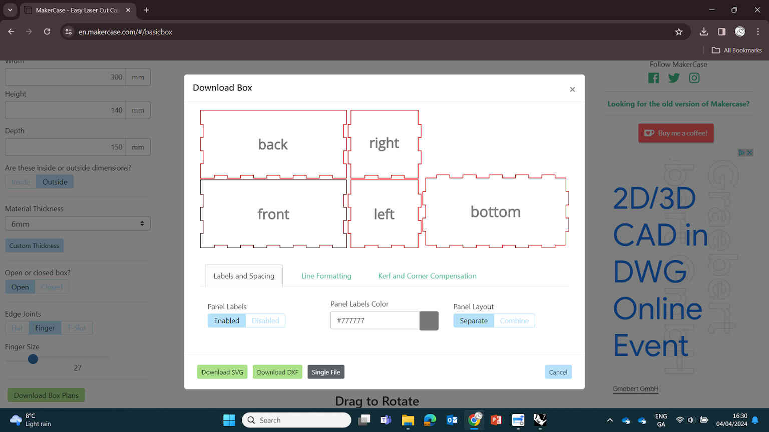

    Measurements for Makerspace:

  • 6mm MDF Base (Closed): Height = 60mm, Width = 300mm, Depth = 300mm.
  • 6mm MDF Building (Open): Height = 140mm, Width = 300mm, Depth = 150mm.

  • Sheet Measurements to hold extension cuts:

  • 3mm MDF Design Extensions: Height = 150mm, Width = 300mm, Depth = 3mm.

  • ____________


    Editing Design in Rhino


    (^ Print Design by Grainne Murphy)

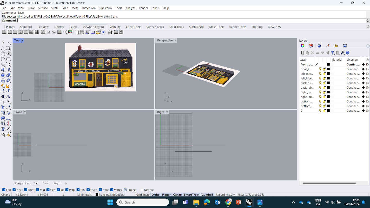
    Taking a screen grab of Grainne Murphy’s print of the Bartender found @Grainne’s Instagram, I used it as a reference for my 2D designs in Rhino. I opened the Bartender Pub template dxf file and imported Grainne Murphy’s image and scaled it to our measurements. I didn’t need to change much here, except using the Polyline tool to edit in the cuts on the front panel for where the doors are (where the little man will be coming through on the rotary wheel).
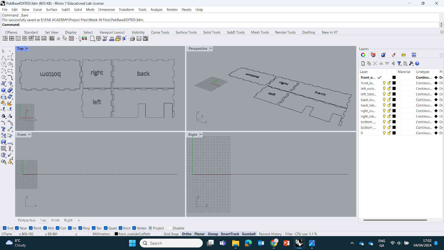

    As for the design extensions, I made a duplicate of the Bartender Pub dxf file and removed everything except for the front panel. Within this panel I traced over all the design elements that I would need to cut out. As per Oscar’s instructions, I didn’t go too crazy with the design due to time constraints but I did focus on what makes The Bartender distinguishable from other pubs - one of which being the bold yellow and black colour scheme, but the colour is something I may do after the assignment is complete.
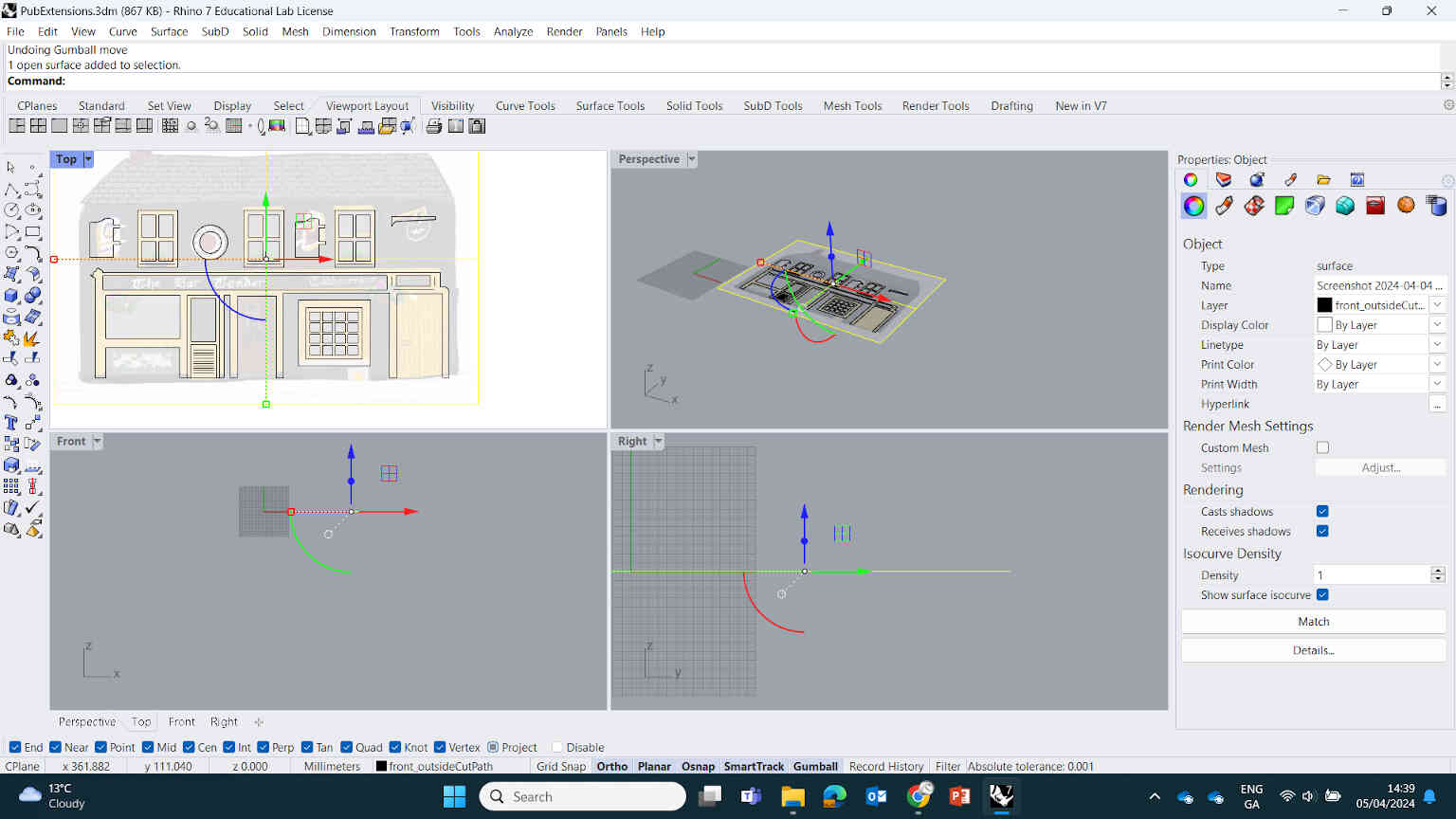
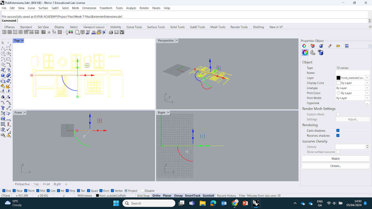

    When the time comes for colouring, I’ll be using a white primer paint then an airbrush for overall colour. For now, I just focused on getting the measurement correct for the doors, windows, signs and panels. Once done, I exported the 3 designs as dxf files labeled 1-Base, 2-Building, 3-extensions and brought them into Coral Paint which connects to our laser cut machine.

    ____________


    Laser Cutting and Assembly

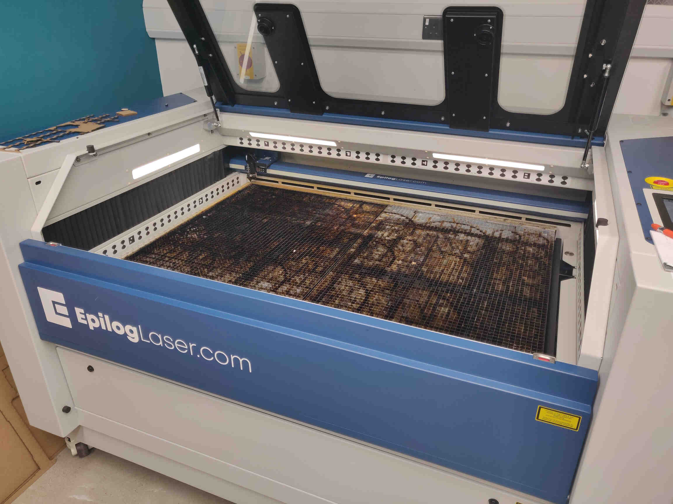
    Initially considering the Shopbot for the cutting process, we determined a laser cutter would be what we needed for our product. So instead we brought our designs into Corel Paint which was connected to the fablab’s EpilogLaser laser cut machine. By importing our files into Corel Paint, we can then hit
    Print which would then bring us to Epilog’s cutting software.
    11

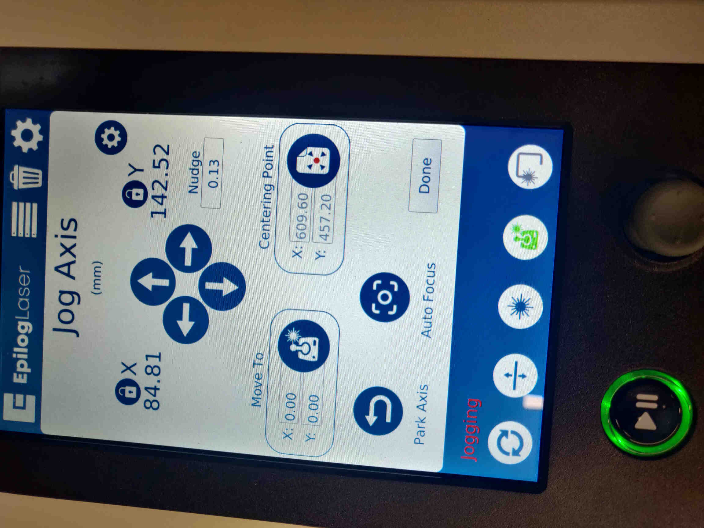
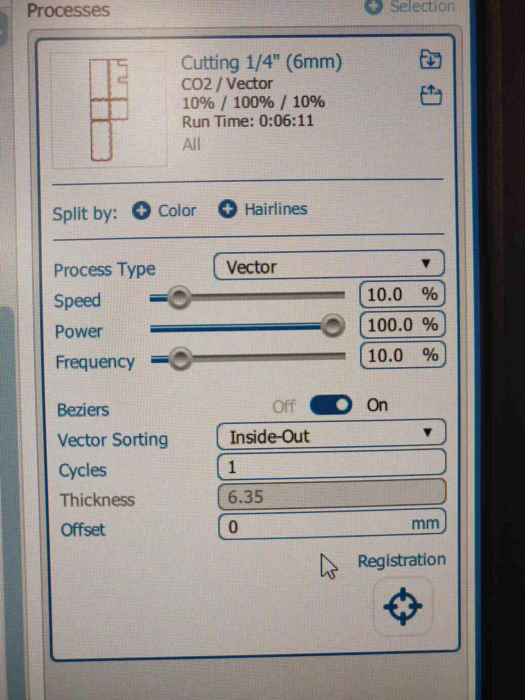
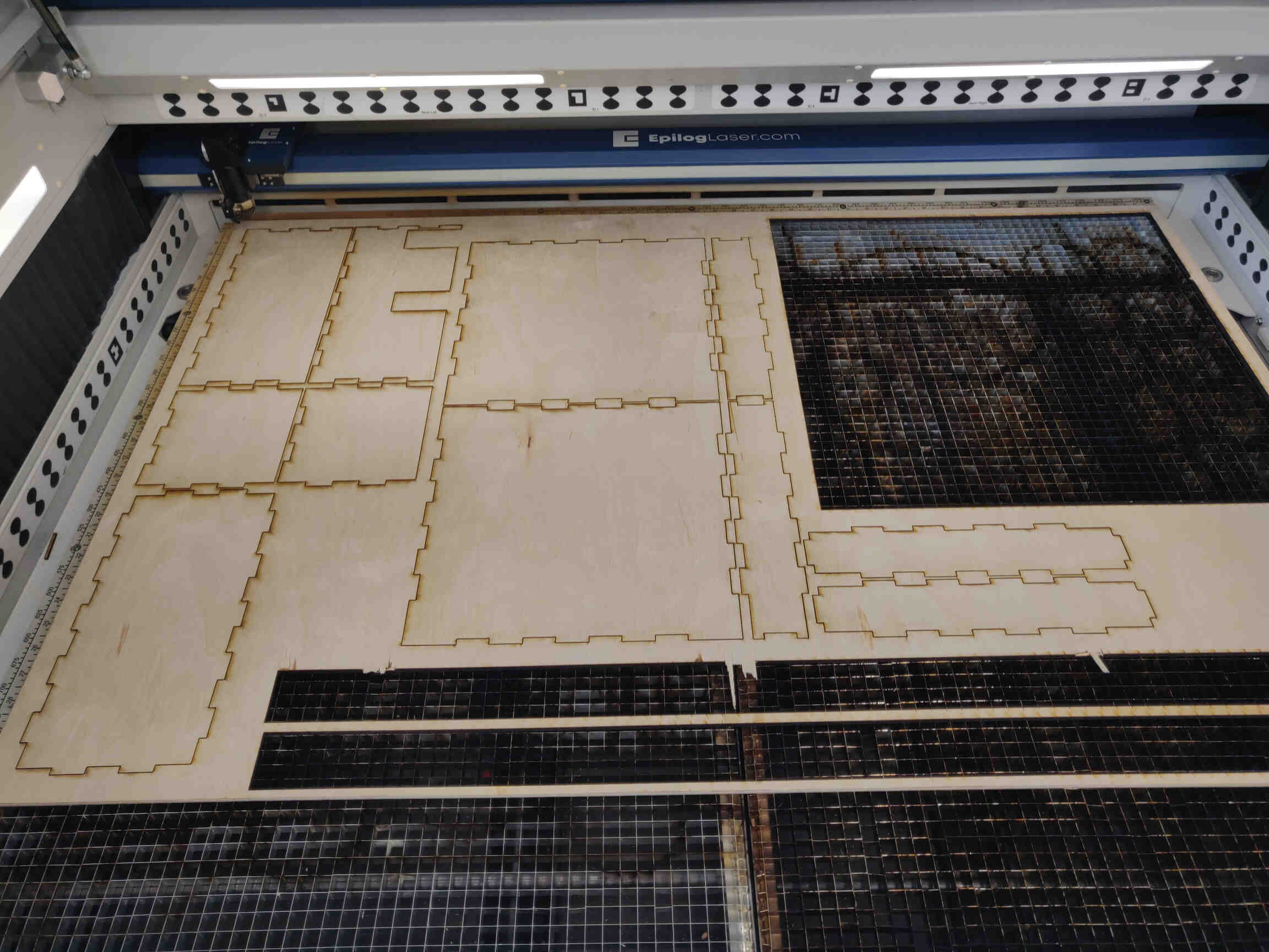
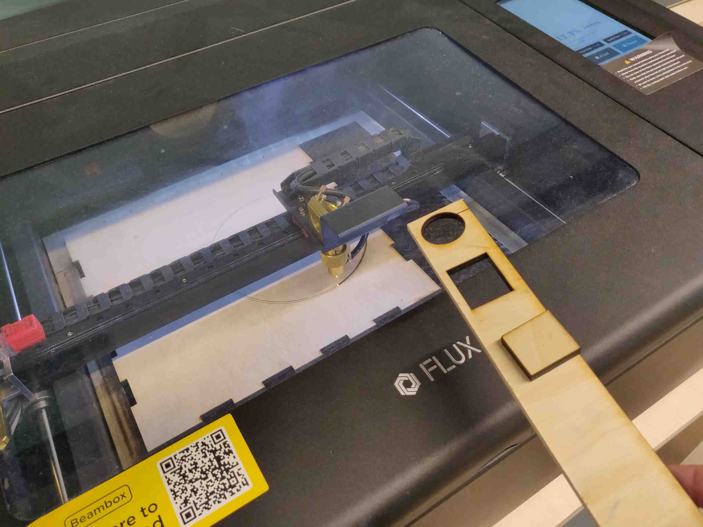
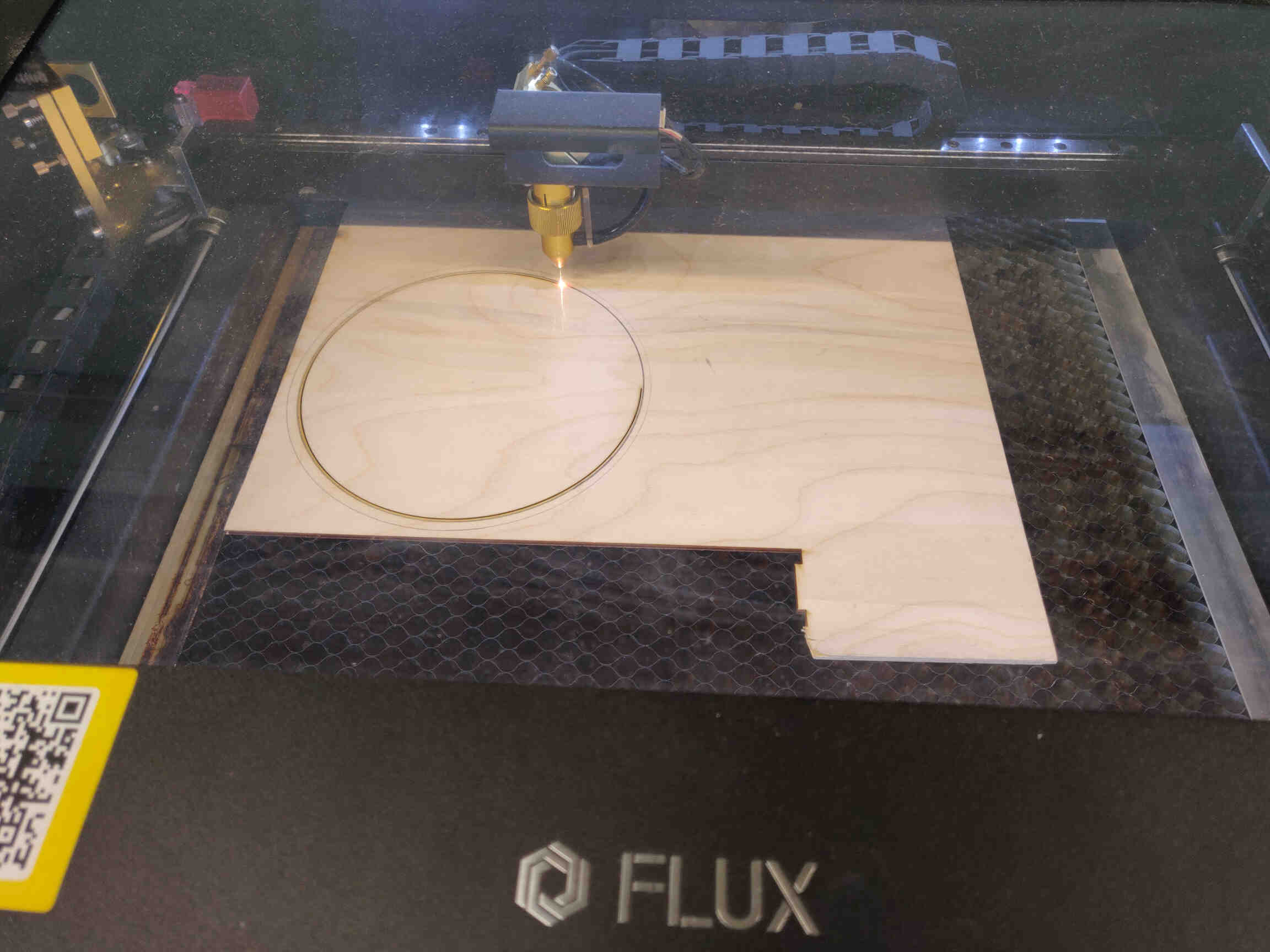
    We opened up the Laser cut machine and placed a sheet of 3mm MDF inside, then went back to the cutting software and used the Camera tool to give us a digital view of the inside. With this, we were able to nest and position our designs correctly. Using the panel on the machine, I was able to calibrate the distance between the laser and the sheet of MDF by using the Jog Axis controls and hitting ‘Auto Focus’. In the cutting software, at the panel called ‘Processes’ we were able to import a preset for 3mm wood cutting.

    Presets for 3mm and 6mm Wood Laser Cutting
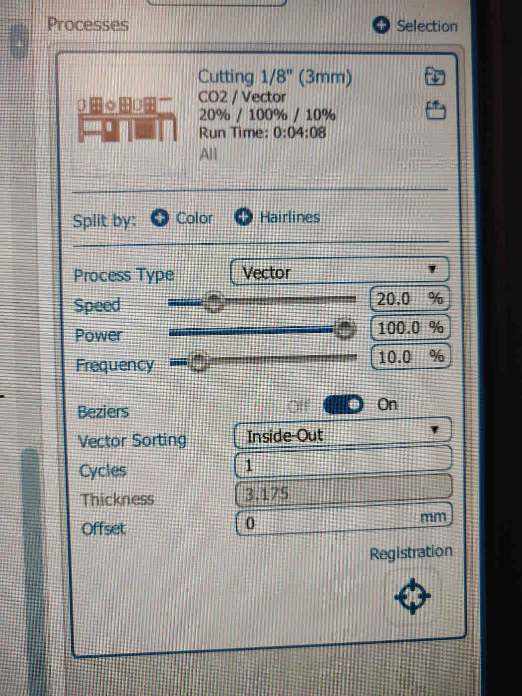
  • 3mm Woodcut: Speed = 20%, Power = 100%, Frequency = 10%
  • 6mm Woodcut: Speed = 10%, Power = 100%, Frequency = 10%

  • 11 11 11

    After the 3mm design extensions were complete, we placed a used sheet of 6mm MDF inside the machine and repeated the process for the Base and Pub cuts. We were able to nest both file designs perfectly into 1 previously used sheet of 6mm MDF.
    NOTE: The machine needs to be calibrated again once changing material.
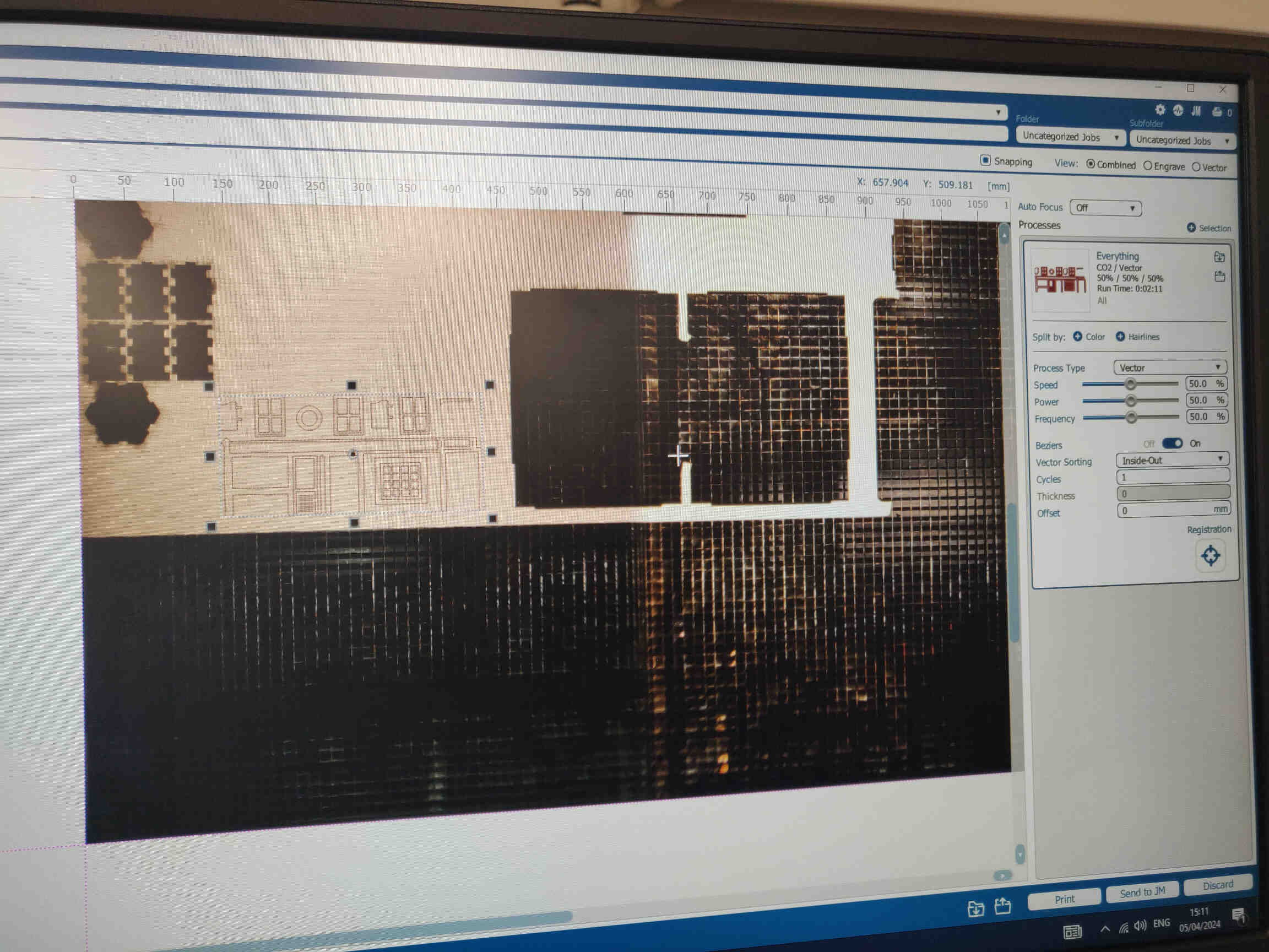
    11 11


    ____________


    Assembly Process

    Once the laser cut was finished, I removed the sheets of MDF, placed them on the floor and knocked the designs and panels out of the sheet and placed them on to a cutting mat to position them correctly. Some of the panels still had some wood splintering out, so I used a flat chisel and hammer to cut out any extending pieces. Then I sanded the sharp edges down - though I could have done some more sanding down to ease the assembly process.
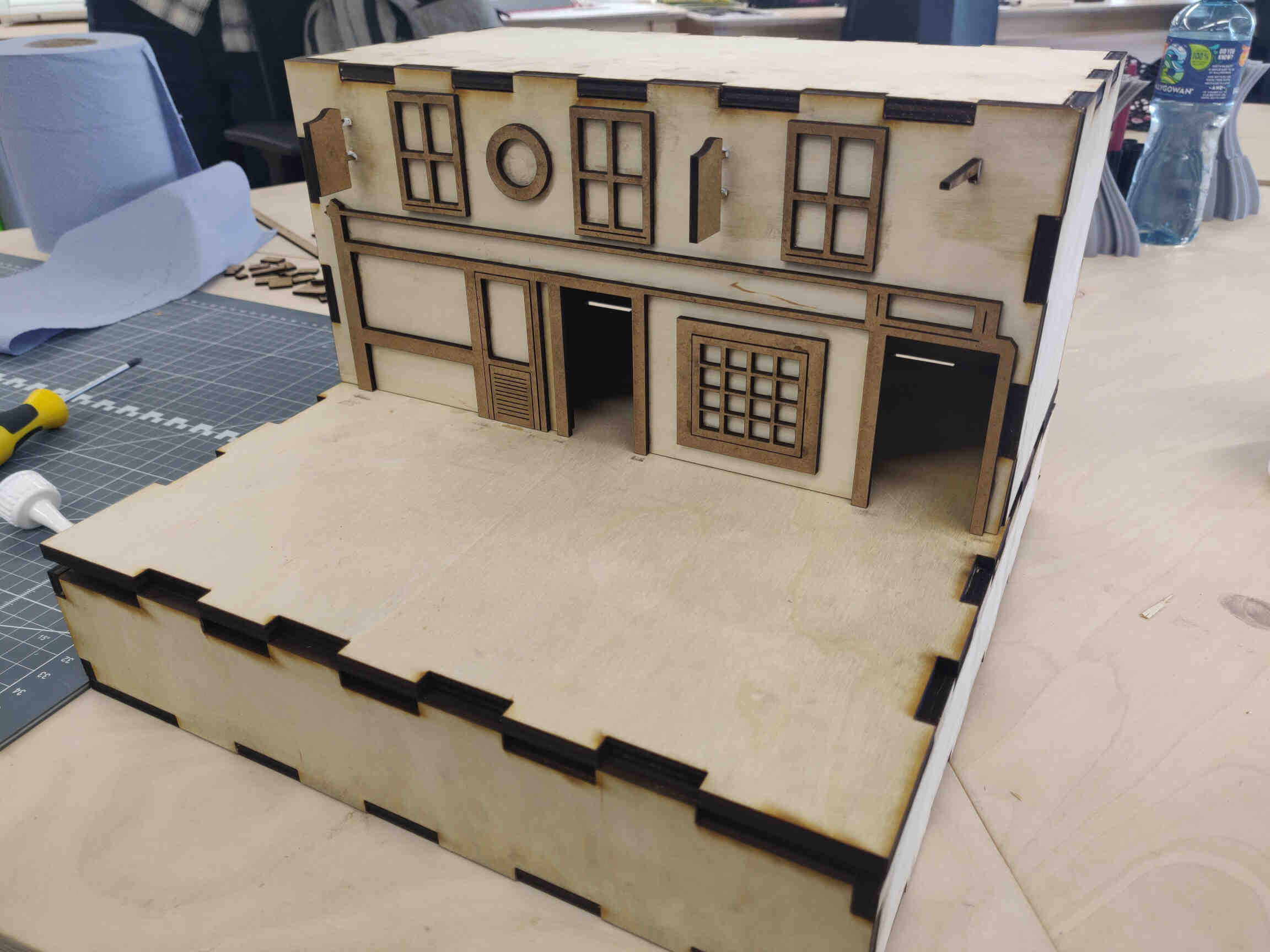
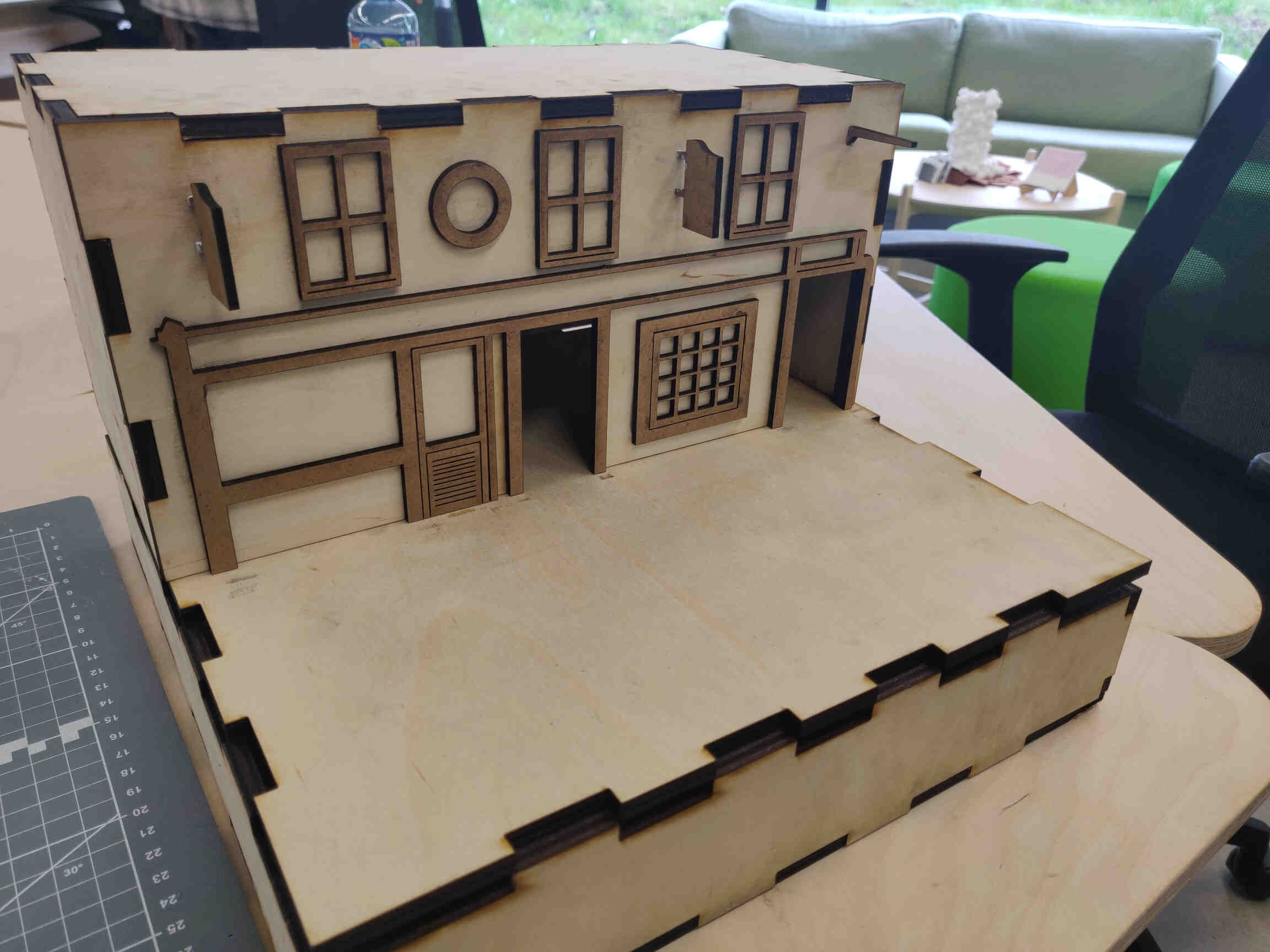
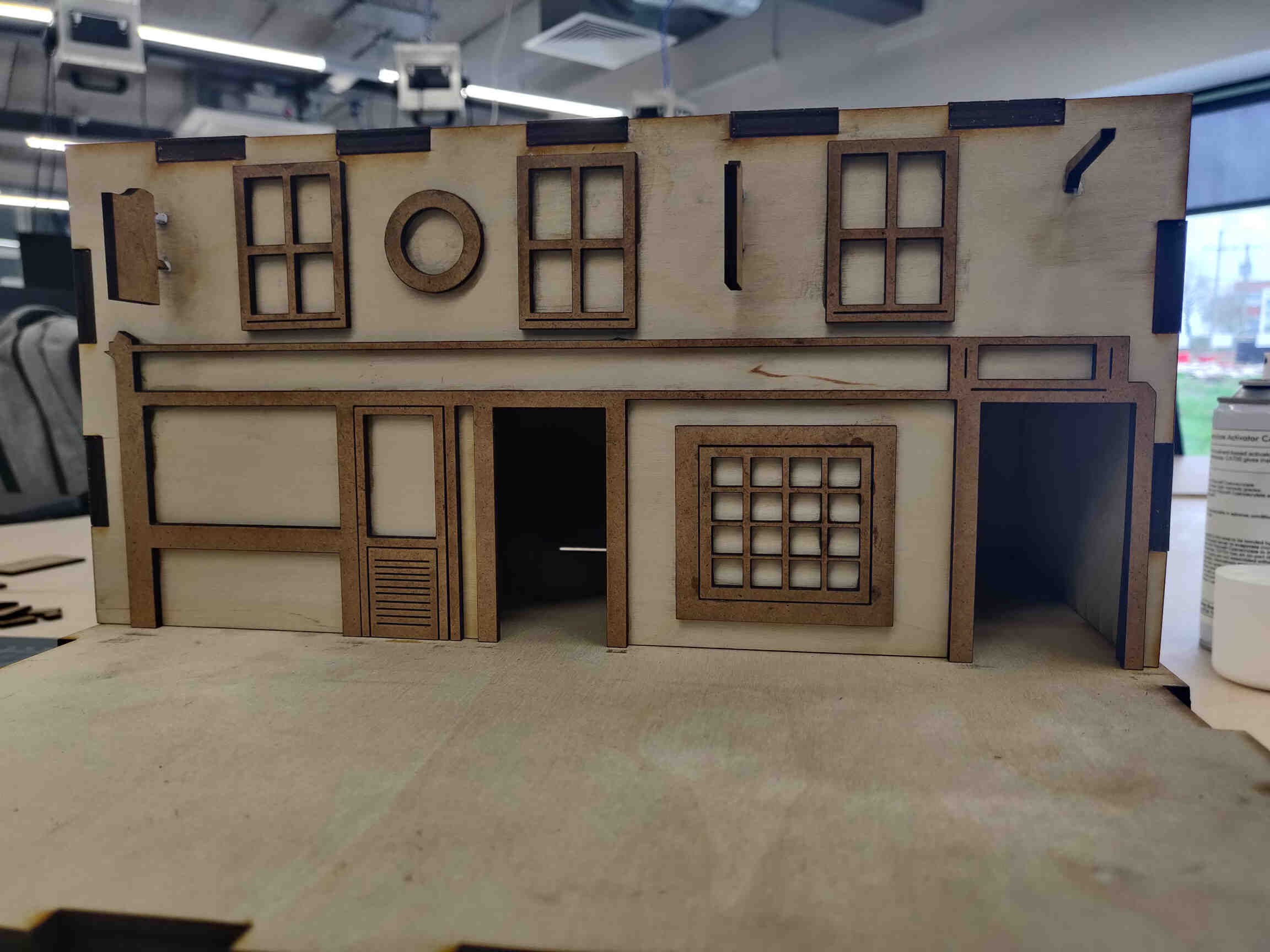


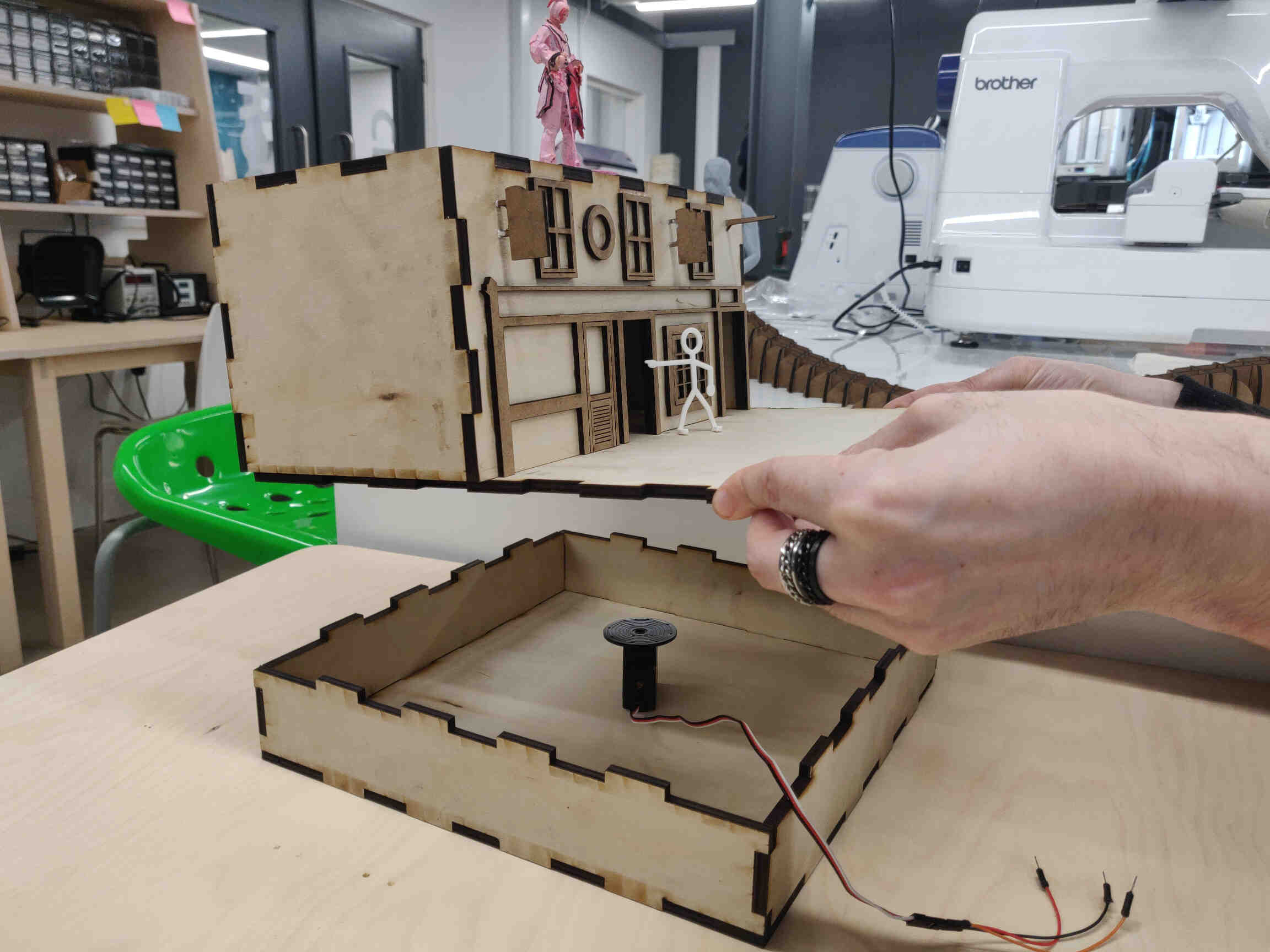
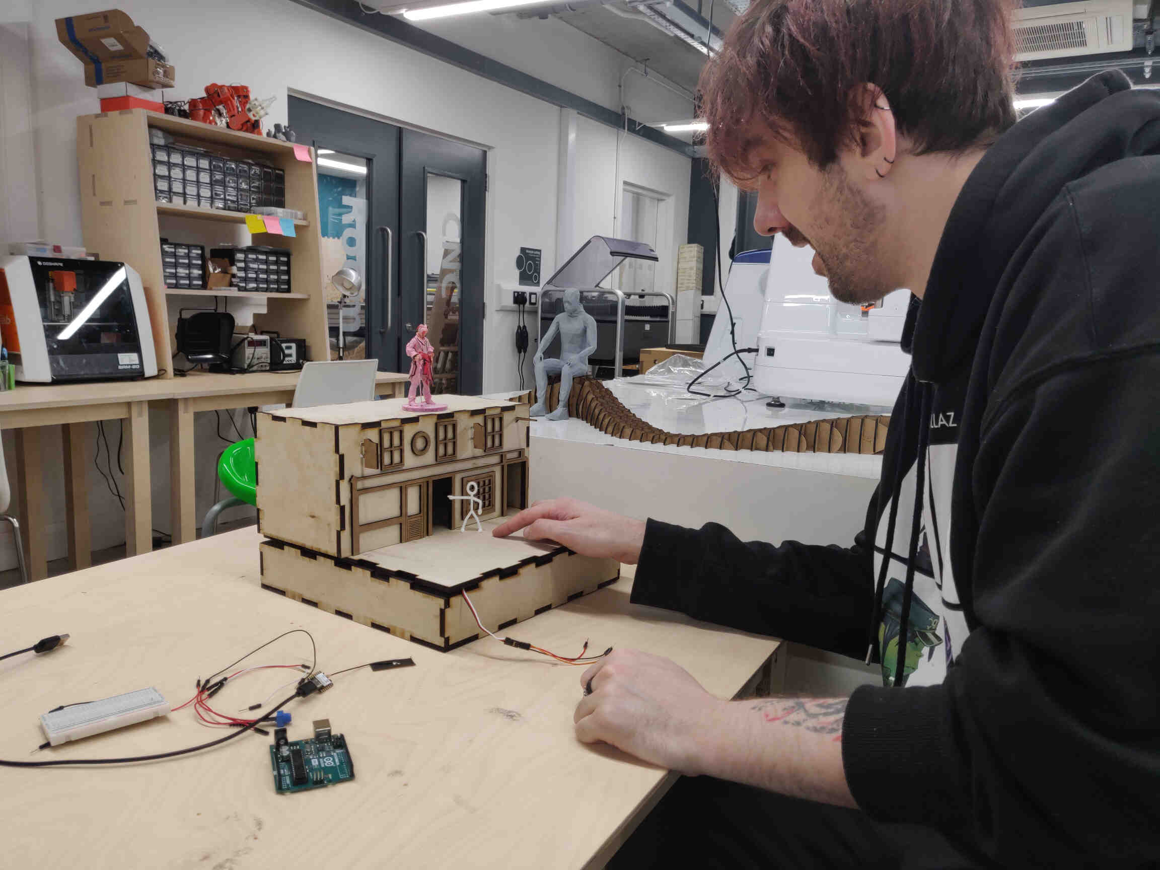
    As our pieces were cut out with a laser, we didn’t need to add dogbones but the finger joints were still pretty tight. 5 minutes with a hammer later and the Base and Bartender Pub were assembled. For machine building, we were told to avoid glue but focus on fasteners - however I used gorilla glue to stick on the Pub Extensions as they were just extra designs that don’t affect / improve the mechanics or function of the design - they only make the Pub distinguishable. As I mentioned before, I may leave the colouring until after the assignment as I need to be aware of time management.

    ____________


    Cutting for Assembly


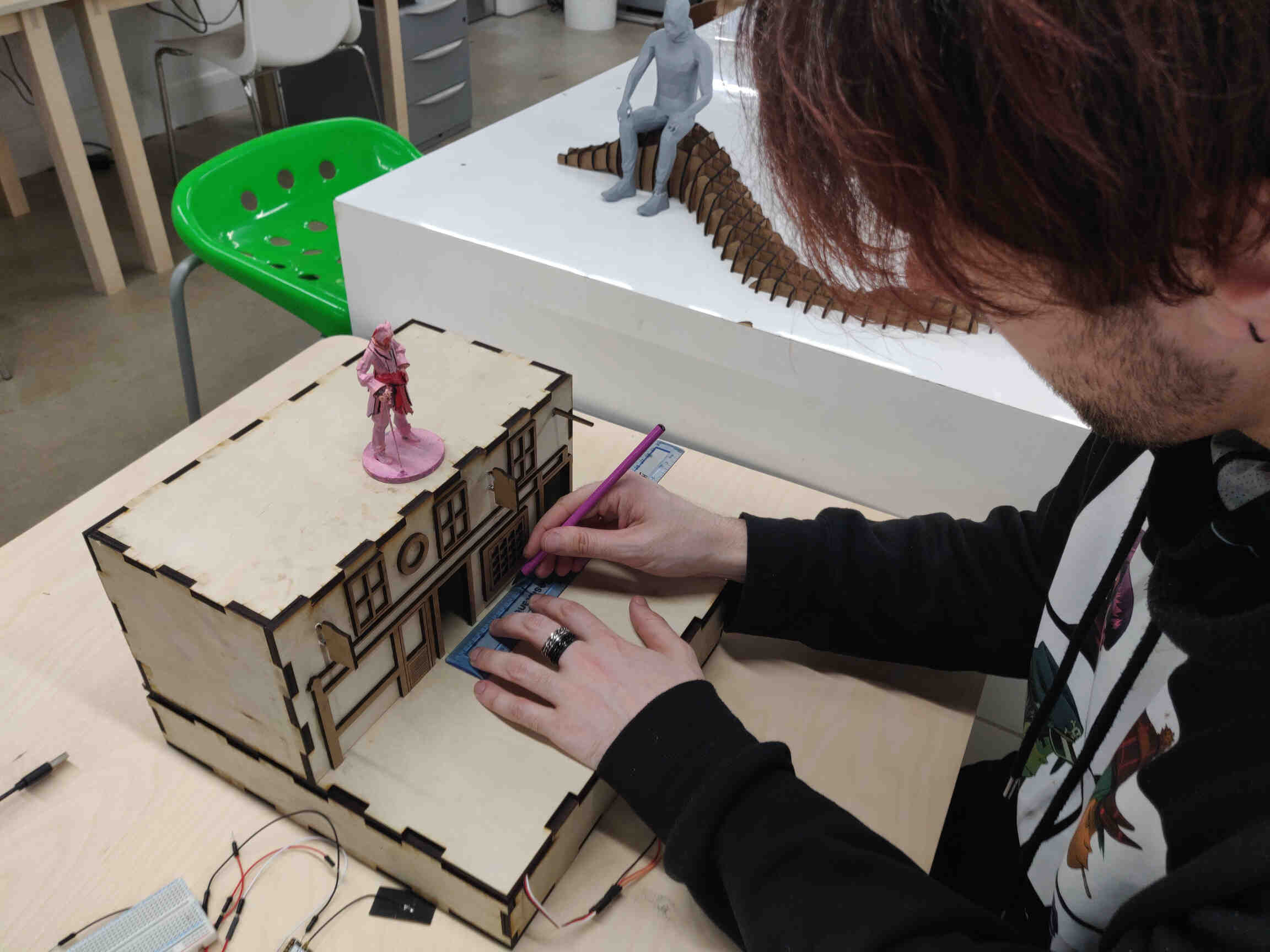
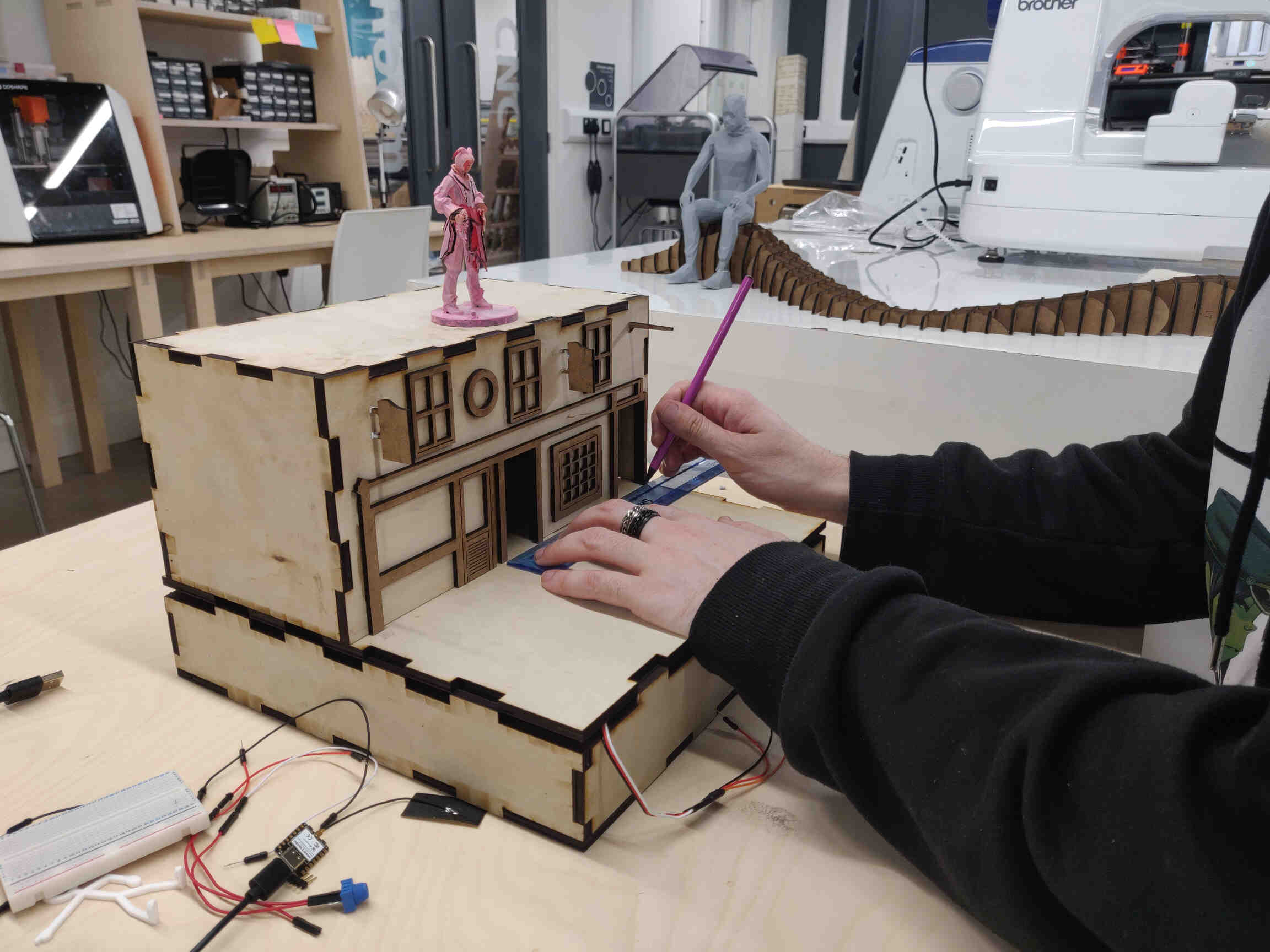
    Rotary Wheel Base: We needed to cut a hole in the base for the rotary wheel to slot in underneath the Bartender Pub. So I took the top panel of the base and using a makeshift compass I made the necessary measurements and brought it to our laser cutter to laser cut the hole we needed.
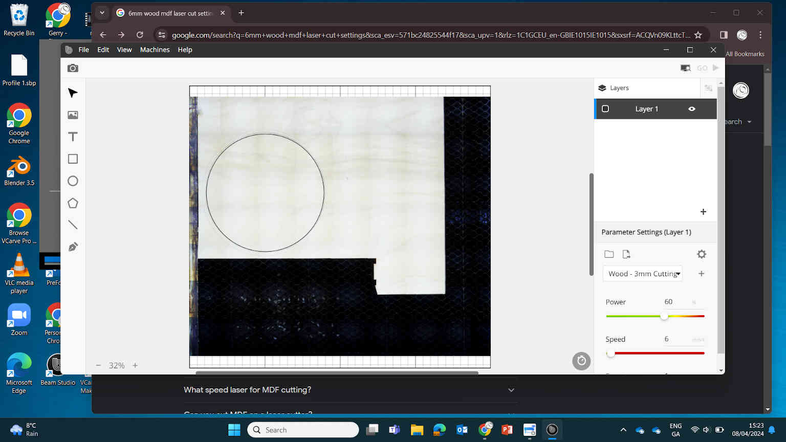
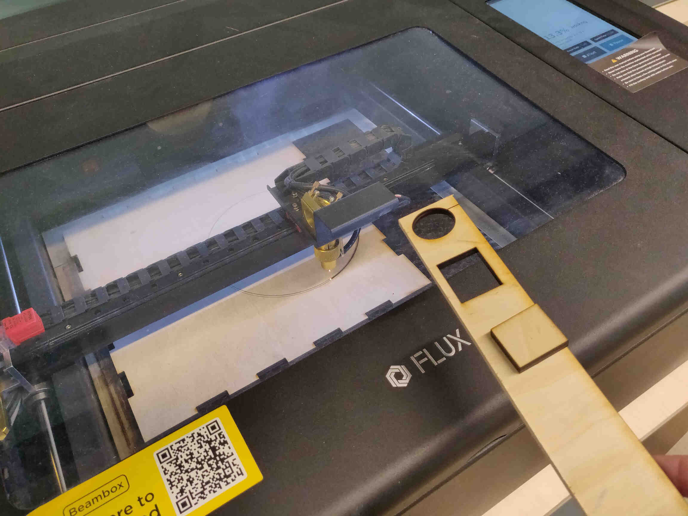
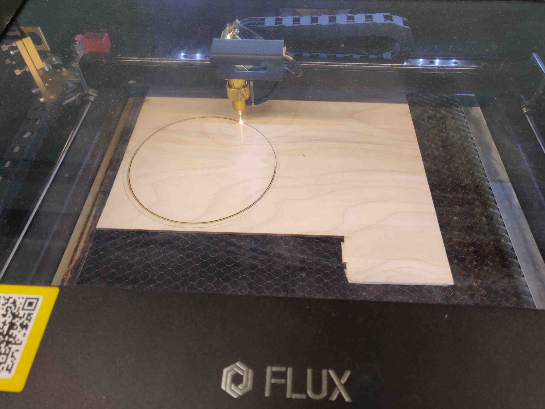
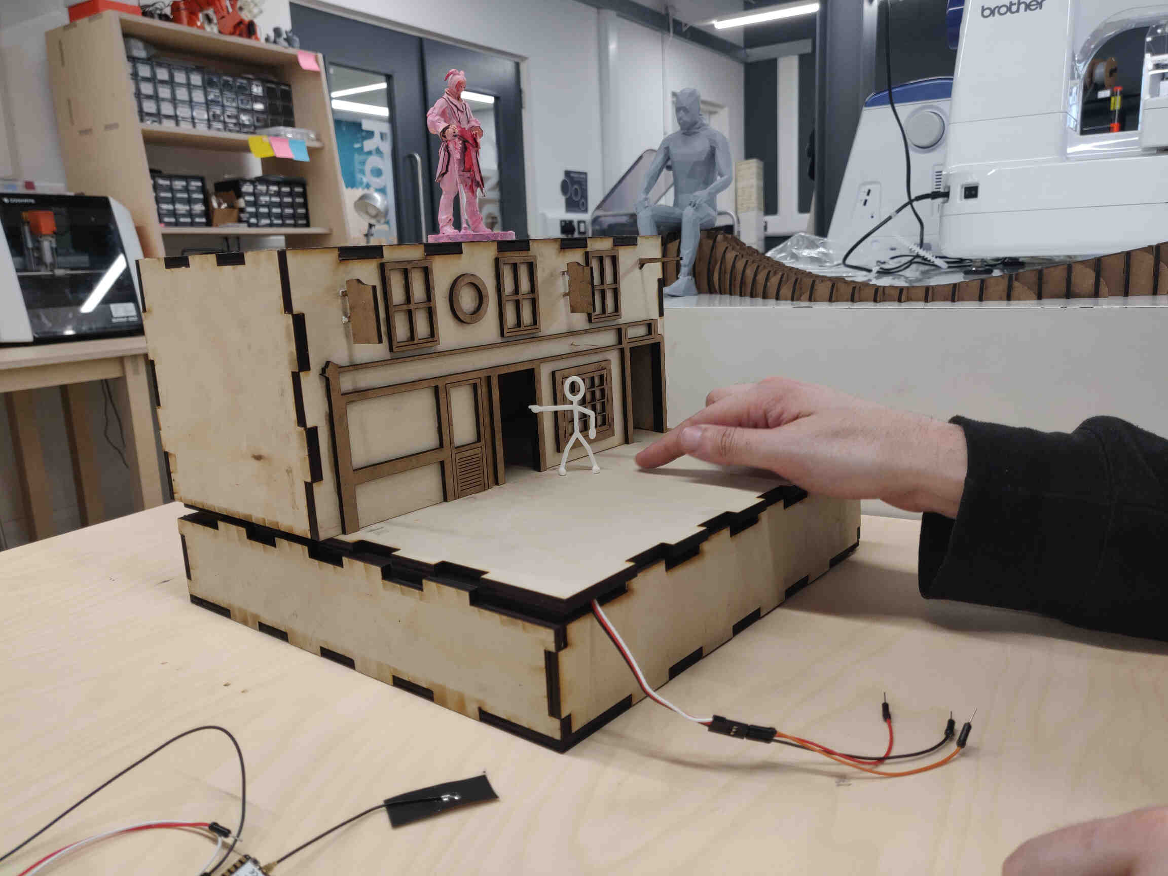
    Then I got a 3mm piece of plywood and laser cut a hole 3mm shorter in diameter for clearance. Placing this rotary board on top of our servo wheel, and placing a 3D printed stick figure on top, we were able to test out the mechanics of our machine - it worked perfectly as you can see from the video below.
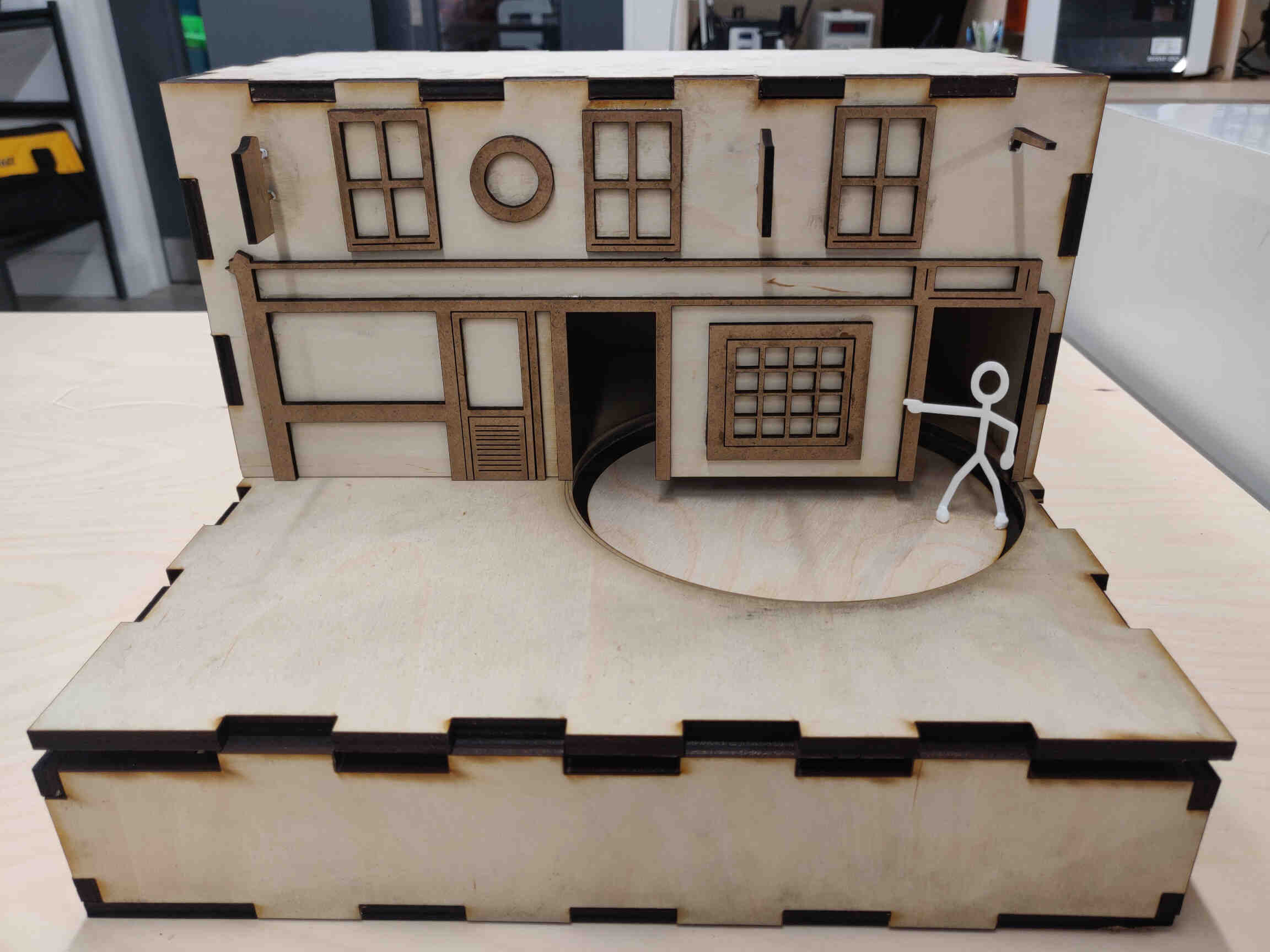
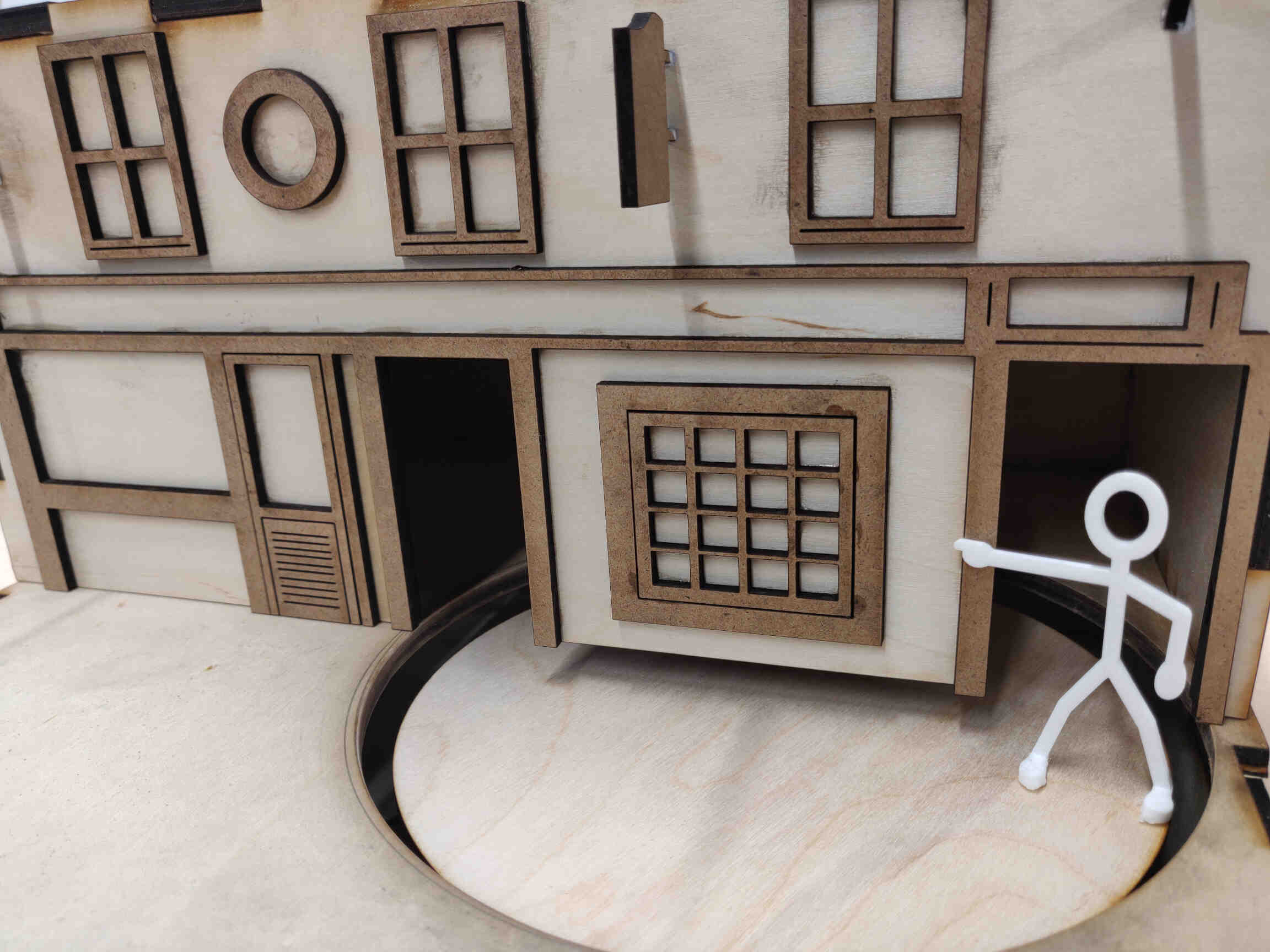

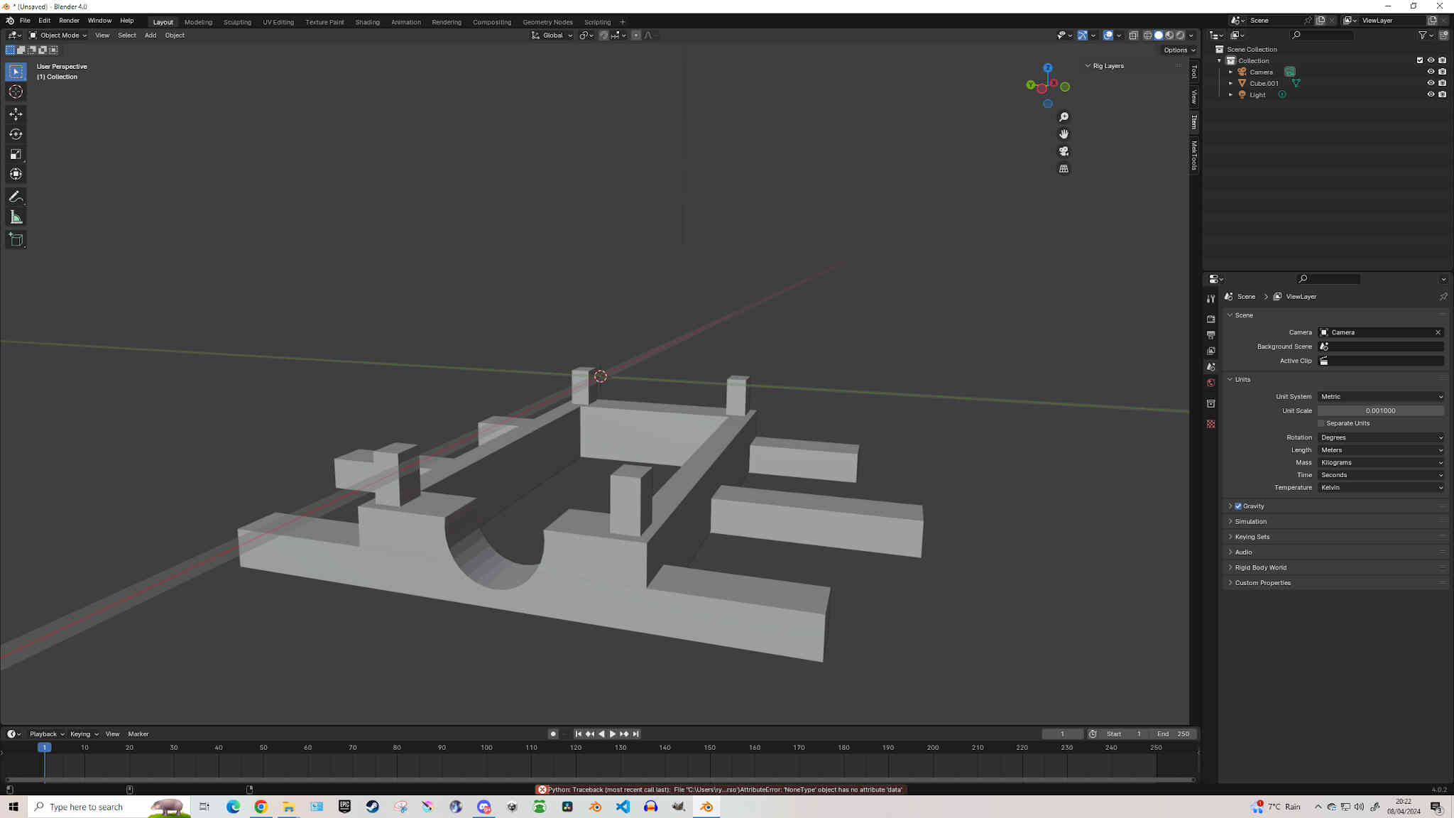
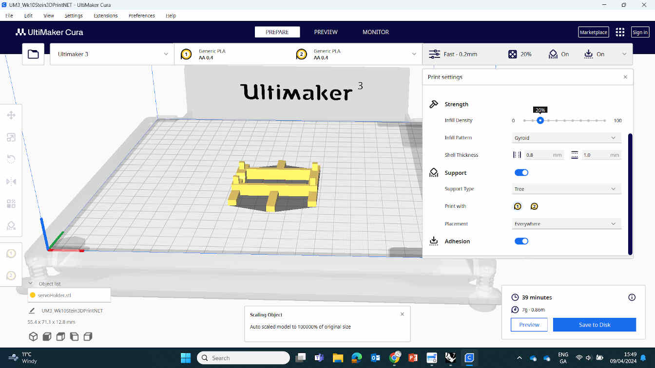
    We then needed to make some cuts for the wiring, potentiometer and servo placement. We drilled a hole for the potentiometer and I designed a holder for the servo motor in Blender after taking some measurements, as well as a sign on Inkscape for the machine instructions - which we later engraved onto the left side panel.

    ____________


    Printing the Little Man

    For the Little man design, I used the custom character creator in the video game MMO Final Fantasy XIV and imported the character design into blender, where I posed him correctly and designed a Stein Pint Glass in his hand and used Prusaslicer to 3D print him out.
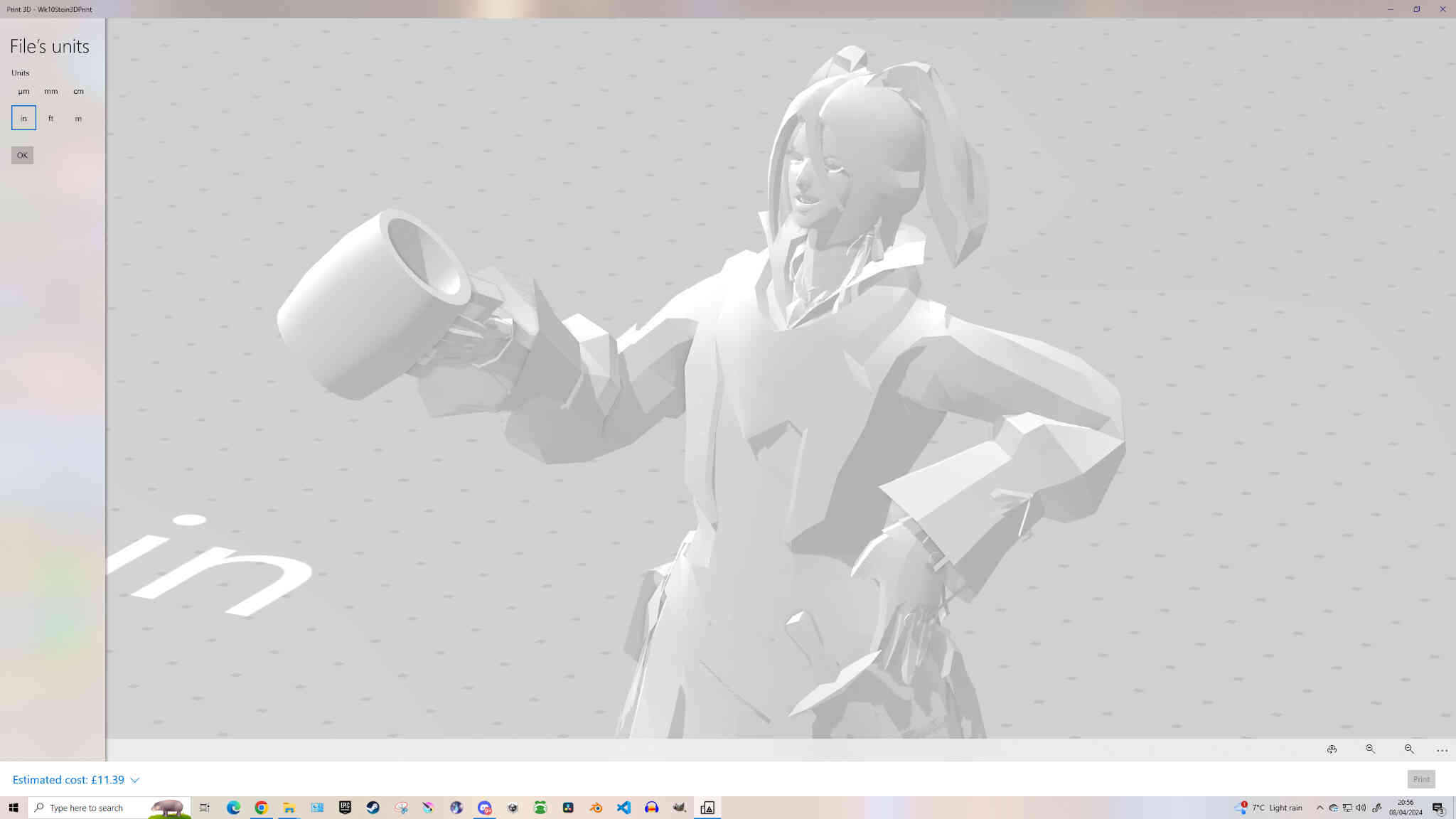
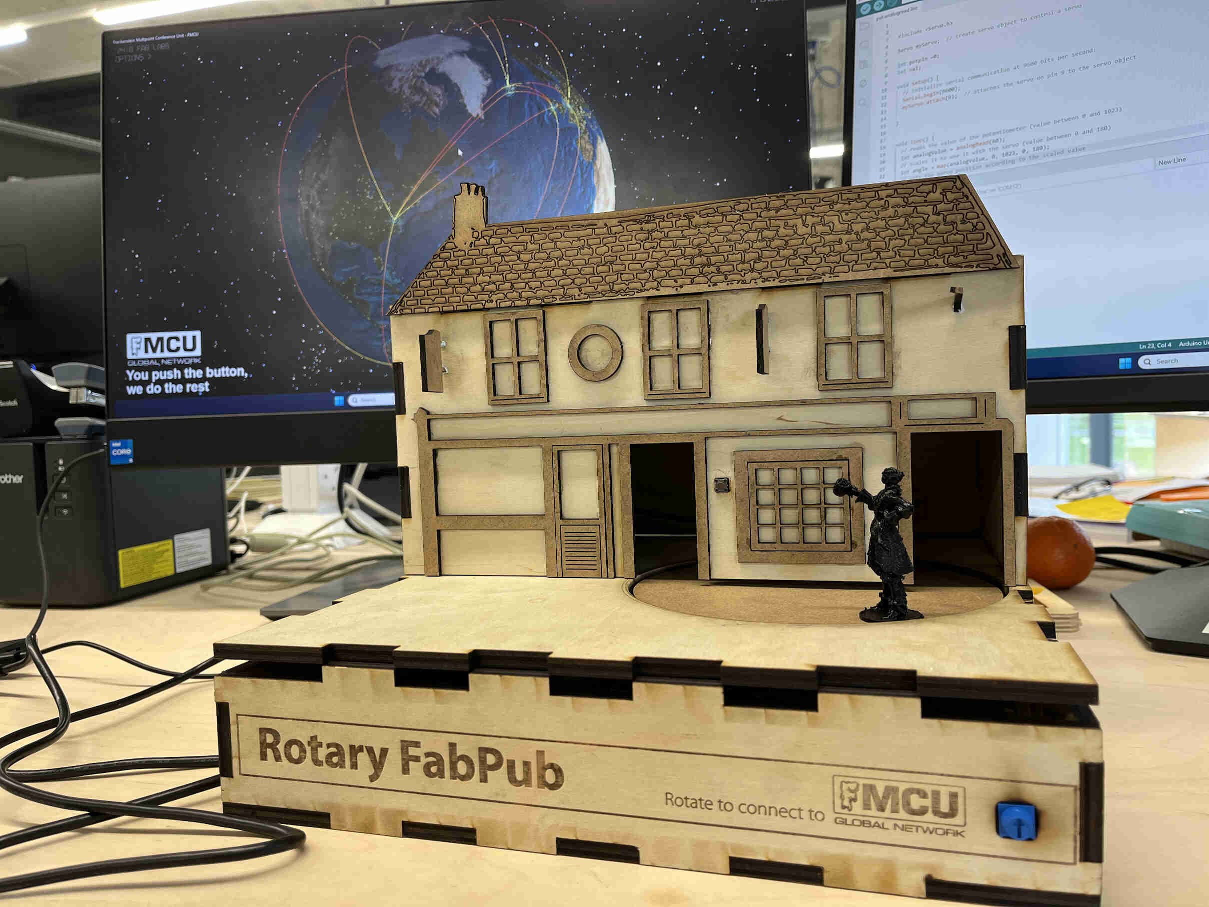


    ____________


    Electronics and Programming

    Checking in with Oscar, I saw that he had a servo motor working with a rotary wheel thanks to his electronic assembly and code implementation. These are the tutorials he used to get the motor running:
    Circuits DIY & Arduino Analog Read Serial.
    Group Assignment Link:

  • Click HERE to view Group Assignment Page!
  • Arduino Code for FMCU Wireless Connection and Servo Control using Potentiometer.

    (Code implemented by Oscar Diaz)

    #include < WiFi.h >
    #include "Adafruit_MQTT.h"
    #include "Adafruit_MQTT_Client.h"

    // The things you have to modify
    const char id[] = "2647"; // your fablabs.io lab id

    const int buttonPin = 10; // the number of the pushbutton pin GPIO 10 ESP32
    const int ledPin = 2; // the number of the LED pin Internal LED
    int buttonState = 0; // variable for reading the pushbutton status

    #define WLAN_SSID "Your_Wifi_SSID" // your wifi name
    #define WLAN_PASS "Your_Password" // your wifi password

    // MQTT Settings
    #define AIO_SERVER "fmcu.fablabs.io"
    // Using port 8883 for MQTTS
    #define AIO_SERVERPORT 1883
    // MQTT Account Configuration
    #define AIO_USERNAME "fmcu"
    #define AIO_KEY "Push 1 Button"

    // WiFiFlientSecure for SSL/TLS support
    WiFiClient client;

    // Setup the MQTT client class by passing in the WiFi client and MQTT server and login details.
    Adafruit_MQTT_Client mqtt(&client, AIO_SERVER, AIO_SERVERPORT, AIO_USERNAME, AIO_KEY);

    /****************************** Feeds ***************************************/

    // Setup a feed with the id for publishing.
    // Notice MQTT paths for AIO follow the form: /feeds/
    Adafruit_MQTT_Publish alive = Adafruit_MQTT_Publish(&mqtt, "fmcu/id");

    // letsencrypt root CA X3
    const char letsencrypt_root_ca[] PROGMEM = R"=====(
    -----BEGIN CERTIFICATE-----
    MIIFYDCCBEigAwIBAgIQQAF3ITfU6UK47naqPGQKtzANBgkqhkiG9w0BAQsFADA/ MSQwIgYDVQQKExtEaWdpdGFsIFNpZ25hdHVyZSBUcnVzdCBDby4xFzAVBgNVBAMT DkRTVCBSb290IENBIFgzMB4XDTIxMDEyMDE5MTQwM1oXDTI0MDkzMDE4MTQwM1ow TzELMAkGA1UEBhMCVVMxKTAnBgNVBAoTIEludGVybmV0IFNlY3VyaXR5IFJlc2Vh cmNoIEdyb3VwMRUwEwYDVQQDEwxJU1JHIFJvb3QgWDEwggIiMA0GCSqGSIb3DQEB AQUAA4ICDwAwggIKAoICAQCt6CRz9BQ385ueK1coHIe+3LffOJCMbjzmV6B493XC ov71am72AE8o295ohmxEk7axY/0UEmu/H9LqMZshftEzPLpI9d1537O4/xLxIZpL wYqGcWlKZmZsj348cL+tKSIG8+TA5oCu4kuPt5l+lAOf00eXfJlII1PoOK5PCm+D LtFJV4yAdLbaL9A4jXsDcCEbdfIwPPqPrt3aY6vrFk/CjhFLfs8L6P+1dy70sntK 4EwSJQxwjQMpoOFTJOwT2e4ZvxCzSow/iaNhUd6shweU9GNx7C7ib1uYgeGJXDR5 bHbvO5BieebbpJovJsXQEOEO3tkQjhb7t/eo98flAgeYjzYIlefiN5YNNnWe+w5y sR2bvAP5SQXYgd0FtCrWQemsAXaVCg/Y39W9Eh81LygXbNKYwagJZHduRze6zqxZ Xmidf3LWicUGQSk+WT7dJvUkyRGnWqNMQB9GoZm1pzpRboY7nn1ypxIFeFntPlF4 FQsDj43QLwWyPntKHEtzBRL8xurgUBN8Q5N0s8p0544fAQjQMNRbcTa0B7rBMDBc SLeCO5imfWCKoqMpgsy6vYMEG6KDA0Gh1gXxG8K28Kh8hjtGqEgqiNx2mna/H2ql PRmP6zjzZN7IKw0KKP/32+IVQtQi0Cdd4Xn+GOdwiK1O5tmLOsbdJ1Fu/7xk9TND TwIDAQABo4IBRjCCAUIwDwYDVR0TAQH/BAUwAwEB/zAOBgNVHQ8BAf8EBAMCAQYw SwYIKwYBBQUHAQEEPzA9MDsGCCsGAQUFBzAChi9odHRwOi8vYXBwcy5pZGVudHJ1 c3QuY29tL3Jvb3RzL2RzdHJvb3RjYXgzLnA3YzAfBgNVHSMEGDAWgBTEp7Gkeyxx +tvhS5B1/8QVYIWJEDBUBgNVHSAETTBLMAgGBmeBDAECATA/BgsrBgEEAYLfEwEB ATAwMC4GCCsGAQUFBwIBFiJodHRwOi8vY3BzLnJvb3QteDEubGV0c2VuY3J5cHQu b3JnMDwGA1UdHwQ1MDMwMaAvoC2GK2h0dHA6Ly9jcmwuaWRlbnRydXN0LmNvbS9E U1RST09UQ0FYM0NSTC5jcmwwHQYDVR0OBBYEFHm0WeZ7tuXkAXOACIjIGlj26Ztu MA0GCSqGSIb3DQEBCwUAA4IBAQAKcwBslm7/DlLQrt2M51oGrS+o44+/yQoDFVDC 5WxCu2+b9LRPwkSICHXM6webFGJueN7sJ7o5XPWioW5WlHAQU7G75K/QosMrAdSW 9MUgNTP52GE24HGNtLi1qoJFlcDyqSMo59ahy2cI2qBDLKobkx/J3vWraV0T9VuG WCLKTVXkcGdtwlfFRjlBz4pYg1htmf5X6DYO8A4jqv2Il9DjXA6USbW1FzXSLr9O he8Y4IWS6wY7bCkjCWDcRQJMEhg76fsO3txE+FiYruq9RUWhiF1myv4Q6W+CyBFC Dfvp7OOGAN6dEOM4+qR9sdjoSYKEBpsr6GtPAQw4dy753ec5
    -----END CERTIFICATE-----
    )=====";

    void setup()
    {
    Serial.begin(115200);
    delay(10);

    pinMode(buttonPin, INPUT_PULLUP);
    pinMode(ledPin, OUTPUT);

    // Connect to WiFi access point.
    Serial.println(); Serial.println();
    Serial.print("Connecting to ");
    Serial.println(WLAN_SSID);

    delay(1000);

    WiFi.begin(WLAN_SSID, WLAN_PASS);
    delay(2000);

    while (WiFi.status() != WL_CONNECTED) {
    delay(500);
    Serial.print(".");
    }
    Serial.println();

    Serial.println("WiFi connected");
    Serial.println("IP address: "); Serial.println(WiFi.localIP());

    // Set Adafruit IO's root CA
    //client.setCACert(letsencrypt_root_ca);
    }

    void loop()
    {
    Serial.print("WIFI: Connected to Wi-Fi? ");
    if (WiFi.status() != WL_CONNECTED)
    {
    Serial.println("No.");
    }
    else
    {
    Serial.println("Yes.");

    // Publish to MQTT server
    // Ensure the connection to the MQTT server is alive (this will make the first
    // connection and automatically reconnect when disconnected). See the MQTT_connect
    // function definition further below.
    MQTT_connect();

    buttonState = digitalRead(buttonPin);

    // check if the pushbutton is pressed. If it is, the buttonState is HIGH:
    if (buttonState == LOW) {
    // Now we can publish stuff!
    Serial.print(F("\nSending id "));
    Serial.print(id);
    Serial.print(F(" to fmcu feed..."));
    if (! alive.publish(id)) {
    Serial.println(F("Failed"));
    } else {
    Serial.println(F("OK!"));
    digitalWrite(ledPin, HIGH);
    delay(500);
    }
    } else {
    digitalWrite(ledPin, LOW);
    }
    }
    }

    // Function to connect and reconnect as necessary to the MQTT server.
    // Should be called in the loop function and it will take care if connecting.
    void MQTT_connect() {
    int8_t ret;

    // Stop if already connected.
    if (mqtt.connected()) {
    return;
    }

    Serial.print("Connecting to MQTT... ");

    uint8_t retries = 3;
    while ((ret = mqtt.connect()) != 0) { // connect will return 0 for connected
    Serial.println(mqtt.connectErrorString(ret));
    Serial.println("Retrying MQTT connection in 5 seconds...");
    mqtt.disconnect();
    delay(5000); // wait 5 seconds
    retries--;
    if (retries == 0) {
    // basically die and wait for WDT to reset me
    while (1);
    }
    }

    Serial.println("MQTT Connected!");
    }

    Arduino FMCU, Input/Output Code

    Week 10 - Project Zip Folder

    ____________


    Tasks from Monday Evening:

    Made a sign in inkscape for the left panel giving potentiometer instructions.
    Max Sign Scale: Height=50mm / Width: 300mm
    Made 3D Man - Max Height= 60mm (including stein)
    Made Servo Holder. Measurements: 20mm width / 40mm depth (make slightly bigger)
    (make hole / room for wires at the back-bottom)
    Compressed all videos and images
    Put Images and documentation on Website


    ____________


    Assembly and Gear Creation

    I was told by Oscar that we were still missing the mechanism element from this assignment - that a board on top of a Servo motor wouldn't cut it, and gave me the task of creating the gear system. Thankfully Carl, our local technician, was there to help me get started.


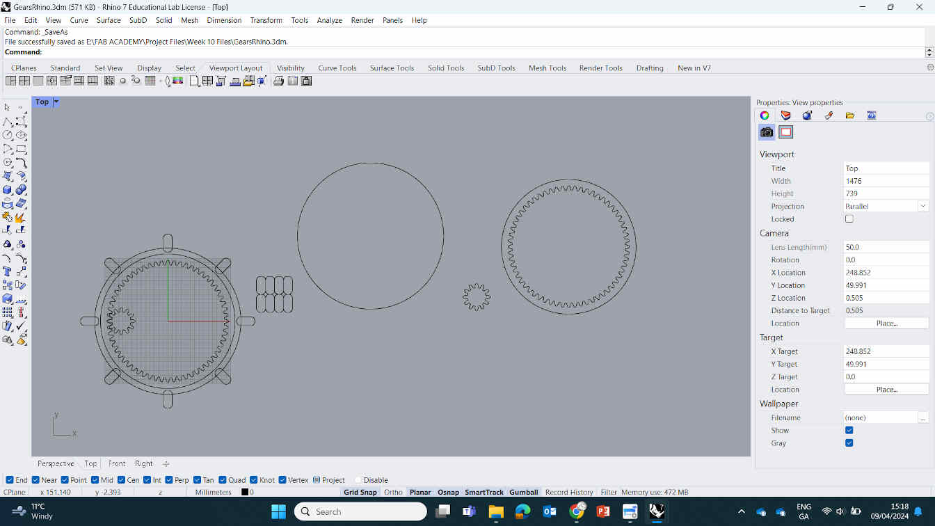
    He drew out what gears we needed and I suggested we use the visual representation given to us at the website Gear Generator, then copy the measurements we are happy with into STLgears.com so that we could download the dxf file from there without the paid restriction that comes with Gear Generator.


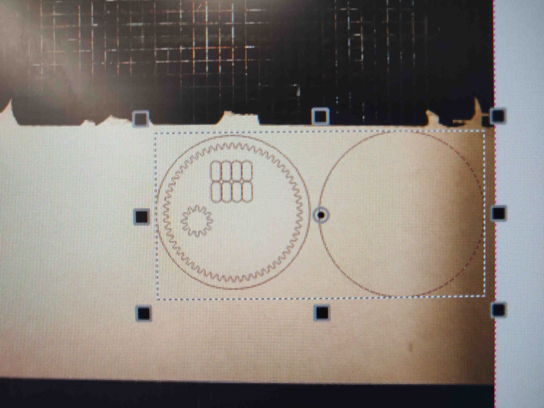
    We manipulated these designs in Rhino CAD software and added a new platform for the base. Then I brought the design files into Coral to be laser cut using the Epilog machine with Cardboard. They were beautifully cut - make sure to check the video to see for yourself.


    After the cardboard was cut, I set up the little man w/ pint glass, that I designed the night before, to be printed on the Ultimaker3, along with a Servo holder I designed in Blender.


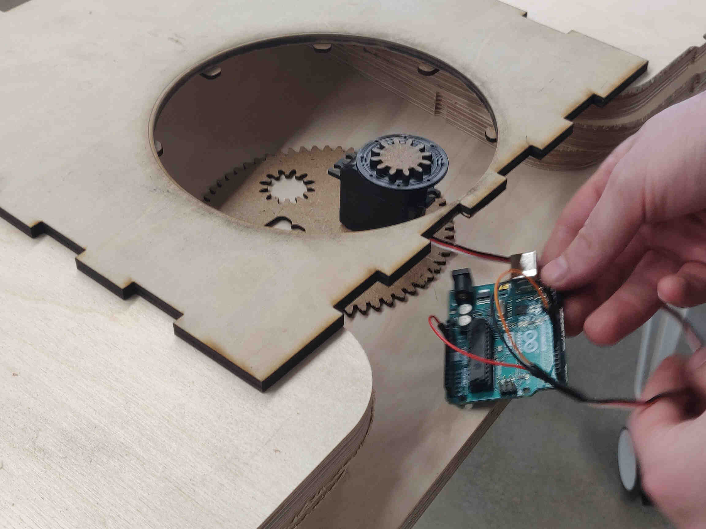
    After some assembly, we positioned the servo motor under the Bartender Pub model and attached the gears. It worked like a charm! The platform is a bit low but I see a lot of potential for mixed media using putty, nature and aerosol! So much aerosol!


    ____________


    Final Video Showcase!


    VIDEO SECTION

    Laser Cutting & Assembly


    ____________


    Conclusion / Reflection

    This week for machine building was fun and interesting as it was entirely as a group project. I was able to confidently focus on the Design & Fabrication process and leave the Electronic & Programming elements to Oscar. Any time there's a design week I always get excited because I have free reign to enhance my skills while producing something fun to build and look at. My work may never be “practical” but it gives me a lot of pride in my work to do something unique.

    This week, after some debate, we settled on a form of Cuckoo clock but with a different form of functionality. It required a lot of work from the full group, learning daunting-yet-useful design tools such as Gear design and multi-level construction & assembly. There's always some form of problem solving in design but I usually feel confident in finding a solution - unlike when I need to problem solve electronics or debugging.

    In hindsight, there were a few ways I could have made the process easier - such as choosing different material thickness for the gears, creating a larger clearance between panels, as well as cutting a large hole in the side or bottom of the machine for easier access to the electronics.

    I feel very satisfied with the end result. I really want to paint our machine and add some scenery but I needed to stop myself from focusing on aesthetics for time management reasons. I'm looking forward to the day I can spend time stylizing it, but I need to focus entirely on getting weekly assignments completed. Also happy I got to edit the 1 minute video of our machine as I love video editing.

    All in all, I'd say it was a very successful week!


    ____________


    Week 10 Project Files

    Week 10 - Project Zip Folder

    Arduino FMCU, Input/Output Code

    Week 10 - Project Zip Folder