Week 6: Embedded Programming
Group Assignment:
- Browse through the datasheet for your microcontroller.
- Compare the performance and development workflows of other architectures.
- Document your findings on the group work page and reflect on your individual learning experiences on your personal page.
Individual Assignment:
- Write a program for a microcontroller development board that interacts with local input and/or output devices and communicates with remote wired or wireless devices.
Sections in page:
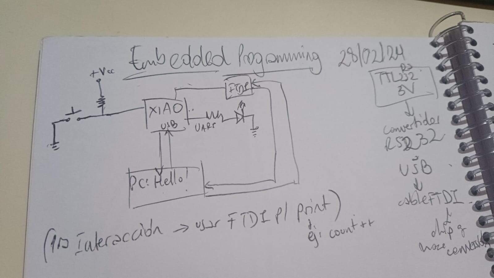
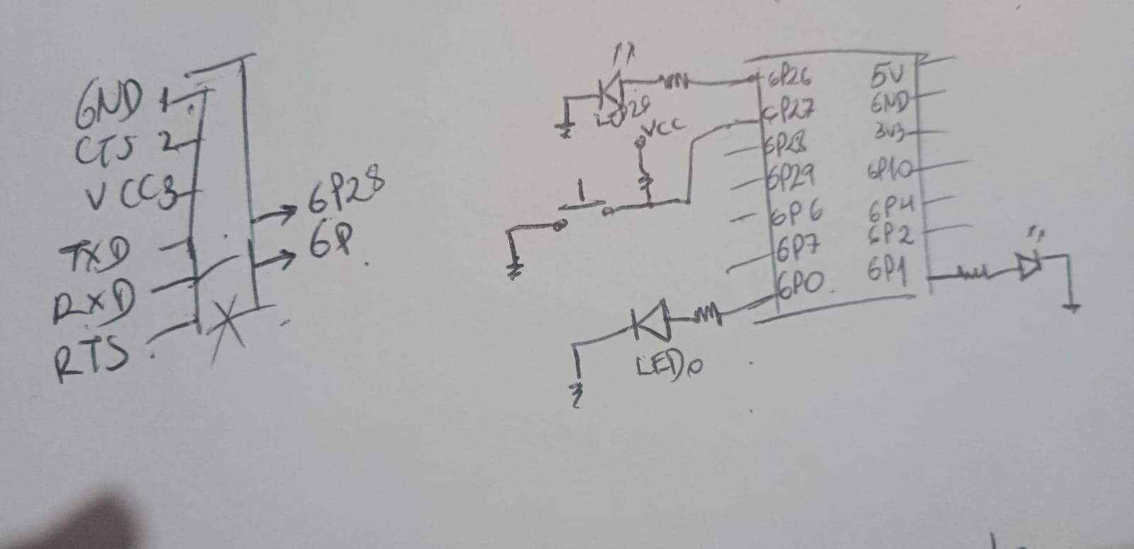
- FTDI Testing
- MicroPython vs Arduino
- Changing between programming environments
- Using an Arduino UNO
- Embedded programming for the final project.
This week was particularly challenging for me. I was unsure about the specifics of the assignment as I had some experience with programming during the fourth week of electronics production.
FTDI testing
MicroPython vs Arduino button-blink
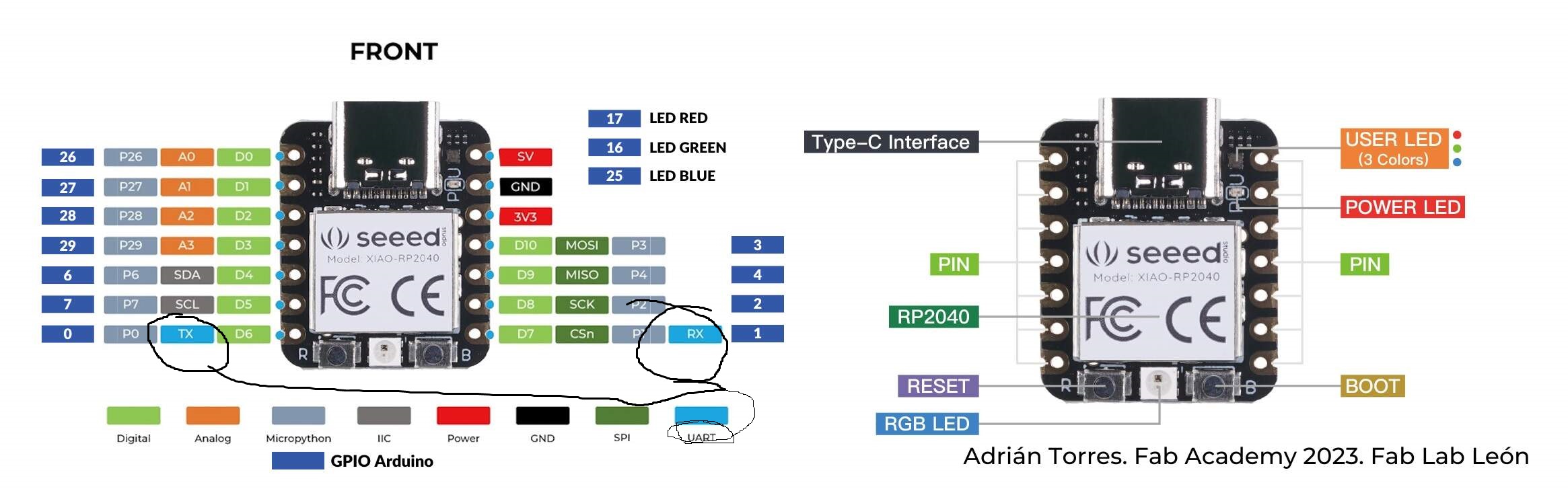
In the next days, I put my mind in experimenting with both architectures for my little Quentorres, using MicroPython and Arduino by testing programs, specifically the one that Neil showed for the RP2040
The first thing that I changed were the pins where the button and the led are connected. Well actually just the button pin, since the led was already in the same port that was specified in the program. I also saw in my first test that the button actually turned the led off instead of turning it on so I changed it to have it backwards only in the part of the “led.value()”
The program that Neil left actually had some libraries that I haven't really used in-depth before and I wanted to know exactly what the code was doing. That’s why I went to chat GPT and asked to have the code commented and explained to me in an easy way.
Here is where I found out that apparently I had problems with the code because in Neil's program, the code had a PULL UP RESISTOR for the button. But turns out that our little Quentorres has a PULL DOWN RESISTOR in its button. And that basically makes the logic be completely wrong in the program.
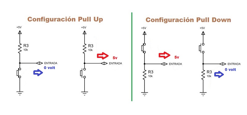
I basically had to change the section of the code where the conditions were. To make the program logic tally with the circuit
        if button.value() == 1 and button_up:  # If button is pressed (input is high and button up is true (before the press))
            led1.value(1)  # Turn on the LED
            print('button down')  # Corrected statement to indicate button press
            button_up = False  # Mark the button as pressed (leaving it as new value
        elif button.value() == 0 and not button_up:  # If button is released (input is low and not (button up) cause logic changed it before.)
            led1.value(0)  # Turn off the LED
            print('button up')  # Corrected statement to indicate button release
            button_up = True  # Reset the button state to released
Changing between programming environments
Since I wanted to test both Python and Cpp with my little board, I had to keep on changing the firmware in the chip.,
For the Arduino to be able to correctly work with the Seed Xiao, I had to go to the page that had all of the RP2040 boards prepared for Arduino and install it in my IDE. I followed their tutorial on how to install this.
Here is all of it very detailed.
Warning:
When actually trying to load your program from Arduino, do not forget to clean the board from the previous firmware, otherwise you're going to get an error and your code won't be able to load.
Now, when it comes to the Micropython environment, I already made tests in the Electronic productions week, and there I explained my process with it.
I did the same thing that with the MicroPython environment. First, just changed the pins with the ones in my board. And tested it, and of course it was not doing what it needed.
Procedure was like before. Taking off the PULLUP part in the button, and changing the logic a bit. And worked like a charm
Comparison between the working codes in both programming environments.
|
Micropython Code |
Arduino Code |
Comparison comment |
|
from machine import Pin import sys, select, time |
none |
In micropython you gotta import some libraries in order to work with your hardware, while in Arduino, its improved API allows you to abstract the sections that are considered a core part of how Arduino works. If you have the board installed, you don’t need to #include libraries that are part of the core of Arduino API. |
|
led1_pin = 1 button_pin = 27 |
#define led_pin 1 #define button_pin 27 |
Creating variables in Micropython is easier than in Arduino, since you don’t need the #define. |
|
led1 = Pin(led1_pin, Pin.OUT) button = Pin(button_pin, Pin.IN) |
void setup() { pinMode(led_pin, OUTPUT); pinMode(button_pin, INPUT); Serial.begin(9600); Serial.setTimeout(10); } |
In MicroPython there is no need to initialize the communication, since we are using the shell of our programmer. In Arduino we do. Pin() and pinMode() act very much alike. You gotta specify the port number, and if it is an input or output pin. In Arduino, all of this is done in the void setup() function. |
|
button_up = True |
bool button_up = true; |
Again, creating a variable in Arduino requires you to specify the type of your variable, while python doesn’t. |
|
while True: |
void loop() { |
To create an infinite loop, python and Arduino work differently. In this simple program, in python we only need a while True, that basically never breaks, in Arduino, you put the code you want repeated forever inside your loop function. |
|
ready = select.select([sys.stdin], [], [], 0)[0] if ready: |
if (Serial.available()) { |
Checking for inputs of the keyboard is done differently, cause one uses the system stdin function, and the other uses the Serial monitor input. In the system one, we save it in a variable that then is used in a conditional. For Arduino it is different, cause you only need to know if there was a communication in the serial to start this section. |
|
line = ready[0].readline().rstrip() if line: led1.value(1) |
digitalWrite(led_pin, HIGH); String s = Serial.readString() |
The order here is backwards. In python, we read the line first and if there is a line we turn the led on, and in Arduino, since the serial is already available we already turn the led on. After that, we read and save the information read in the serial. |
|
print('you typed:', line) time.sleep(0.1) led1.value(0) |
Serial.print("you typed: "); Serial.println(s); delay(100); digitalWrite(led_pin, LOW); |
Micropython only needs one print done to show the complete message. Then uses the time library, with its sleep function that lets it wait for 100 milliseconds. For Arduino, we need to print 2 lines, and wait with the delay() function that is in millis already, so we use 100 instead of 0.1 |
|
if button.value() == 1 and button_up: |
if (digitalRead(button_pin) == HIGH && button_up) |
Both use the if conditional. button.value() checks for the value of button in python, and digitalRead(button_pin) goes for the port where the button is to read it and compare with the HIGH state to see if it is on. The “and” is written as is in python, and like && in Arduino. We check our button_up flag value, if both are true, we go into the conditional. |
|
led1.value(1) print('button down') button_up = False |
{ digitalWrite(led_pin, HIGH); Serial.println("button down"); button_up = false; } |
We set the value to HIGH in Arduino, and we use the 1 to indicate an on value in python. Printing using the shell for py and using the serial in ino, of “button down”. Then changing the flag to False, since our button is being pressed. |
|
elif button.value() == 0 and not button_up: |
else if (digitalRead(button_pin) == LOW && !button_up) |
The “else:” is replaced for an elif in python, which allows to create a new condition. And in Arduino we need to write it as it actually is: else if. The condition now is that the button_up has to be negated. Both languages are different. Python uses the not directly. And not is written as ” ! “ in Arduino. |
|
led1.value(0) print('button down') button_up = True |
{ digitalWrite(led_pin, LOW); Serial.println("button down"); button_up = true; } |
Like before, LOW is how to put a value in off in an Arduino. And 0 is for python. |
One more thing to consider is how Arduino needs the semicolon in each line, and the sections are clearly separated by the keys. In Python, sections are created with indentations, which can be confused.
Using an Arduino Board to do a blink-button
The last thing I wanted to do was to try and test the same procedure with an Arduino UNO board. Just to see if the thing was different. And well, it was
First of all, Arduino UNO is not really supported in MicroPython. We can't really program it in there, so that was out of the game.
Now another thing to consider is that the Arduino UNO didn't have the button, (the XIAO has one because the design we had.)
So I used my Arduino KIT and took an example directly from the Arduino page that worked with a wired button and the prebuilt LED in pin 13
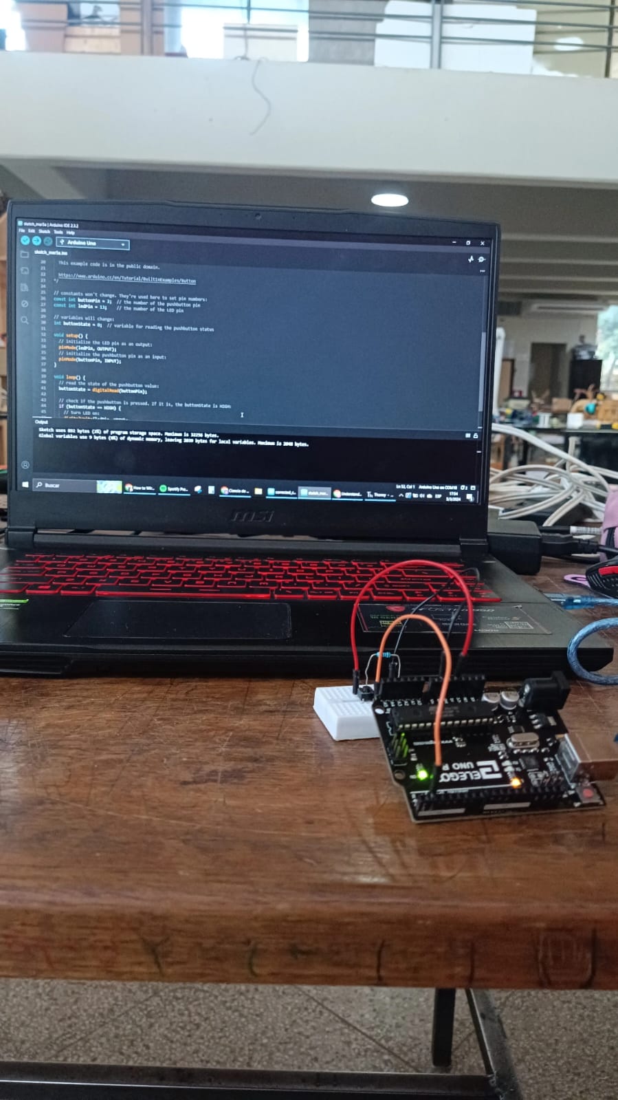
The code is presented here:
              /*
  Button

  Turns on and off a light emitting diode(LED) connected to digital pin 13,
  when pressing a pushbutton attached to pin 2.

  The circuit:
  - LED attached from pin 13 to ground through 220 ohm resistor
  - pushbutton attached to pin 2 from +5V
  - 10K resistor attached to pin 2 from ground

  - Note: on most Arduinos there is already an LED on the board
    attached to pin 13.

  created 2005
  by DojoDave
  modified 30 Aug 2011
  by Tom Igoe

  This example code is in the public domain.

  https://www.arduino.cc/en/Tutorial/BuiltInExamples/Button
*/

// constants won't change. They're used here to set pin numbers:
const int buttonPin = 2;  // the number of the pushbutton pin
const int ledPin = 13;    // the number of the LED pin

// variables will change:
int buttonState = 0;  // variable for reading the pushbutton status

void setup() {
  // initialize the LED pin as an output:
  pinMode(ledPin, OUTPUT);
  // initialize the pushbutton pin as an input:
  pinMode(buttonPin, INPUT);
}

void loop() {
  // read the state of the pushbutton value:
  buttonState = digitalRead(buttonPin);

  // check if the pushbutton is pressed. If it is, the buttonState is HIGH:
  if (buttonState == HIGH) {
    // turn LED on:
    digitalWrite(ledPin, HIGH);
  } else {
    // turn LED off:
    digitalWrite(ledPin, LOW);
  }
}
This was pretty easy to follow and I finished quite quickly.
Embedded Programming for the final project
Motor Driver programming
The first thing I tested with programming was the motors, since I needed to have them moving before actually going into how to control them with the touchscreen. So as explained before, this was a very long process of going through 3 different chips that worked as h-bridges.
I tried to understand how to connect them and control them with ChatGPT helping me, I knew I wanted to use the Arduino IDE to do the whole thing since I have seen that it is way more reliable with the libraries and so. So I started to look into how to upload code with it into Raspberry, and apparently is very much the same as a XIAO, since both are controlled by an RP2040 chips.
Anyway, I went ahead and started a conversation about how to use each of the drivers I was testing with ChatGPT. Here you can read the whole thing.
In the conversation, it is seen that each program is very alike, since the logic is always mostly the same, what usually changes is the way the signals are sent. Sometimes the PWM is already built into the pins that control the direction, sometimes it needs the Enable pin to send that information in a different channel.
Its way more convenient to have the PWM already integrated to the direction pins too, since it reduces your need for one extra connection, but the Enable pin also helps you control the movement with more precision. So really depending on the application, you need to choose which is better. In my case, the important thing was to control the speed when the robot needed to turn, because I wasn't using any sensors to see the angle of the turn be exact. That is why in the final iteration you will see my program using only one motor moving to turn.
The basic idea is that you need to create functions for each type of movement where the pins are set to HIGH or LOW and if needed, with an analog value for PWM that will help control the speed of each motor. Also it is important to make both motors work simultaneously, so turning them both on, or both off is also to take into account into each function created.
At the end, the motor control section will be loaded into the main program, and as it was said before, the only time it actually worked well was with the L293D bridge. Here a little video of it working:
Touchscreen Programming
For this section, I went ahead and took inspiration from an example that I saw used the ILI screen too on youtube, I did some research to find out how to use this touchscreen cause I wanted a very interactive UI that could be used completely on the screen, this will allow me to make as many changes to the whole thing as I needed to make the project be expandable and grow with new modules if I wanted to make that happen, but as you will read, things didn't go as planned and many things had to be changed throughout the process.
At the end of the day, the programming was not exactly the problem, it probably was a hardware thing, which I unfortunately was not able to check because I only had one screen (which I tried to really protect cause it was the main part of the project lol). But here, a summarized explanation of what happened with my programming of this final project.
Inspiration and Analysis.
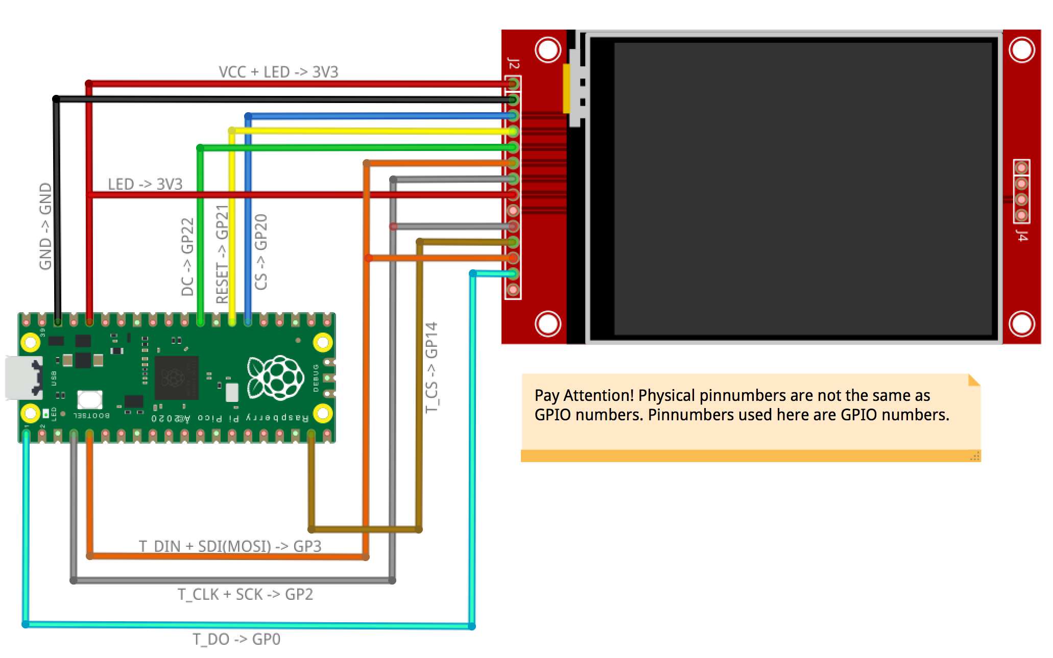
So like I said before, I found a tutorial on how to create a touchscreen matrix with the ILI9341 on youtube that I used as a base to create my project, actually, that is where I took the pinout from. So of course, I knew that the code was gonna go in that route as well for what the project needed to be. This is the link to the project on instructables.
I started by asking ChatGPT to explain to me the whole code to understand each section and what it did better. Which will later help me update it with what I needed for my application. The whole conversation used for this section is in this link you can follow along with the explanation given here of the thought process.
Basically, the code allows me to create a matrix with buttons and each button can be programmed to do something if I want to. The whole thing works with TFT_eSPI as a libraary for the connection between the Pico and the Screen, using the SPI bus as the main way to send the commands. The buttons are prepared with the Keyboard library and the calibration is done by using the FS library and LittleFS one. This allows the program to create a space inside the memory of the Pico to save the information needed as calibration and use it for the application.
Everything else is the logic to make the program work, you basically setup everything and create the display matrix, and then you create the functions that will control the buttons by reading what the touchscreen is sensing, which is all read as coordinates in x and y, and those values are enclosed inside a section of the screen that is where the button is. If you touch that section where the button is placed and the touchscreen senses it, it saves it in a variable that is used to activate what that specific button is supposed to do. You can completely customize this and create even newer matrix based on those buttons. That is the basis of the code.
Another important part of the code was the calibration section, which basically is a function that comes inside the TFT_eSPI library already, that helps you have more accurate readings with the touchscreen. You have a little arrow in each of the corners that helps you have the values of the touch reading saved to use as the limits of the screen.
Something else very important in this code and in using the TFT_eSPI library is the "Setup.h" file, in here is where you put the values of the ports and connections needed for the program to work, which basically connects the library to the parts that you need for each chip to work. In my case, the Setup file needed to have the ILI9341 driver, and have all the needed connections in specific ports that were connected to the Raspberry Pico as it was shown in the pinout from the tutorial.
All that info was loaded into the setup file and used for the program too.
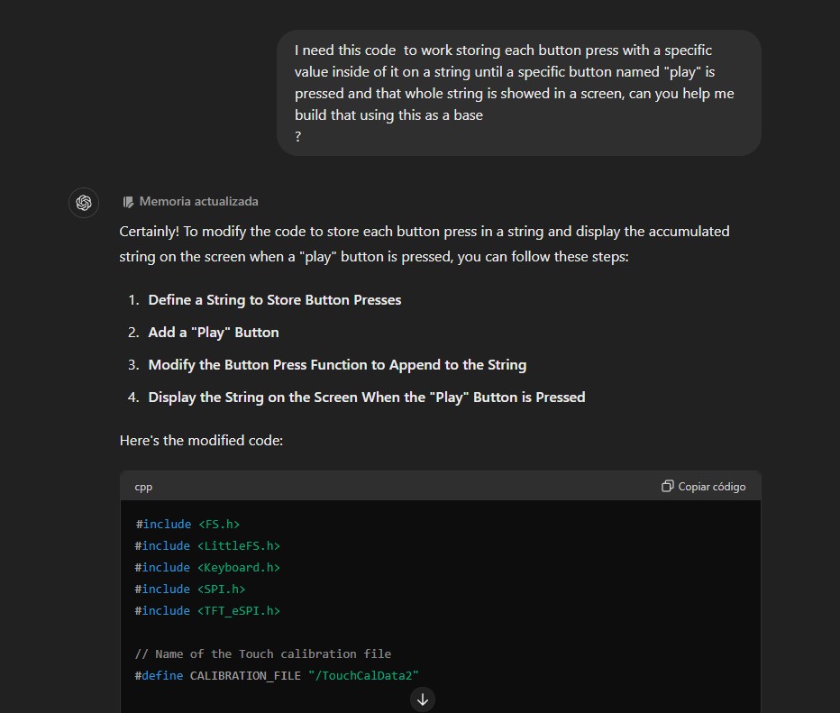
I started working on the program in ChatGPT, by basically asking the changes that I needed to implement for my application. One of them being that I wanted a concatenation of each button press stored in a variable, which would then activate things after the "play" button was pressed, basically making the stored values be revised again and each value activating something specific.
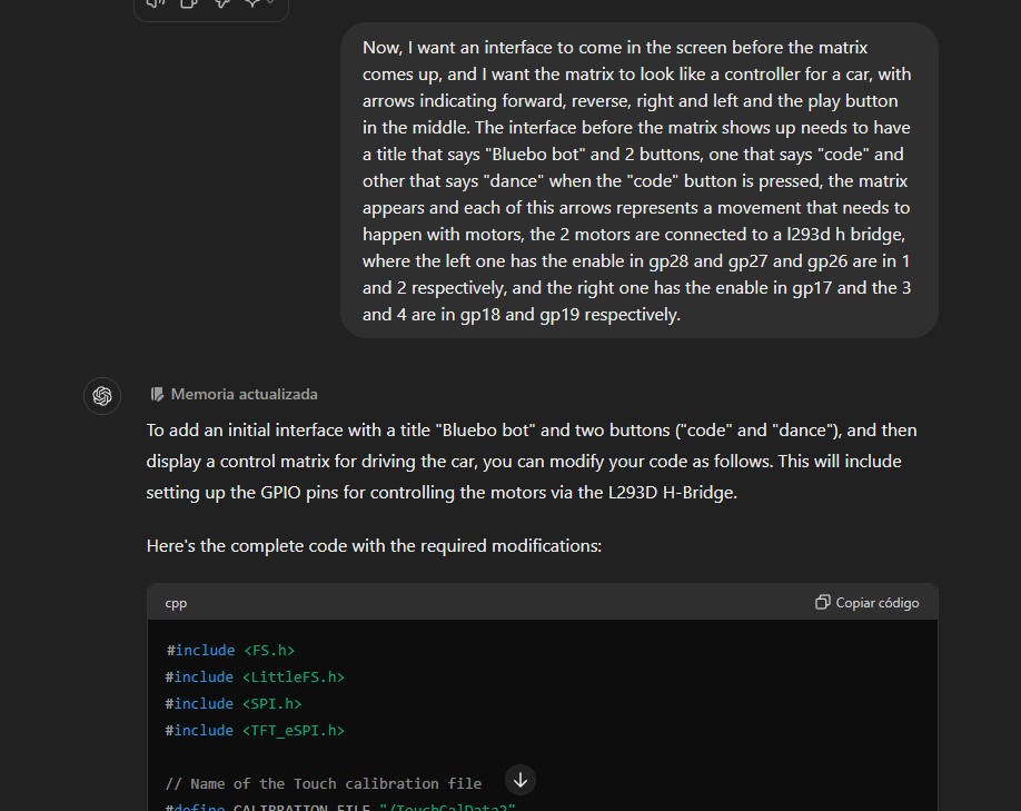
I also started already thinking of the UI matrix like the arrows section of a controller looks like, the starting screen with 2 modes too and asked to have that implemented. This part with the motors taken into account already, since at this point I already had the L293D pcb working for me. All of those changes where starting to become part of the program inside the ChatGPT conversation and I was looking and trying to understand all of the code that it was giving me to see if I needed to make changes. I was doing all of this while the pcb was being machined so I could test it after soldering. And to save time I was taking every bit and putting it into a draft in Arduino IDE to test it when I had the chance.
There were some things added to the program before being actually able to test it, until the time the pcb was ready and I could start with the demo of the whole code.
My first iteration for the program didn't work at all. The screen didn't even turn on, nothing was showing up, even tho apparently everything was right. I was pretty confused.
My mistake was to try and implement everything at once, because troubleshooting the code became a real nightmare to be honest.
Troubleshooting
So here is the deal, the part about making the touchscreen working, was actually pretty tiring. To make it short, I tried a lot of stuff. At the beggining, I realized that the first problem that I had was that the tutorial that I had was for a ILI9388 not the ILI9341, so the Setup.h was wrong because the driver was not for the chip I was using. But before actually realizing that, I even went to test the whole thing in MicroPython, but honestly working with external libraries in there is a little bit annoying, and even ChatGPT was getting confused with how to use the libraries. I understood that the chip for the touch section is a different one and that needs another library, but the one suggested by ChatGPT was deprecated and the other ones I found were with CircuitPython, so that made things pretty confusing. I only wanted to see something appear in the screen but nothing was working I started to fear that I broke my screen. Luckily it wasn't the case.
Like I said, in the Arduino version, the main problem was that I actually was using the wrong driver for the TFT_eSPI library cause I was not paying enough attention lol. When I changed the driver in the setup file at least something was starting to show up in the screen yay.
Now, the problem was the touchscreen, after the calibration section, which did work and allowed me to actually have something sensed with the screen, no button was working. And nothing appeared in the screen either.
I began to test the touch only, with a little program that I found in the Tft library folder as an example to see how the "getTouch" function worked and all.

In there I could actually see some values when I was testing it, like, the touch was "working" but the thing is that the coordinates that showed up where kind of not making any sense. The values were too big for the size of the screen, and I couldn't really understand the whole thing. I tried testing with other functions as well, and trying even with a different library, but to be honest, the thing wasn't working for me.
The main problem was that the values where out of the context of the scope, and another thing that started to happen later was that the calibration was being done "automatically", meaning, that it detected touching even when none was happening.
At this point, and after making many different approaches as it can be seen in the conversation with ChatGPT, I decided to change my sensing method, as it was apparent that most likely, the touchscreen part of the component was broken or malfunctioning.
At that point, it was the moment I went into the Button Matrix method. Were I used 4 physical buttons instead of the buttons appearing on screen to control the whole program.
A lot of the logic remained mostly the same, but at the end the "keyboard" library was not really used, there were just instructions in the screen not buttons that needed to be touched.
When the program began to actually work, it was when the details went into account.
For example, to have a more easier to understand look, there were "buttons" created by some rectangles that were defined beforehand to show the modes that were available.
Also, the logic for the use of the motors was slightly changed, as the way to read each state was not a char anymore, but a whole string with each movement so you could read the movement when the program was started. Colors were also shown in the screen when each button was pressed, representing the one that was pressed in that moment. And each had colors also implemented in them.
The "dance" mode was also created, which consisted in making the robot move in different random directions for 10 times and show variable colors as well, and at the end of the whole thing there was an "applause" section shown.
Little changes where made before the final version, mostly to have a nicer UI and having buttons that looked nice. Having the things be as centered as possible, having different sizes of letters where needed and also the timing for the movements after testing it. At the end, we got many functions that controlls the whole program effectively, with debounce of the buttons and a very responsive handling of them that allows the program to be pretty smooth.