System integration
-
Design and document the system integration for your final project
Fabrication Process
Bluebo is going to have many different parts. In this iteration of the process, I have made the decision to focus on encasing it nicely, so everything looks integrated in a cool package.
I plan on designing the main body of the robot, which will be a little encasing for the whole parts that has 2 main wheels and a 3rd one to help keep balance in the front. All of it is being designed using Fusion with some models inside that are part of the system being grabbed from GrabCAD library and Thingiverse where needed, to save time.
Making the body of Bluebo
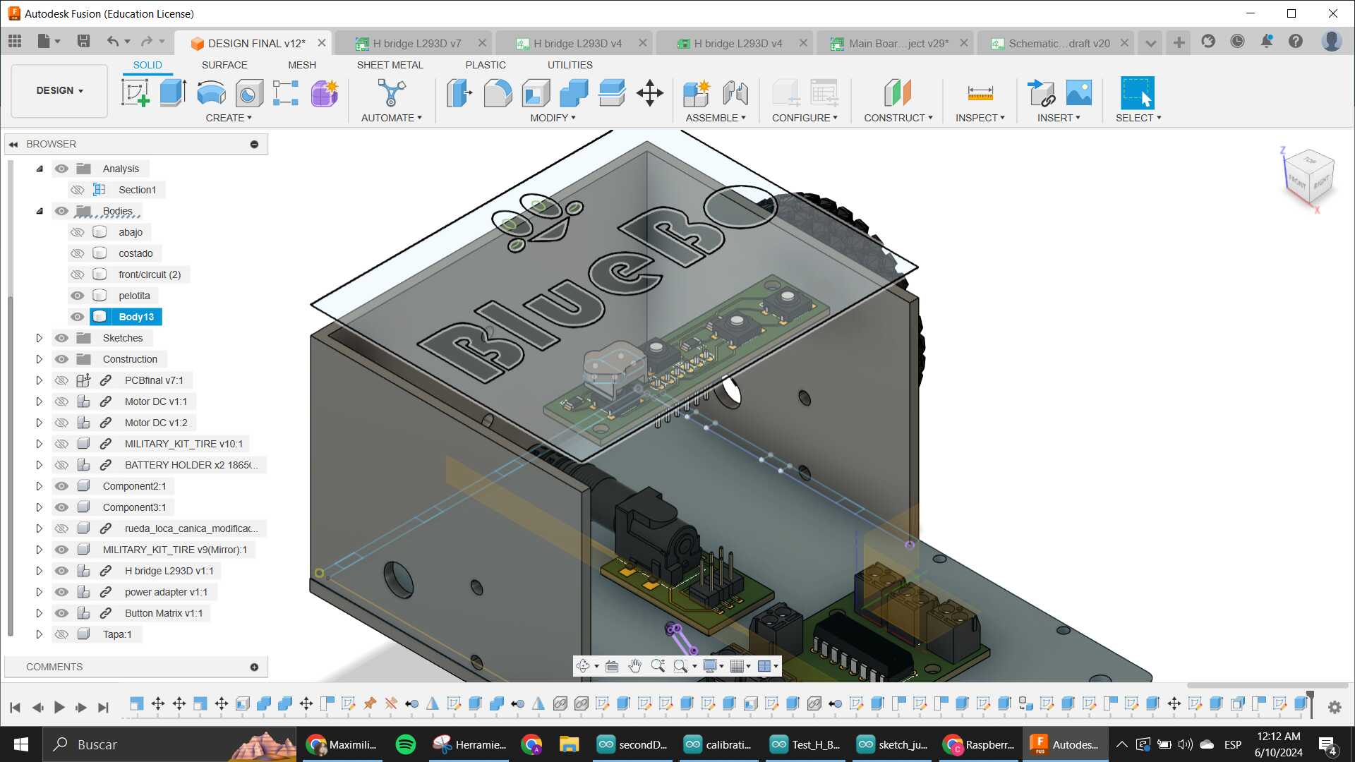
I made the body thinking about how the usage would be, that is why the front has the inclination where the screen goes, this is also the first thing I planned cause I knew I wanted the main electronic board to go behind the screen and have the Pico on the opposing side. I actually designed the whole packaging surrounding the main board which was the first electronics done in the project that is why in the video you can see the design being started with that PCB inside already. It was crucial to me to have that there to measure everything.
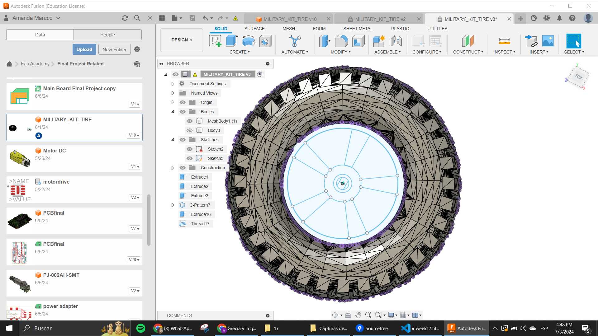
The sides also needed to have the motors taken into account so that is when I went to GrabCAD and looked for a reference of the gearbox motor I already have and downloaded it. Here is the model that I used. When I had that, I used the wheel I had already molded which came with an STL file. This required me to make some changes on the size to the design, cause at the beggining the wheel was too big for the robot.

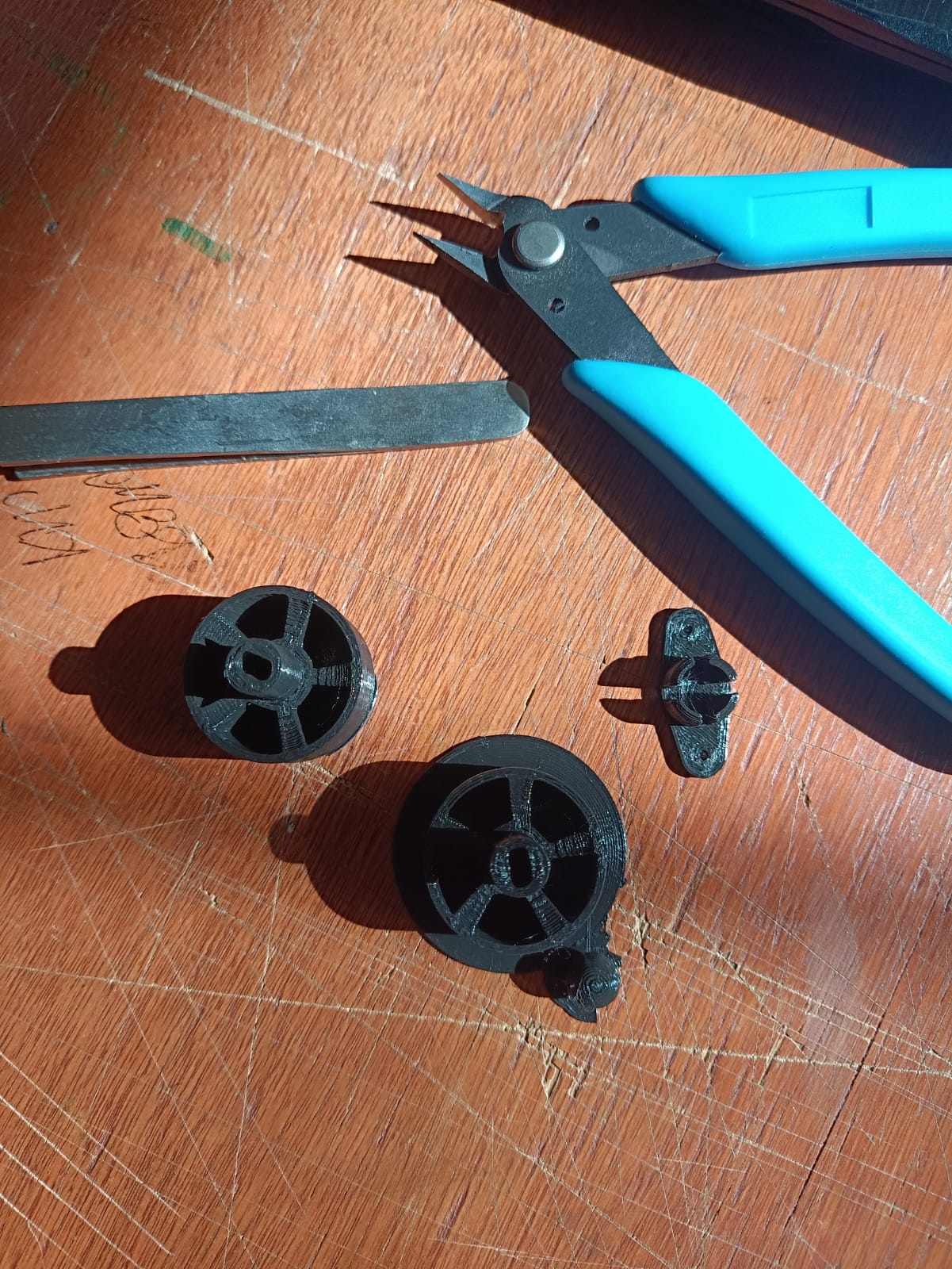
As you can see in the picture, I also made some rims for the wheels so they could fit into the axle that the motor gearbox already had.
Using that and the wheel as a reference, I created a quick design for rims that could be 3D printed and tested.
When that was done, I made some press fit cuts to all the parts (side, front and bottom), to have them be easily removable. I also made holes for the screws to secure the gearbox and also the battery holder on the back.
When the testing of electronics was done and I already knew how the top part would be, I started to design the case for the system.
This part was where the on/off switch was going to go, and also where the Button Matrix was going to be. I designed the thing using the pcb of the buttons to know where exactly the holes needed to be. Those holes will later be where the buttons would go. When I finished designing that, I also tried to include a logo for the robot
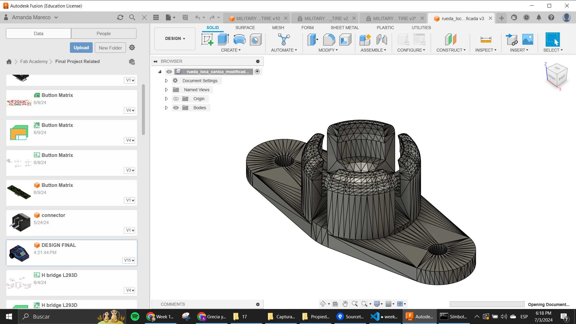
I also included an idler wheel on the front, which was found in Thingiverse, it was made by "alca3d, and I went same process as to with the wheel, changed the size a bit so it could fit in the bottom of the robot without having many issues. This also required me to create a small ball for it, that would act as the wheel.
The buttons where the last thing designed, using the forms of arrows, and a circle with a P to represent the "play" feature.

Fabricating parts
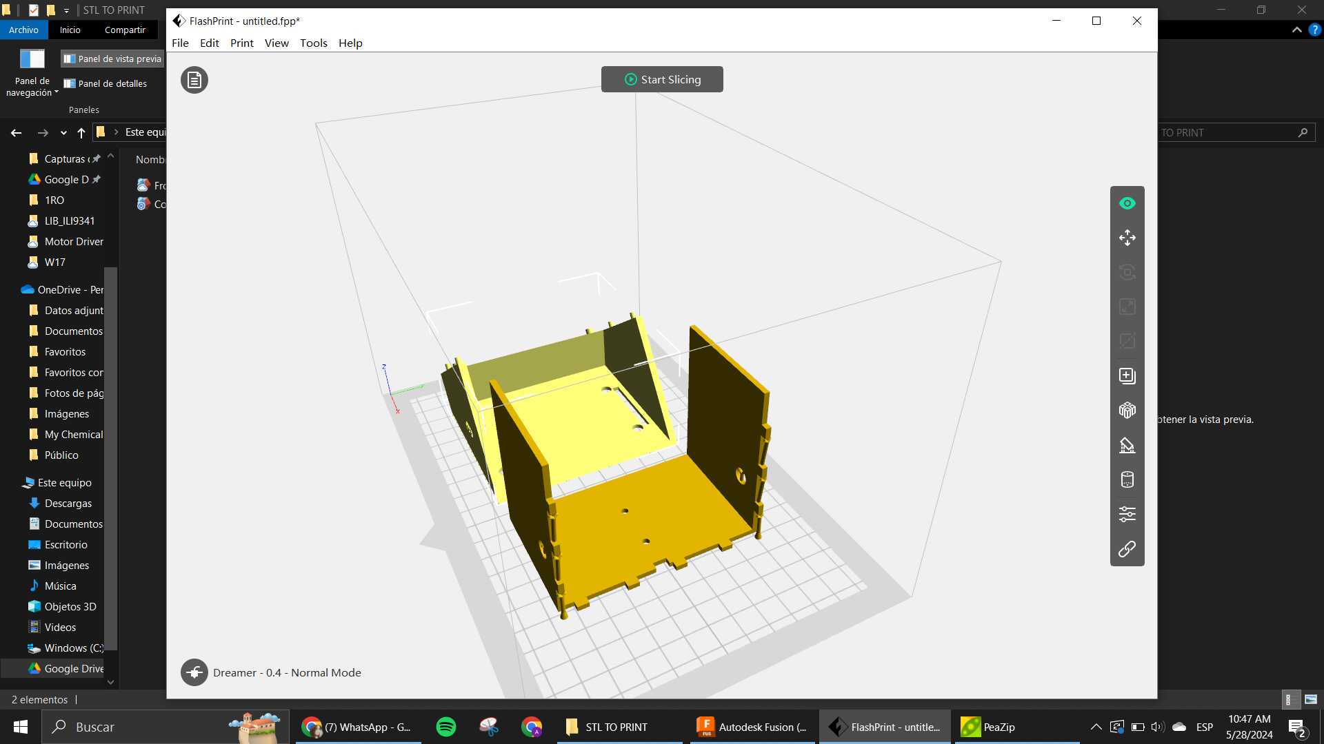
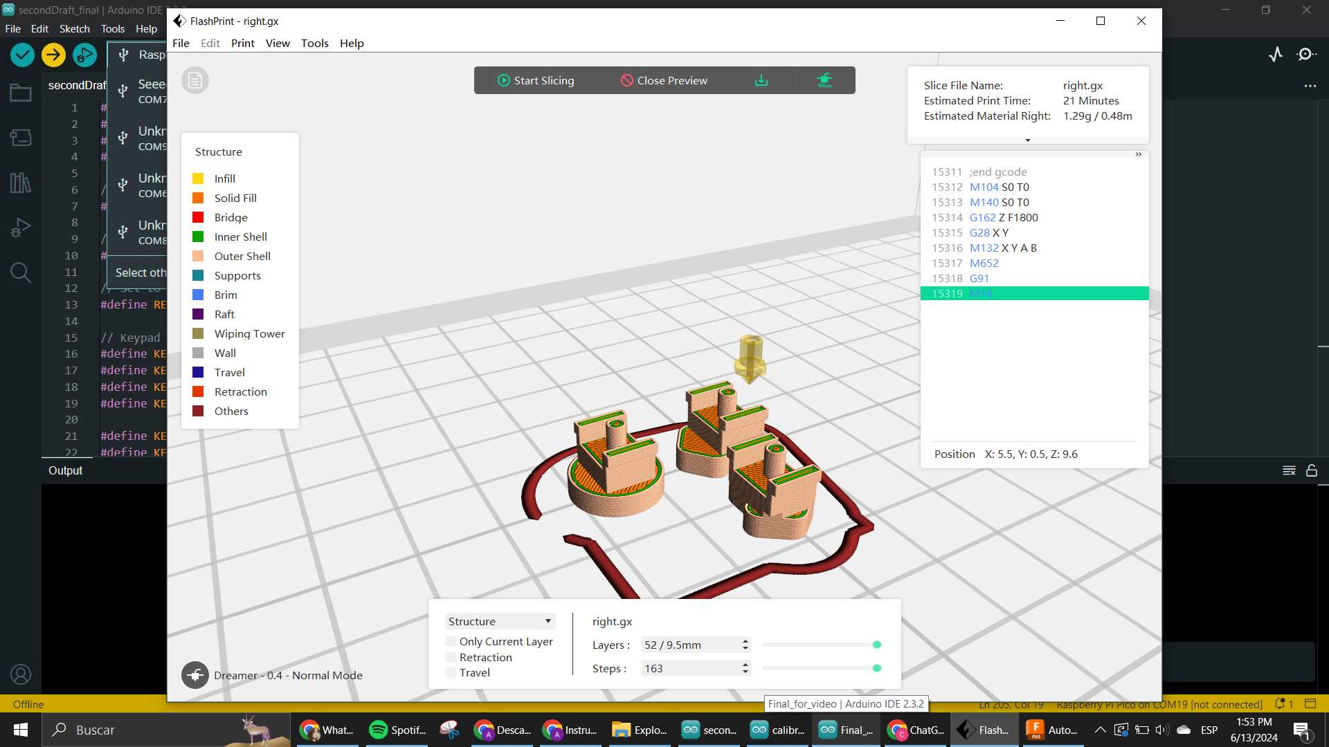
I used the 3D printer to create the front and the sides/back. This was using the FlashForge
I also 3D printed the rims and the idler wheel. This was made 2 times cause the first time the rim was a little loose, so I went and changed it a bit in size for it to be tighter to the silicone wheel.
I used the Laser Cutter to make the bottom of the whole thing. This also suffered some changes when parts where added (the idler wheel and the pcbs for the motors, which where screwed into the bottom)
The other thing I fabricated, but this was already all explained in the Molding and casting week was the wheels, I used the molds again but now to make the wheels kinda green. I also used some clamps to help the process.
You can see the finish wheels with rims in the 2nd pic here.


The last thing I printed, but with TPU filament instead of PLA, was the buttons that would go on the top. This was my first time using this filament, so it was interesting to know what parameters change.
Mostly, the important part is the speed, and the temperature.
Electronics Systems
This was the part where I spent the most time since I really wanted to create everything myself. The idea was to make everything that was planned in the Midterm Review, but at the end, we had to compromise some stuff because there were many things that went wrong in many places while designing and testing all of the electronics that were made. So here, a recap of everything that stayed in the project.
Main Board
Of course we need to have a heart for the whole project, and this was the thing that made the whole process as it was. The board has the Pico microcontroller as the embedded device that controls everything connected. We have the ILI9341 Screen as an intended input and an actual output to show what is going on with the robot. There are connectors on the sides for 2 motors, where at the beggining the plan was to send 2 signals and the VCC and GND as references. But that changed as it will be explained later because of the IC that works as the H-Bridge for the motors changed. It also contains 2 connections for I2C and Serial comm, which will later be used as GPIOs for the Button Matrix.
Designing the schematic
I made so many changes to this board, because a lot of stuff I used where things that I hadn't really used before. For example, the Pico itself, I hadn't really made any board with it, I used the Xiao before it, so I had to grab the library for it and see how to use it.
Here is where everything that was learnt in the Electronics Design Week, was put to test. Things like how to import the library, how to customize your own footprints and so. I had to make custom components for many things in this project. I will leave a folder with everything I used in the EDA on the links on the side.
Firsts Versions
In the first versions of the board I only was thinking about the Screen, and I knew I needed the connectors for the motors but I wasn't yet sure how the board for the motors was gonna be built. Here I started testing with creating my own footprints again, as I knew I didn't want the pico to be stuck to the board, neither the screen, soo I was gonna take the same route that was done with the xiao of using the SMD male header or something similiar.
Sooner rather than later I discovered that this was gonna fail because I actually had to use FEMALE headers for the design to work like I needed it to.
So I had to check which ones where available in the lab, and well, only the through-hole ones where here. At the end this ended up working in my favour cause it made me think that I could try and use a 2 sided pcb and have the pico on one side and the ILI on the other.
When I finished making the connections as I had seen in this tutorial that I wanted to follow, I proceeded to check the motors side of things and see what was going to be my approach as to how to control them easily.
I will later explain with more detail how this went but basically to make the system integration (meaning the cable management) easier, for external boards I was recommended to use this Terminal Block that was super available. As you can see, it is also a through-hole component, so this had to be taken into account when designing.
In the end, I put the terminal blocks on the same side as the pico, because that was gonna be the side inside of the packaging, and while I was doing this things I kept on checking on the 3D model, cause I was already thinking on how it was going to be in the final product.
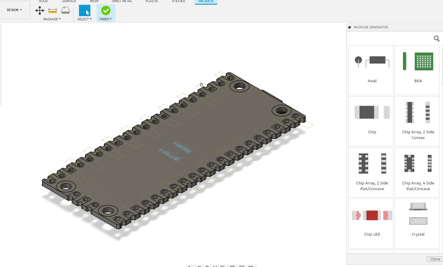
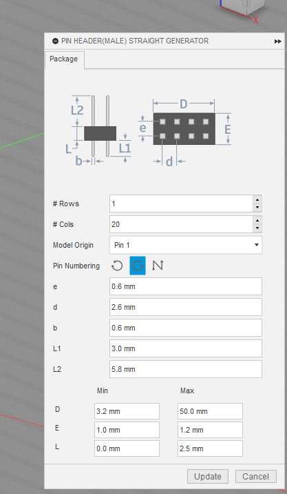
When I placed the Pico, I knew I had to add the male headers that would go soldered to my pico to make it removable, so I tested this "Package Generator" that the library editor has, to make the PICOT.
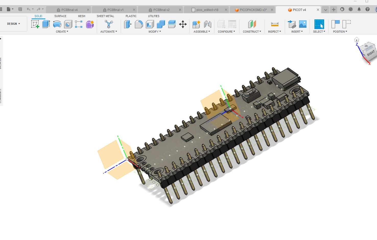
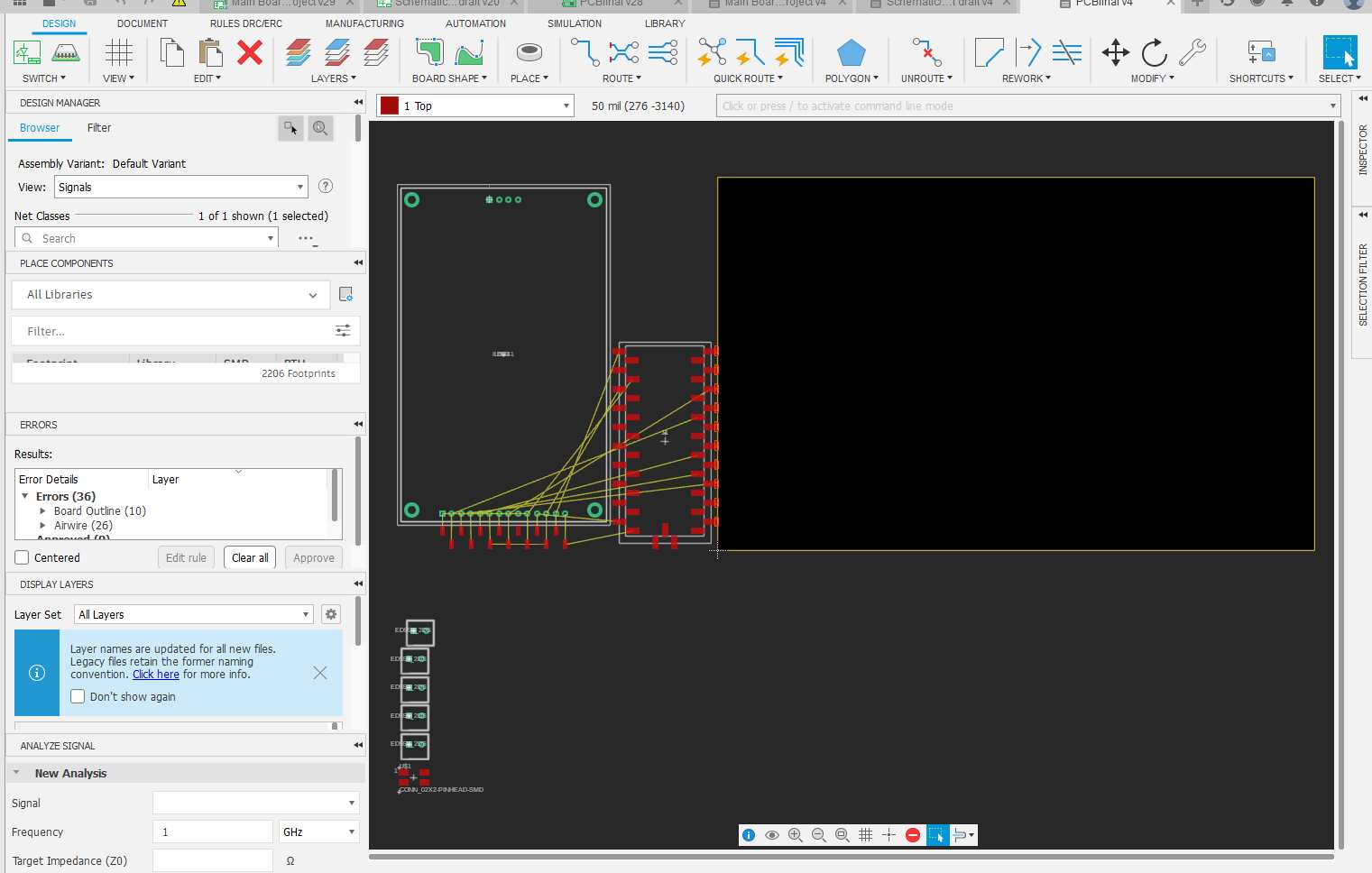
After having the pico 3D ready, I used the component that I found of the ILI9341 as a reference as to how big I wanted my board to be, since that was pretty big already and I didn't want the robot to be way too big. The component was found here but when I started making the PCB and then measuring the actual component I found discrepancies between the size of the outline and the screws it has. I freaked out with that if I'm honest. Was pretty pissed but tried to fix the thing.

I had to look for an exact 3D and go from there, cause if the 3D was not right, a lot in my design was going to be wrong too. The frustrating part is that I actually already had done a lot of the routing and pcb at this point, and having to change this meant changing a lot of stuff. But before going into that, I had a lot of fun playing with the double sided feature, which I hadn't really used before. Using the vias and different layers was actually very interesting.
I went back to GrabCAD to see if I could find an actual model to use for the ILI that was CORRECT. This was where i found this model that saved me.
The nice thing about this model is that it came with dimensions for the stuff, so I could use this to make my footprint too. Now honestly working with the designing tool for electronic footprints in Fusion is actually extremely annoying, I don't recommend it because you have to use the grid for measuring, and you don't really have a ruler, and the dimensions tool is sort of wonky in this part of Fusion. Hopefully it gets better or next time with more time I find good tutorials to follow. But yeah, this process took a little while, cause adapting the holes where the screws have to go was crucial for my PCB to work as I needed it in the final product.
When I finally fixed everything and did a little DRC to the whole thing to make some of the pads bigger and the holes too, I ended up with this:

Production
Taking all of the gerbers out I started to work in the FlatCAM project to create the 2 sided board. I followed this tutorial over here:
I tried to follow as best as possible, using the 2 sided tool to mirror one of the sides that was gonna be the bottom, you have to do it with the bottom and the drilling holes.

You also need to create some alignment holes and mill them to put some screws that will alow you to flip the board in a direction that you choose, I used the same as in the video, fliping it on the x axis.
This holes are to be used after the top layer is finished being isolated, and when you flip the board you put the screws in those holes made when you did the flip correctly in the axis that was set.
I also changed colors and "disabled" the jobs that I wasn't using so it wouldn't get messy in the screen and all.
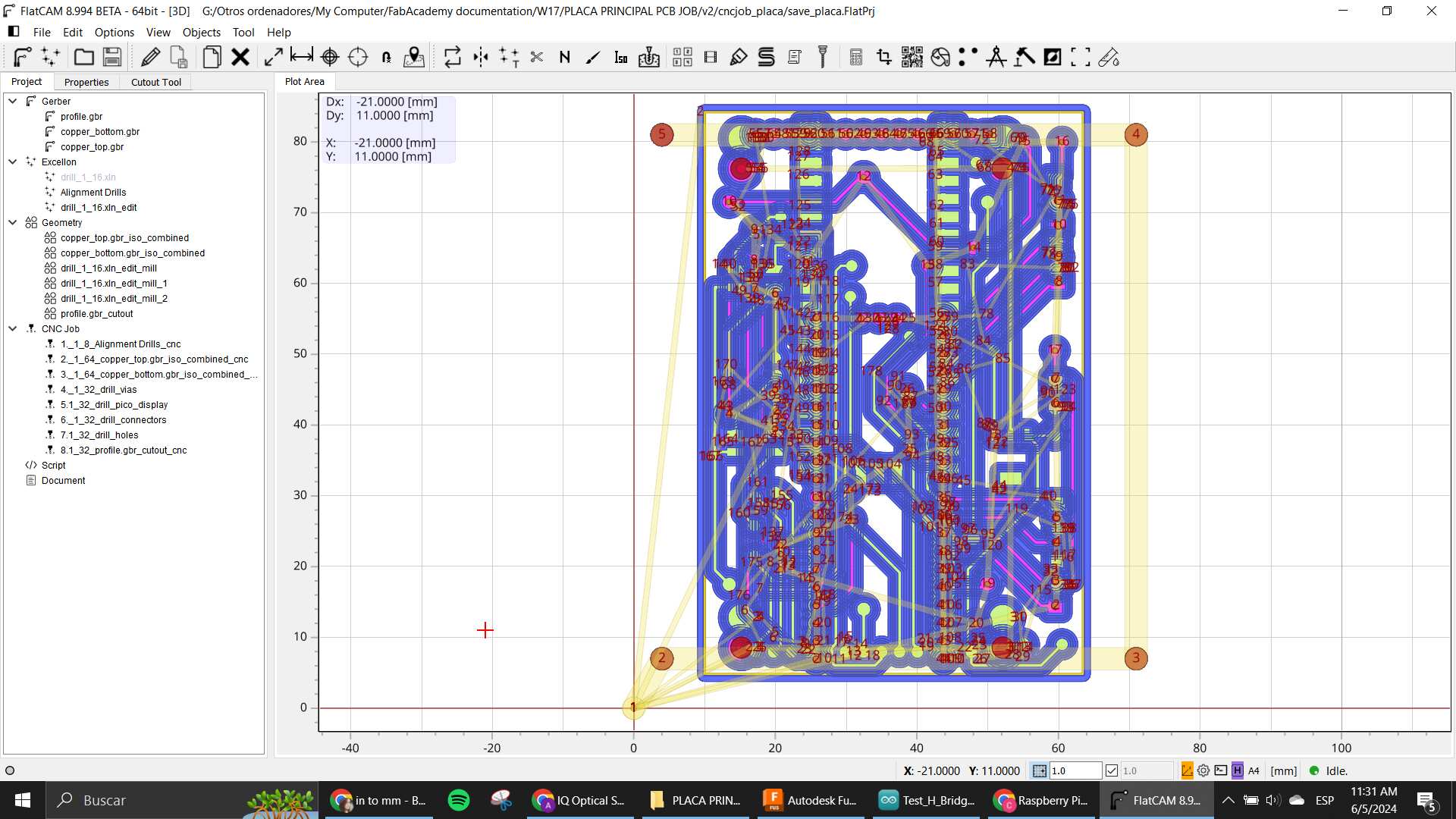
As you can see in this image, where the project is laid out in the "CNC jobs" section, you can see that I numbered the jobs in the order they need to be done. There were so many because the holes were different sizes, and for each size I had to mill with the same tool, but not same diameter of hole.
This process was LONG, VERY VERY LONG OMG. So beware if you want to make something like this, it is going to take at least an hour to prepare the files only.
When all the files were ready I went ahead and started the very tedious process of machining a 2 sided PCB
First, the alignment holes where made with a 1/8" mill cause I had the broken mills to use as "Screws" to align the pcb.
Then, the isolation of the top layer. with the regular old 1/64" mill.
After that, I had to take off the board, and flip it. But thing is, the thing was placed with double sided tape. So taking that tape off was SUPER ANNOYING AND TIME CONSUMING OMG.
Here is where I finally used the mills I talked about to align the flipped board.
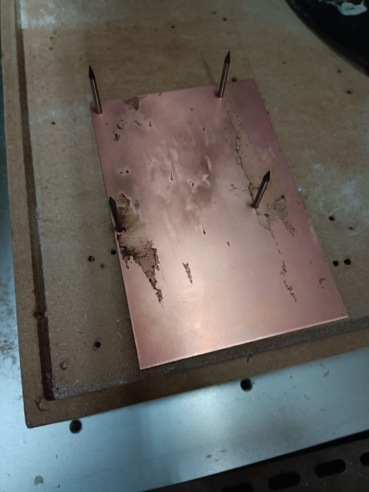
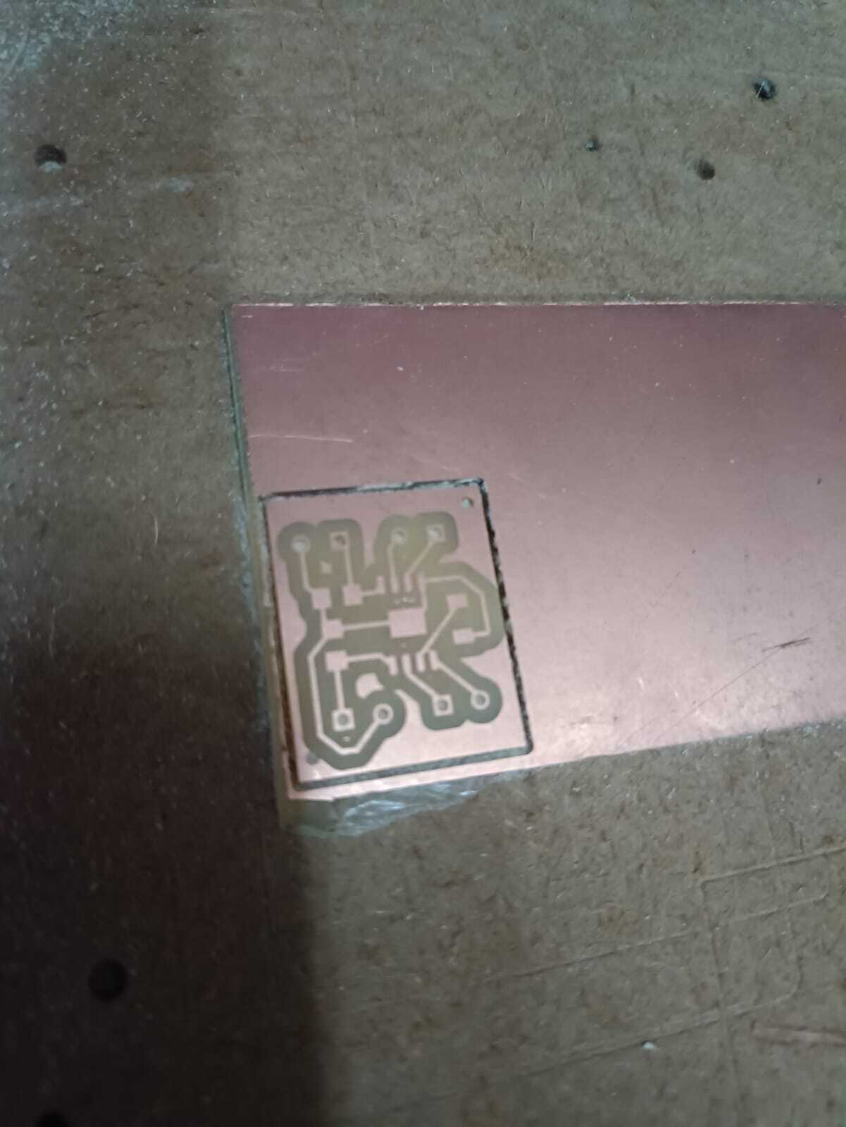
As you can see, the pcb was a little dirty but we went with it (or I was gonna lose my mind). So here you isolate the bottom layer. And then change to the 1/32" mill to start drilling all the holes.
When I did this, it was pretty late at night and I had been working the whole day, and it was pretty annoying when the CNC started to make this:
In the moment I didn't understand what it was, and I was alone in the lab at that time in the night already. But later I found out that I had put the mill inside the collet way too much, so basically the machine already reached its limit and went back to its zero. Thanks to this the process took even longer than it needed to be, and made the holes not be completely drilled in some places.
I tried fixing that the next day with my own hands. I mean, thankfully it kinda worked for me. I used a dremel for this part to fix the holes.

With that done, I started to solder everything together. Another tedious, long process.
The first version of the board was succesful? You can say, but after having issues with the motor driver, and the voltage regulator, I had to change it again. That process was a little quicker, but still pretty tedious, following most of the same steps alreay seen here. One thing to note tho, is that when I made the 2 sided PCB, I had issues 3 times with it not aligning properly. I am not exactly sure what happened on those 3 times, but then I just tried aligning it while soldering since it wasn't that big of a deal in the last try.
Here is the final version of the board
Motor Driver
For this one it was a very arduos process because I hadn't really done anything with DC motors up until this point, and I knew I wanted to have a lot of control in the movement. I was aware of the existence of the H-Bridge, since we saw that in the Output Devices week with Neil.
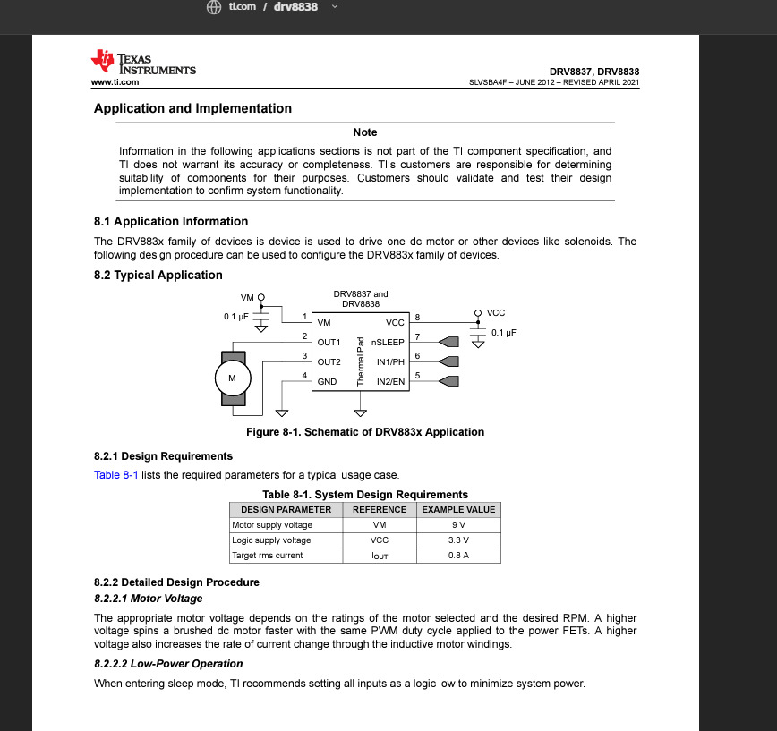
I looked into the inventory that we have from stuff available in the lab, and the only one that was called a "Bridge" in the list was this one.
I downloaded the datasheet and started to look into it, I basically wanted to know how to connect it and the logic it needed so I could separate some pins in the main board for it as it was needed. So this little page was very useful for all of that info.
I downloaded the EDA library to use it in Fusion and started to design the schematic like usual but then I became skeptical when I went to check the pcb component cause when I started the design and put the footprint in it seemed super little (and at this point I hadn't seen the actual component live, so I didn't know). But then, I went ahead and actually looked for the thingy I was super worried XDD

What worried me the most was actually that the space between each connection was too small for the 1/64" mill that we know was one of the smallest ones we had available, thankfully there was one that is 0.2mm because as it is seen here, the isolation with the 1/64 was not enough to go through.
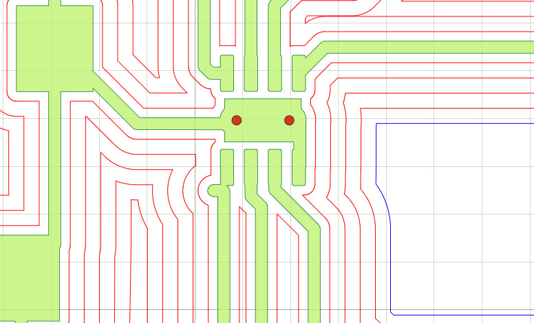
After preparing all the flatcamproject with the settings, (I made the isolation with the 0.2mm only with 1 pass because more than that was gonna make it be the same, it barely made it) here is the project looking nice with the 3 different mills: 1 pass with the 0.2mm, 5 passes w 1/64 and the holes and cut with 1/32
The soldering process for this super small component was also something to take into account. I wasn't sure if I was gonna be able to achieve it, I'm not great with my pulse and also the regular soldering iron is not the usual thing to use for this kinds of components. I had to investigate a bit about that too.
After soldering the super small component with the hot air welder and going on top with the regular iron, I put some cables into the terminal blocks between this one and my main board with the programming and all, but sadly it didn't really work. I tested many things, at one point I even had problems with the voltage regulator that became too hot and started to smoke. It was a big scare. But oh well. After that I just decided to scrap this one and freak out cause I didn't see any other ones in the inventory.
Second attempt
Well, then I found another motor driver in the inventory, I wasn't sure if it was an H-bridge at the beggining, but then looking into the datasheet it was!
The part name is the Allegro A4953 which is also a driver and a h-bridge if you need it to. Connections were almost the same as the other one, but this footprint was exactly the same as an Attiny, which is a bit bigger and easier to solder. I went ahead and changed the same pcb I had with the first one, but now used this IC instead. Added some capacitors and a resistor like the datasheet asked for, and did the whole process again: machining, soldering and testing.
In the testing process I only could make one side work, and not always, I am not really sure what went wrong with this one, because in the first one I noticed after a little that the problem was that 2 pins that weren't supposed to be connected were making a short, which is probably why it wasn't doing what it needed to do. In this one I never truly found the actual issue, my biggest guess is that it needed different kind of capacitors.
Anyway, I was running out of ideas, because I didn't want to use the mosfet method cause it used too many extra connections that I had to include in my main board, and I didn't really want to change that one, cause re-routing so much was gonna take too much extra time. I needed a driver that used the same amount of outputs as I already had prepared.
Lucky for me, I remember that my Arduino Starter Kit came with a motor driver for DCs as well, and thats where I found the L293D.
This component is the old version of newer H-Bridges that are more complete and all, but is very effective with its technology. Only thing that was a little bit of a problem was that it needs 5V of power to function, but nothing a regulator can't handle.
Third and final attempt
This new approach required me to start from scratch with my pcb, since at the beggining I was planning on making 2 identical pcbs for my motors, cause the other two microcontrollers could only have the h-bridge for 1 motor at a time. This one, being bigger (16 pins), already has the ability to control both motors at the same time, so it only required one extra pcb.
Like I already said, I used a voltage regulator to feed the power to the IC and in the datasheet it specifies that 3V is already a logic 1 for the chip, so I didn't really need to make adjustments on that side.
I basically connected the 8V of my batteries directly to the motors as the chip allowed me to with a dedicated pin for supplying voltage for motors, and I had made the motors be on the side of the board as you can see here
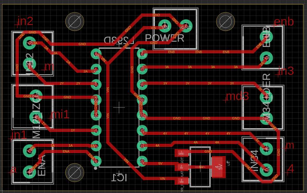
By knowing that it was possible to control the PWM with a dedicated pin (the ENA and ENB pins) I decided to change a bit of my main board with this third iteration and make the connection that was a Vcc one before, be another GPIO pin of the Pico. So I had 3 PIOs for each motor, making it 6 in total.
Same process went, and when I got to the testings with the motor driving program I had, which will be explained in the Embedded programming section, IT WAS FINALLY MOVING THE MOTORS!
I was super happy and started to work on other things after this essential part was finally done.
Power distribution
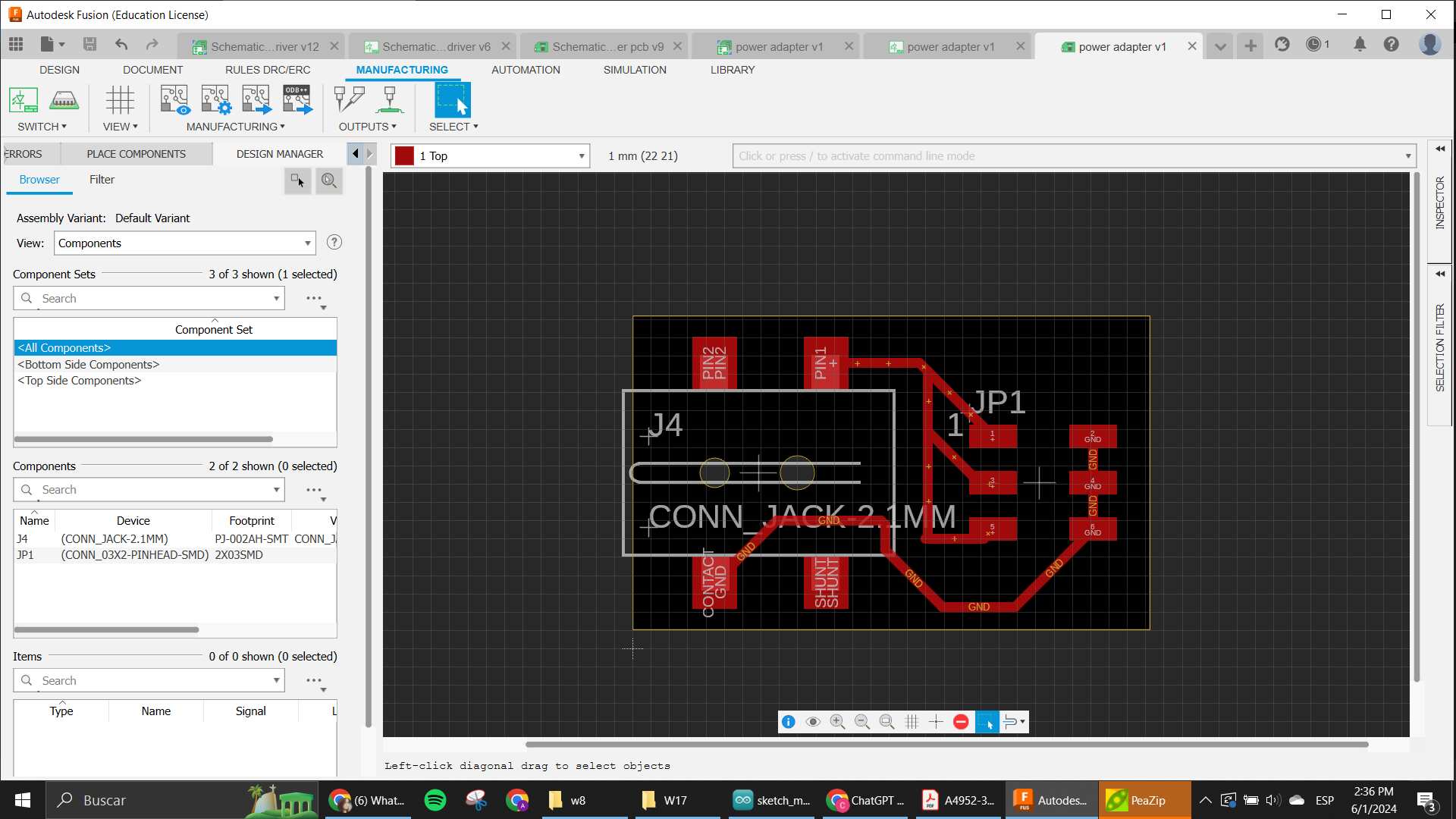
As I mentioned before, I have a little battery holder with 2 batteries that will be the power for all of the circuits.
The battery holder has an output of a little JACK that I had to find the way to separate into many sources. So I designed a little PCB that could basically hold the jack cable, and then have a connector with all the different positives and negatives that would go to each circuit that needed it.
This was a very easy pcb, but it was an important one to make the integration be possible.
Button Matrix
As you will read in the Embedded programming section, I had problems with my touchscreen that was my initial sensor planned for this whole project. So when it was almost time, I had to make a huge change to my ideas so I could actually have something that was meeting the criteria for it to be considered a Final Project.
I needed a way to make the user be able to interact with the motors and the screen, so the most obvious and easier way to make in very tight time was with buttons.
The basic idea for the buttons was to make the user interface that was supposed to go in the screen. Since I only wanted to create something that would help kids code very basic movements, I only needed 3 buttons for each action and one button for the "start". So that is basically what I designed here.
My main problem was that I really didn't want to change my main board again since that one was a very heavy order for the very tight time that I had. So in this iteration, since it wasn't really being used, I sacrificed my communications ports. I had 2 separated ports that I was planning on using for I2C and Serial communications for extra modules, that were completely ready to be used as GPIOs like I needed for my buttons. And there were exactly 4 ports that were ready, and I had 4 buttons. So it's almost on purpose and not just a coincidence really.
Since those where already pinheads, I needed to have some pinheads on the other side too, so I decided to make it also male headers and using female to female wires to connect both circuits, cause that way the connection was gonna be more secure (male wires are a little harder to keep on their place).
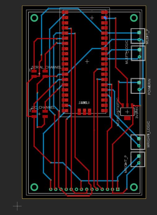
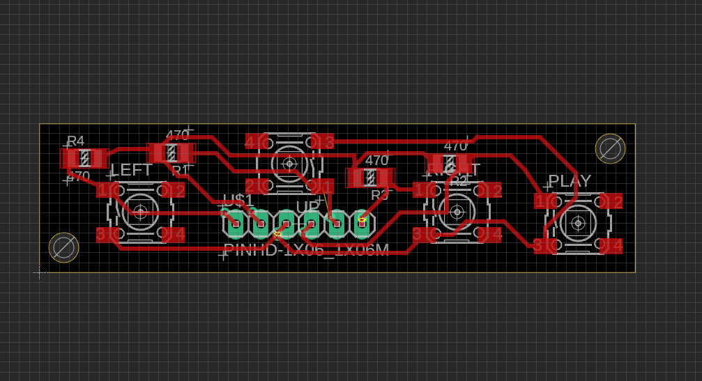
I prepared all the schematic and then went into the pcb to put the buttons already thinking on how I wanted the positions to go into the robot. I wanted the up button to be a little higher, the right on the right side and the left on the left side. I also knew I wanted the play button a little more on the bottom of the matrix, and that I didn't want it to be in the middle because I already had plans to put the Bluebo logo on the case, and I liked how it looked, so I had to make the matrix go near the front in a row.
After aligning everything and making all the routing, here is how the cute matrix looked like:
Embedded Programming
Motor Driver programming
The first thing I tested with programming was the motors, since I needed to have them moving before actually going into how to control them with the touchscreen. So as explained before, this was a very long process of going through 3 different chips that worked as h-bridges.
I tried to understand how to connect them and control them with ChatGPT helping me, I knew I wanted to use the Arduino IDE to do the whole thing since I have seen that it is way more reliable with the libraries and so. So I started to look into how to upload code with it into Raspberry, and apparently is very much the same as a XIAO, since both are controlled by an RP2040 chips.
Anyway, I went ahead and started a conversation about how to use each of the drivers I was testing with ChatGPT. Here you can read the whole thing.
In the conversation, it is seen that each program is very alike, since the logic is always mostly the same, what usually changes is the way the signals are sent. Sometimes the PWM is already built into the pins that control the direction, sometimes it needs the Enable pin to send that information in a different channel.
Its way more convenient to have the PWM already integrated to the direction pins too, since it reduces your need for one extra connection, but the Enable pin also helps you control the movement with more precision. So really depending on the application, you need to choose which is better. In my case, the important thing was to control the speed when the robot needed to turn, because I wasn't using any sensors to see the angle of the turn be exact. That is why in the final iteration you will see my program using only one motor moving to turn.
The basic idea is that you need to create functions for each type of movement where the pins are set to HIGH or LOW and if needed, with an analog value for PWM that will help control the speed of each motor. Also it is important to make both motors work simultaneously, so turning them both on, or both off is also to take into account into each function created.
At the end, the motor control section will be loaded into the main program, and as it was said before, the only time it actually worked well was with the L293D bridge. Here a little video of it working:
Touchscreen Programming
For this section, I went ahead and took inspiration from an example that I saw used the ILI screen too on youtube, I did some research to find out how to use this touchscreen cause I wanted a very interactive UI that could be used completely on the screen, this will allow me to make as many changes to the whole thing as I needed to make the project be expandable and grow with new modules if I wanted to make that happen, but as you will read, things didn't go as planned and many things had to be changed throughout the process.
At the end of the day, the programming was not exactly the problem, it probably was a hardware thing, which I unfortunately was not able to check because I only had one screen (which I tried to really protect cause it was the main part of the project lol). But here, a summarized explanation of what happened with my programming of this final project.
Inspiration and Analysis.
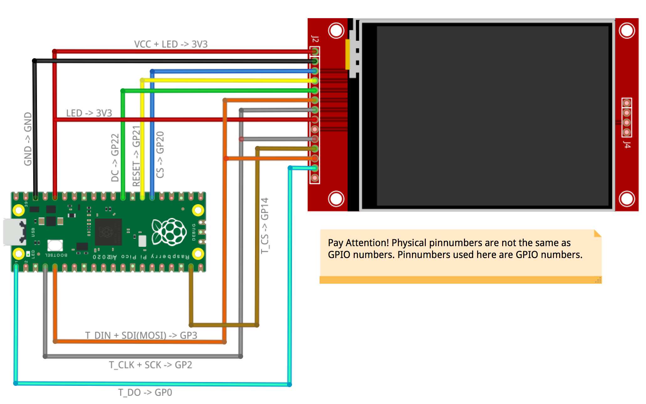
So like I said before, I found a tutorial on how to create a touchscreen matrix with the ILI9341 on youtube that I used as a base to create my project, actually, that is where I took the pinout from. So of course, I knew that the code was gonna go in that route as well for what the project needed to be. This is the link to the project on instructables.
I started by asking ChatGPT to explain to me the whole code to understand each section and what it did better. Which will later help me update it with what I needed for my application. The whole conversation used for this section is in this link you can follow along with the explanation given here of the thought process.
Basically, the code allows me to create a matrix with buttons and each button can be programmed to do something if I want to. The whole thing works with TFT_eSPI as a libraary for the connection between the Pico and the Screen, using the SPI bus as the main way to send the commands. The buttons are prepared with the Keyboard library and the calibration is done by using the FS library and LittleFS one. This allows the program to create a space inside the memory of the Pico to save the information needed as calibration and use it for the application.
Everything else is the logic to make the program work, you basically setup everything and create the display matrix, and then you create the functions that will control the buttons by reading what the touchscreen is sensing, which is all read as coordinates in x and y, and those values are enclosed inside a section of the screen that is where the button is. If you touch that section where the button is placed and the touchscreen senses it, it saves it in a variable that is used to activate what that specific button is supposed to do. You can completely customize this and create even newer matrix based on those buttons. That is the basis of the code.
Another important part of the code was the calibration section, which basically is a function that comes inside the TFT_eSPI library already, that helps you have more accurate readings with the touchscreen. You have a little arrow in each of the corners that helps you have the values of the touch reading saved to use as the limits of the screen.
Something else very important in this code and in using the TFT_eSPI library is the "Setup.h" file, in here is where you put the values of the ports and connections needed for the program to work, which basically connects the library to the parts that you need for each chip to work. In my case, the Setup file needed to have the ILI9341 driver, and have all the needed connections in specific ports that were connected to the Raspberry Pico as it was shown in the pinout from the tutorial.
All that info was loaded into the setup file and used for the program too.
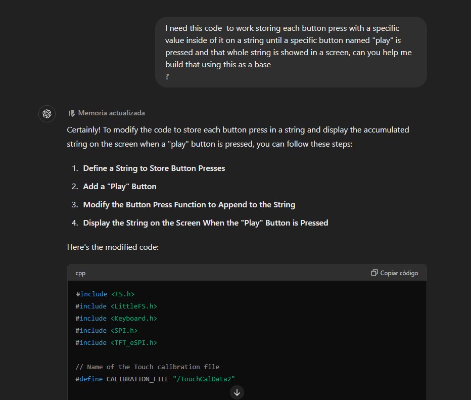
I started working on the program in ChatGPT, by basically asking the changes that I needed to implement for my application. One of them being that I wanted a concatenation of each button press stored in a variable, which would then activate things after the "play" button was pressed, basically making the stored values be revised again and each value activating something specific.
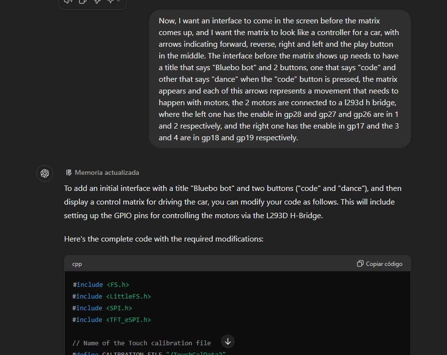
I also started already thinking of the UI matrix like the arrows section of a controller looks like, the starting screen with 2 modes too and asked to have that implemented. This part with the motors taken into account already, since at this point I already had the L293D pcb working for me. All of those changes where starting to become part of the program inside the ChatGPT conversation and I was looking and trying to understand all of the code that it was giving me to see if I needed to make changes. I was doing all of this while the pcb was being machined so I could test it after soldering. And to save time I was taking every bit and putting it into a draft in Arduino IDE to test it when I had the chance.
There were some things added to the program before being actually able to test it, until the time the pcb was ready and I could start with the demo of the whole code.
My first iteration for the program didn't work at all. The screen didn't even turn on, nothing was showing up, even tho apparently everything was right. I was pretty confused.
My mistake was to try and implement everything at once, because troubleshooting the code became a real nightmare to be honest.
Troubleshooting
So here is the deal, the part about making the touchscreen working, was actually pretty tiring. To make it short, I tried a lot of stuff. At the beggining, I realized that the first problem that I had was that the tutorial that I had was for a ILI9388 not the ILI9341, so the Setup.h was wrong because the driver was not for the chip I was using. But before actually realizing that, I even went to test the whole thing in MicroPython, but honestly working with external libraries in there is a little bit annoying, and even ChatGPT was getting confused with how to use the libraries. I understood that the chip for the touch section is a different one and that needs another library, but the one suggested by ChatGPT was deprecated and the other ones I found were with CircuitPython, so that made things pretty confusing. I only wanted to see something appear in the screen but nothing was working I started to fear that I broke my screen. Luckily it wasn't the case.
Like I said, in the Arduino version, the main problem was that I actually was using the wrong driver for the TFT_eSPI library cause I was not paying enough attention lol. When I changed the driver in the setup file at least something was starting to show up in the screen yay.
Now, the problem was the touchscreen, after the calibration section, which did work and allowed me to actually have something sensed with the screen, no button was working. And nothing appeared in the screen either.
I began to test the touch only, with a little program that I found in the Tft library folder as an example to see how the "getTouch" function worked and all.

In there I could actually see some values when I was testing it, like, the touch was "working" but the thing is that the coordinates that showed up where kind of not making any sense. The values were too big for the size of the screen, and I couldn't really understand the whole thing. I tried testing with other functions as well, and trying even with a different library, but to be honest, the thing wasn't working for me.
The main problem was that the values where out of the context of the scope, and another thing that started to happen later was that the calibration was being done "automatically", meaning, that it detected touching even when none was happening.
At this point, and after making many different approaches as it can be seen in the conversation with ChatGPT, I decided to change my sensing method, as it was apparent that most likely, the touchscreen part of the component was broken or malfunctioning.
At that point, it was the moment I went into the Button Matrix method. Were I used 4 physical buttons instead of the buttons appearing on screen to control the whole program.
A lot of the logic remained mostly the same, but at the end the "keyboard" library was not really used, there were just instructions in the screen not buttons that needed to be touched.
When the program began to actually work, it was when the details went into account.
For example, to have a more easier to understand look, there were "buttons" created by some rectangles that were defined beforehand to show the modes that were available.
Also, the logic for the use of the motors was slightly changed, as the way to read each state was not a char anymore, but a whole string with each movement so you could read the movement when the program was started. Colors were also shown in the screen when each button was pressed, representing the one that was pressed in that moment. And each had colors also implemented in them.
The "dance" mode was also created, which consisted in making the robot move in different random directions for 10 times and show variable colors as well, and at the end of the whole thing there was an "applause" section shown.
Little changes where made before the final version, mostly to have a nicer UI and having buttons that looked nice. Having the things be as centered as possible, having different sizes of letters where needed and also the timing for the movements after testing it. At the end, we got many functions that controlls the whole program effectively, with debounce of the buttons and a very responsive handling of them that allows the program to be pretty smooth.
System Integration
After everything, you can see how the interior of the project looks like here:
