Embedded Networking and Communications
-
Group assignment:
-
Send a message between two projects
-
Document your work to the group work page and reflect on your individual page what you learned
-
-
Individual assignment:
-
design, build and connect wired or wireless node(s) with network or bus addresses and a local interface
-
Navigation
-
Using a new micro: Attiny45
-
Deciding on a way to make the connections
-
Designing the board
-
Making the board
-
Programming the board
Using a new micro: Attiny45
So for this week we went to a different microcontroller from the XIAO because making a network requires many nodes, and basically we only have one XIAO per person available here. The solution we came up with was to finally test the tinys abilities and see how well we do on connecting them together via a bus.
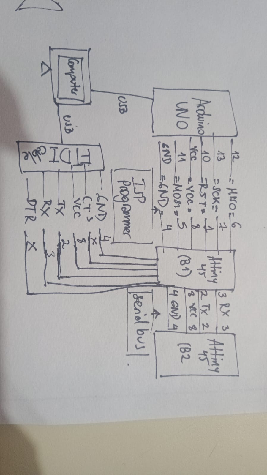
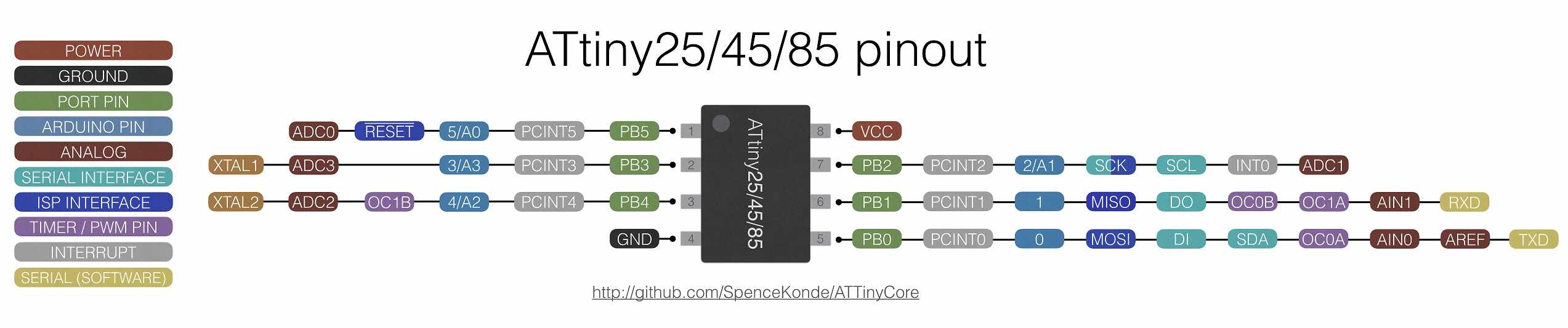
We had to find out how it works and see a bit of the pinout to create the circuit, and we did this in a group effort with our instructor Abdon.
Here is a picture of the pinout we used to help us and the final draft that helped us design the board.

Deciding on a way to make the connections
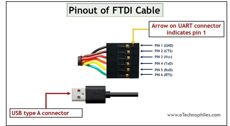
Here is where we had some new knowledge imparted. We wanted to test the simplest way to make the communications, so we went for a wired approach, since the wifi modules and bluetooth modules were not as available, and again, we only had access to one of the ESP XIAOs per person, it would be a little difficult to create a network wireless. But alas, the tinys can work with serial communication and it's pretty fast as well, and programming it wasn’t too daunting. In our design, we made a bus that is fully prepared to help us make the connections easily, with a serial bus (USART). There is also the FTDI that allows us to work with the computer itself.
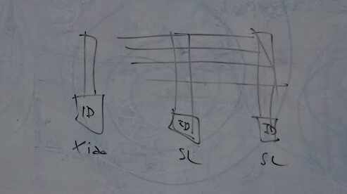
Now, how the bus works is quite simple actually, you just have one bus with all the nodes separated. The parts where the communication happens are thanks to the Tx (transmission) and Rx (receiver) lines, the other two, are power and ground respectively. Kinda like this:
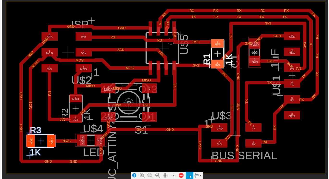
Designing the board
I have now mastered my ways in Fusion, cause I actually made this way faster than I thought I would. I basically copied the idea we had into the schematic, and then used Neil’s design of the hello45 board he made as a base for the pcb design. Ours had some different components like the button, but it still was super similar so the positions in mine are kinda like that as well.
The difference is that I made it with the autowiring and when it didn’t connect some parts is where I entered to fix those things. My paths were a little smaller than before, taking into account that the Attiny also has pretty small footprints so everything seemed to need a bit of an adjustment.
In the end, in the flatcam when I was preparing the gcode, this I felt made the isolation part a little more difficult because some sections were pretty small for the endmill to go into. I tried fixing it manually and I gave the cnc a go.
Here are some pictures of the process.


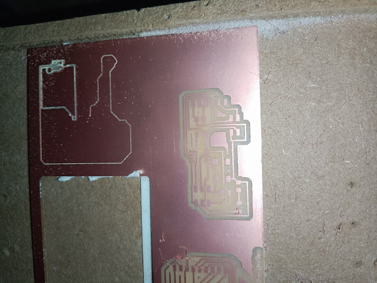
Making the board
As usual, I prepared my isolation and cut out of the board in the 1/64inch and 1/32inch end mills respectively, and it went pretty smoothly. As always, the main issue with the cnc is that the Z usually takes some tries to get inside the pcb but after fixing that part with some slow adjustments like we did in the production before. Another issue was that we were out of double sided tape, which was a little annoying but I went and bought some from the hardware store and we just lost like an hour and a half of time doing that 😣
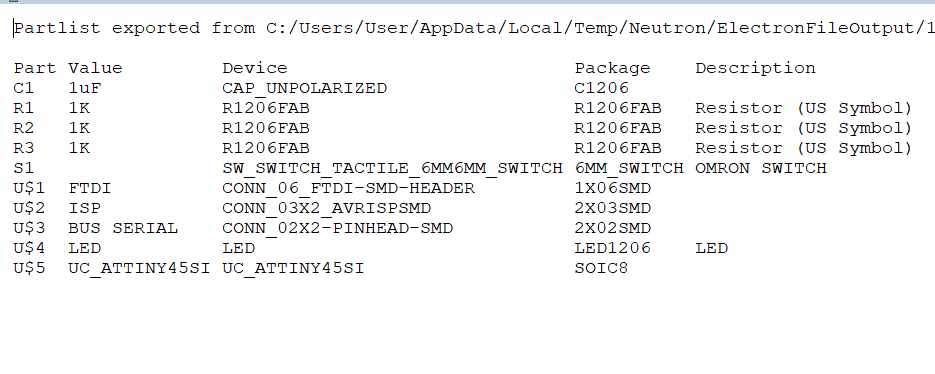
After machining was done, I went ahead and prepared the components that I would need for the board. Another daunting task, since I had issues before finding some of the connectors that we needed. I prepared a Bill of Materials in Fusion and have it here.
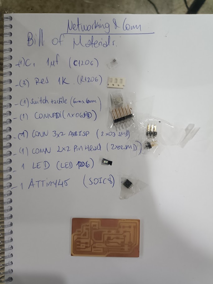
Went ahead and began looking into our deposit for all the parts I needed. Some of the connectors were not available anymore, so we had to do some scavenging into old projects and also I decided to cut some bigger ones into smaller pinout ones. Still, found everything I needed for 2 pcbs. Here is my helping list.
After finally having everything ready I started soldering the 2 boards. I am not too good with the soldering iron if I’m honest, especially when it comes to such small components. My vision is not the best so I make pretty stupid mistakes when I am soldering. One thing I noticed is that one section of my pcb was gonna cause me problems, since it had a short between 2 components. Thankfully it was an easy fix that I just could make the separation manually with an exacto knife and it would work. But well, I finished and here is a picture of how it looked for me.
*pic of my finished board
Programming the board
This was another new thing since we haven’t really used the Attiny before, we put the ISP connection for us to be able to use the ATMEL programmer available in the lab. Basically, using the old version of the Arduino IDE, you gotta prepare your environment to help you have the Attiny programming available and that is inside this page: I also followed a bit of the tutorial that my instructor did in one of his assignments. This is also the program that I wanted to test in my board, only without the motor section, basically making a blink led that will turn on with the command sent via serial.
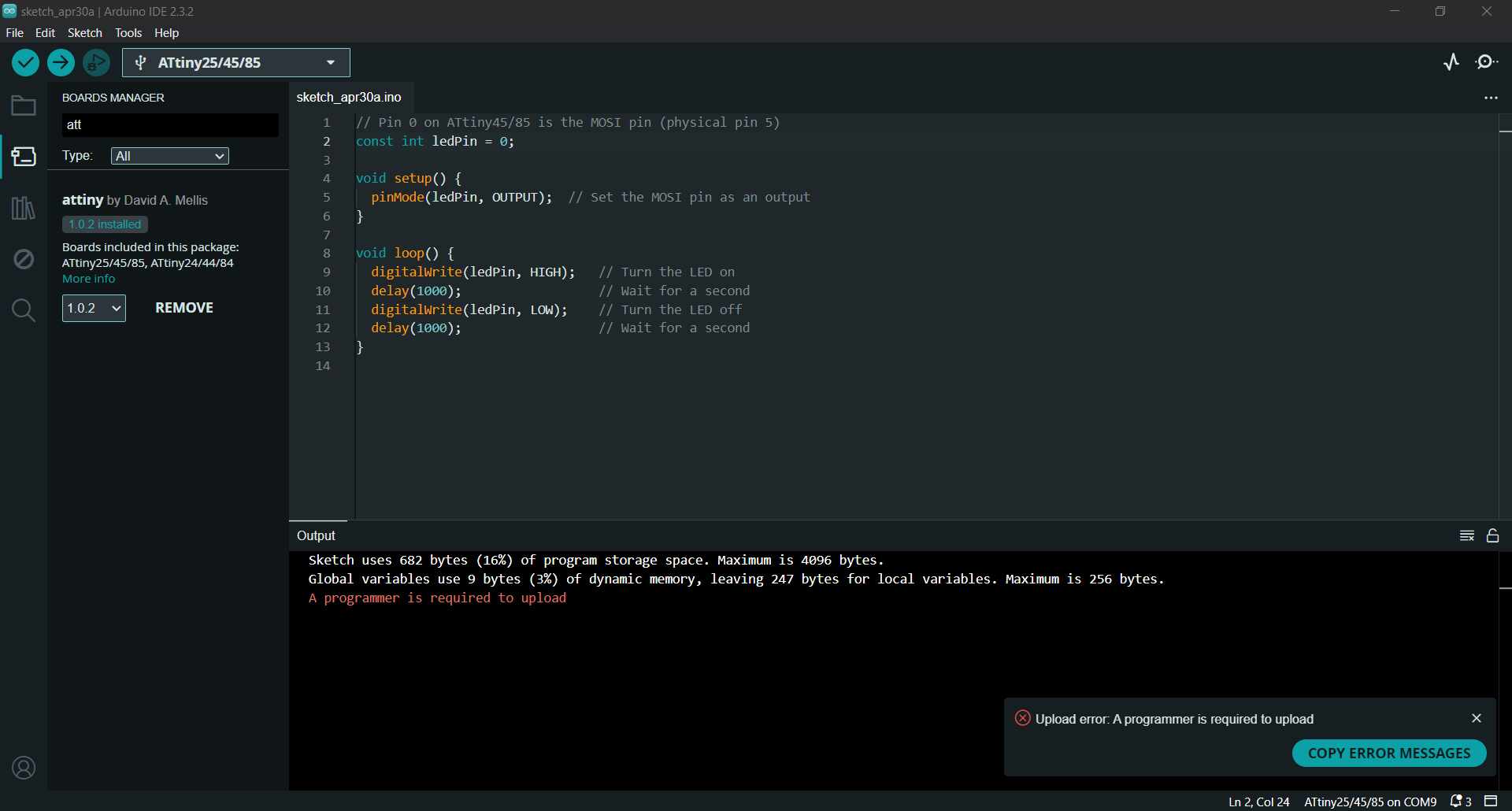
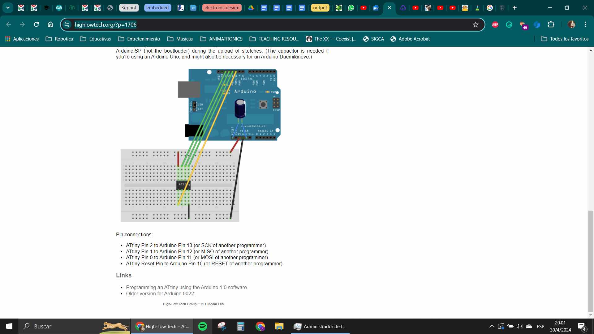
For some reason, it wasn’t working for me. I kept getting an error when I was trying to upload it with Atmel, so we started troubleshooting. I was unsure how it worked anyway, and my instructor said that maybe the problem was in the ATmel itself. Since I also had my Arduino available and we knew that was the most common way to program the Attinys, we tried to go that route. I started looking into tutorials and to see how it would work. At the end: this page really helped with the pinout for the arduino https://highlowtech.org/?p=1706
After that, it was basically making the arduino as an ISP programmer. And after loading that program, connect the Attiny with the guide in the page.
My instructor also went ahead and helped me with my soldering because he thought the problem could be some bad connection in the board, and he was right because after he went back with some more soldering tin, the board worked in my end!
I could finally program it, and tested the serial connection as well.
Here is the program for the Attinys, one of them is turned on with the 1 and off with a 0, and the other is on with 2 and off with 3. We also made the bus for them to be all connected at once and added another node in case I decided to test it with my Xiao as well. In the end, the bus idea worked and the serial communication was a success.
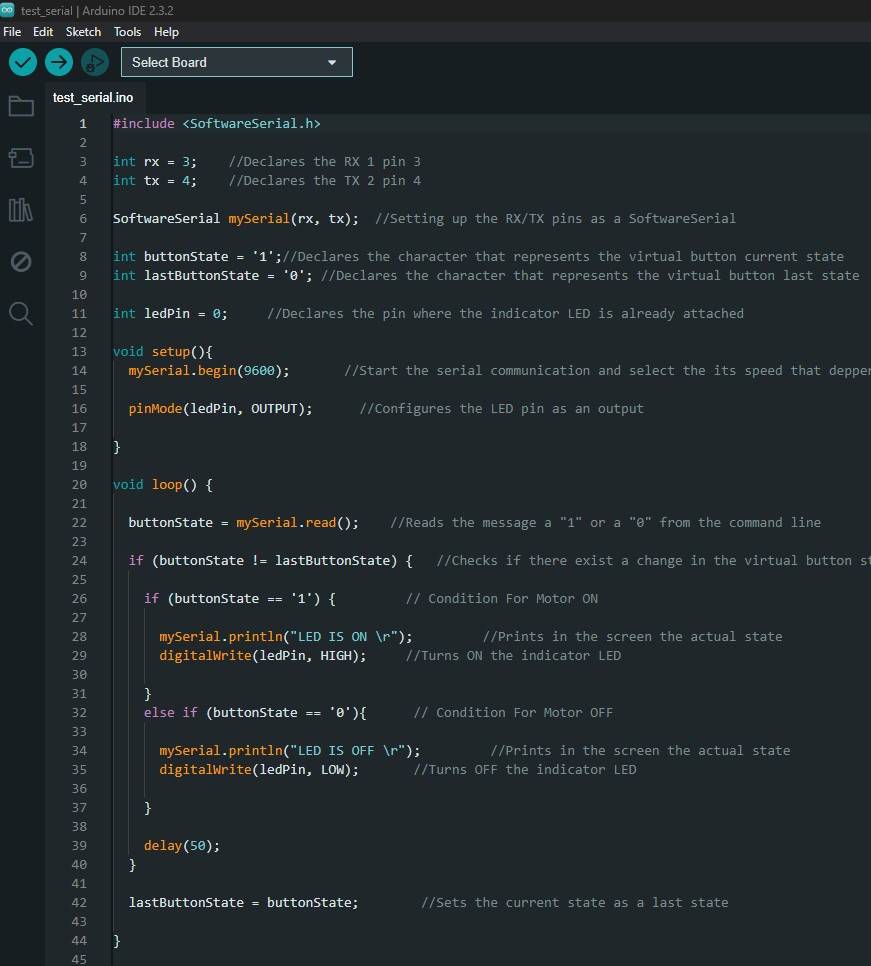
So basically I used the ISP programming protocol of the Arduino to make the programming of both boards, and left it connected in case I wanted to make changes to the program. The communication was done via a Serial bus, where the Tx and Rx cables sent the signals between boards, and one of them was connected to the computer via FTDI cable wich is where the serial monitor with the commands was in. You can see a little diagram explaining this here: