11. Input devices
This week I worked on defining my final project idea and started to getting used to the documentation process.
Assignments in this week
Group Assignment:
- [x] probe an input device’s analog levels and digital signals
Individual assignment:
- [ ] measure something: add a sensor to a microcontroller board that you have designed and read it
Group Assignment
This part was completed after I completed my personal assignment.
Since we have already learned the data transmission format and method of DHT11 sensor. I found the memory in the laboratory and observed the following results by connecting the X1 of the memory to the GND of the board and the signal terminal SIG of DHT11 respectively.
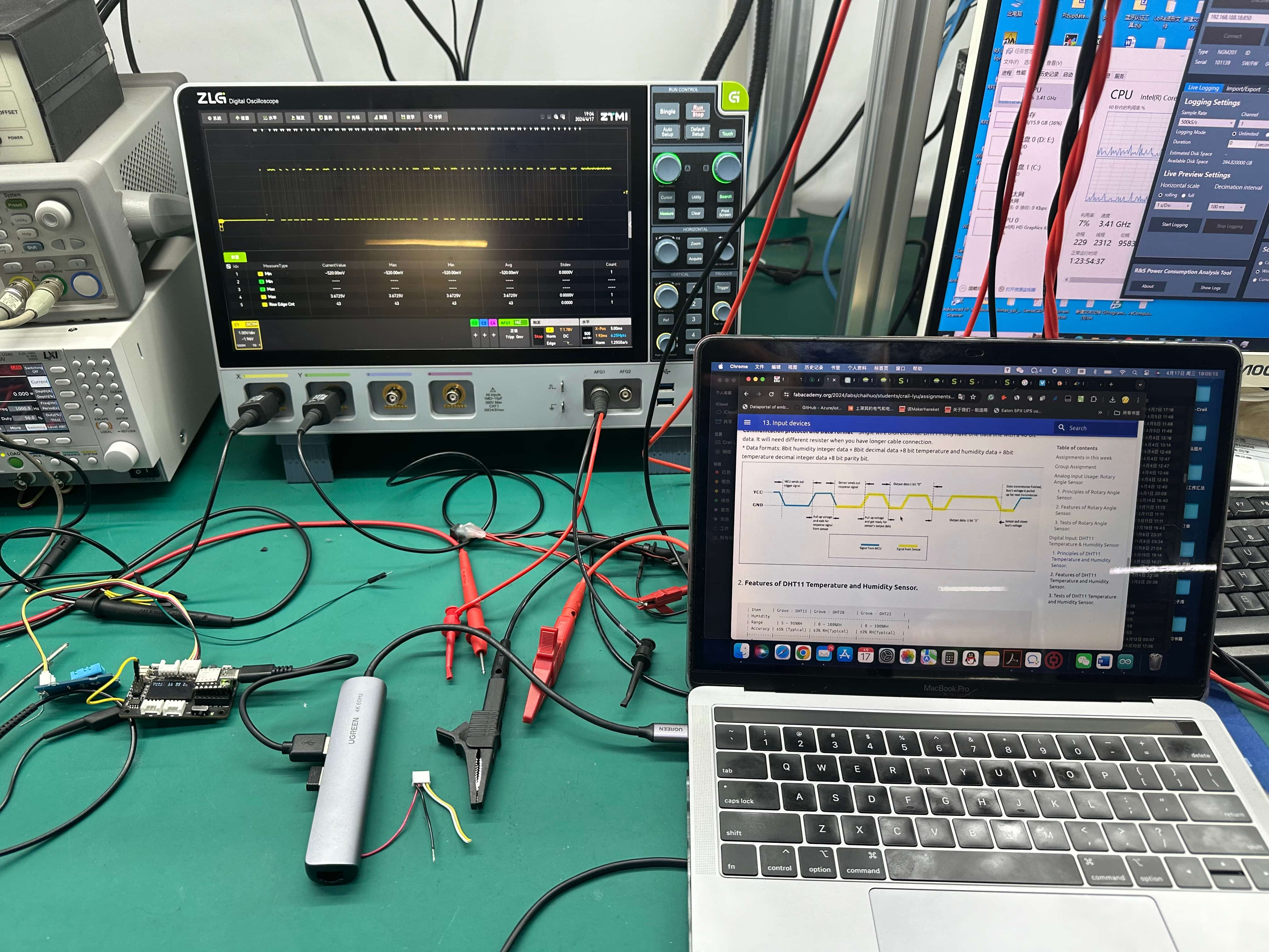

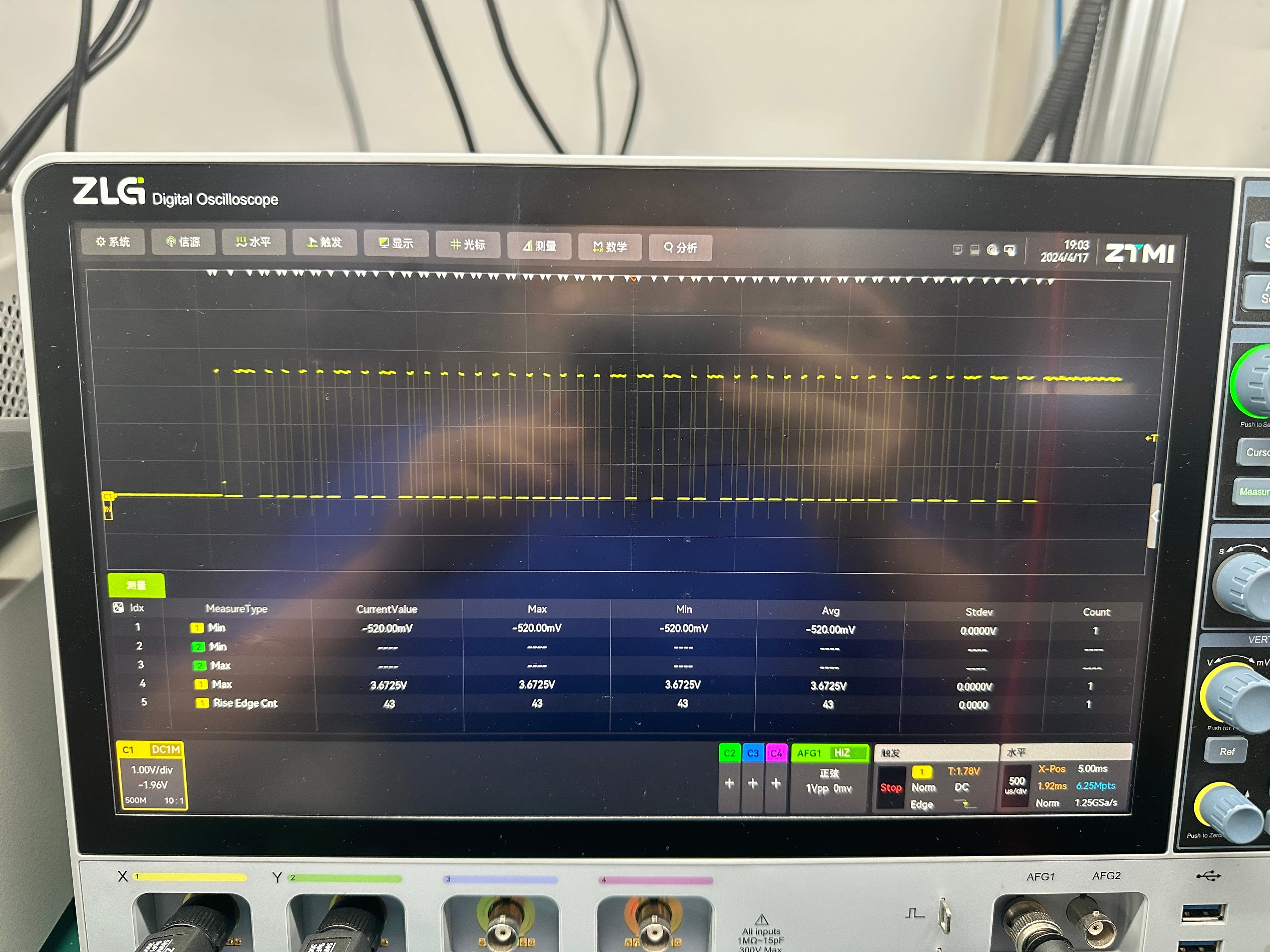 Through observation with the oscilloscope, I clearly saw that there are 43 level changes in the picture. According to the description in the datasheet of DHT11, after the initialization level of a part of the MCU, it is the data bit signal of DHT11.

Analog Input Usage: Rotary Angle Sensor
1. Principles of Rotary Angle Sensor.
By using ChatGPT,I got the following answers.
Rotary angle sensors, also known as potentiometers or angle transducers, work based on the principle of variable resistance. Here’s how they typically function:
A. Rotational Movement: These sensors are designed to measure the angular position or rotation of an object. As the object rotates, the sensor detects this movement.
B. Variable Resistance: Inside the rotary angle sensor, there is a resistive element. This element is typically a thin strip of resistive material. As the sensor rotates, the wiper (a conductive element) moves along this resistive strip.
C. Voltage Divider: The resistive strip acts as one part of a voltage divider circuit. The wiper, which moves along the strip, divides the voltage between the input and output terminals of the sensor.
D. Output Voltage: The position of the wiper along the resistive strip determines the resistance between the input and output terminals, thereby determining the output voltage of the sensor. This output voltage is typically proportional to the angular position of the sensor.
E. Measurement: By measuring the output voltage, the angular position or rotation of the sensor can be determined. This measurement is often converted into a digital signal for further processing or display.
Overall, rotary angle sensors provide a simple and effective way to measure angular position in various applications, such as robotics, automotive systems, industrial machinery, and consumer electronics.
2. Features of Rotary Angle Sensor.
The rotary angle sensor I took this time is actually a large rotating resistor. I measured it with a voltmeter and found that the resistance value is about 10K ohms. Its main working principle is to obtain different resistance value distribution by rotating the knobs at different positions, so that the output voltage signals are different.
  | Item         | Min  | Typical   | Max  | Unit |
  |--------------|------|-----------|------|------|
  | Voltage      | 4.75 | 5.0       | 5.25 | VDC  |
  | Rotary Angle | 0    | /         | 300  | Deg  |
  | Dimension    | /    | 19*19*30.1| /    | mm   |

3. Tests of Rotary Angle Sensor.
First, I used a voltmeter to actually measure the output resistance value of the module. By rotating it, I found that the maximum resistance value was 11.62 KΩ and the minimum resistance value was 0.04 KΩ.
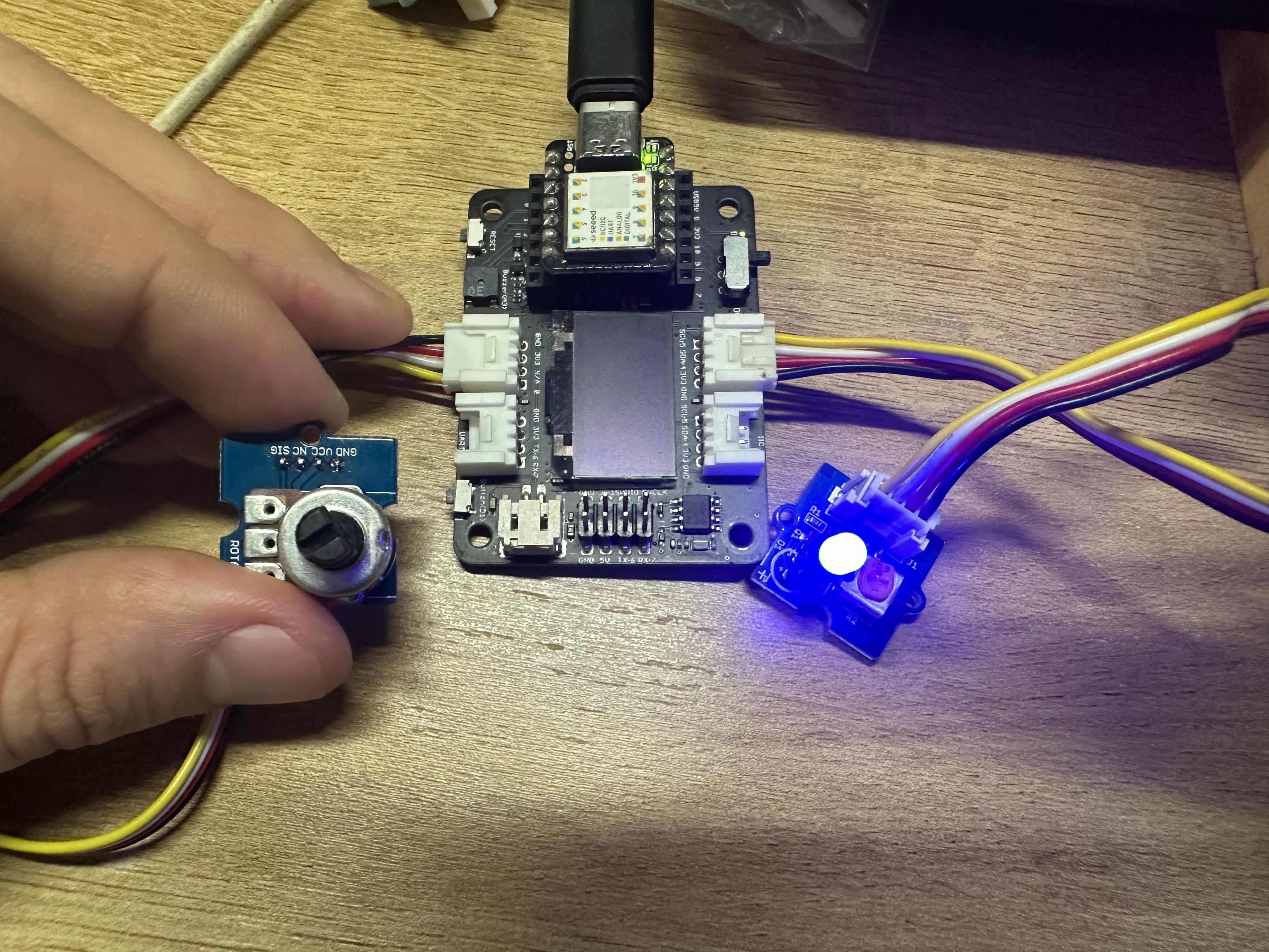
Secondly, I connected the module to the A0/D0 interface of XIAO SAMD21, and at the same time connected an LED module to the IIC interface, and wrote the following program through ChatGPT.
/*macro definitions of Rotary angle sensor and LED pin*/
#define ROTARY_ANGLE_SENSOR A0
#define LED 5  //the Grove - LED is connected to PWM pin D3 of Arduino
#define ADC_REF 5 //reference voltage of ADC is 5v.If the Vcc switch on the seeeduino
                    //board switches to 3V3, the ADC_REF should be 3.3
#define GROVE_VCC 5 //VCC of the grove interface is normally 5v
#define FULL_ANGLE 300 //full value of the rotary angle is 300 degrees

void setup()
{
    Serial.begin(9600);
    pinMode(ROTARY_ANGLE_SENSOR, INPUT);
    pinMode(LED,OUTPUT);
}

void loop()
{
    float voltage;
    int sensor_value = analogRead(ROTARY_ANGLE_SENSOR);
    voltage = (float)sensor_value*ADC_REF/1023;
    float degrees = (voltage*FULL_ANGLE)/GROVE_VCC;
    Serial.println("The angle between the mark and the starting position:");
    Serial.println(degrees);

    int brightness;
    brightness = map(degrees, 0, FULL_ANGLE, 0, 255);
    analogWrite(LED,brightness);
    delay(500);
}
Finally, by rotating and twisting the rotary angle sensor, we can see that the brightness of the LED lamp post changes accordingly.
Digital Input: DHT11 Temperature & Humidity Sensor
1. Principles of DHT11 Temperature and Humidity Sensor.
The DHT11 sensor detects temperature and humidity using two main components: a capacitive humidity sensor and a thermistor.
A. Capacitive Humidity Sensor:
* The capacitive humidity sensor measures humidity levels by detecting changes in capacitance.
* It consists of a moisture-sensitive capacitor made of a polymer material.
* When exposed to air, this material absorbs or releases water molecules, causing the capacitance of the sensor to change.
* The sensor then converts this change in capacitance into an electrical signal, which is processed to determine the relative humidity.
B. Thermistor for Temperature Sensing:
* The DHT11 sensor includes a thermistor, which measures temperature by sensing changes in electrical resistance.
* The thermistor is typically made of a semiconductor material whose resistance decreases as temperature increases.
* As the ambient temperature changes, the resistance of the thermistor changes accordingly.
* The DHT11 measures this resistance and converts it into a corresponding temperature reading.
In summary, the DHT11 sensor employs a capacitive humidity sensor to measure humidity levels based on changes in capacitance caused by moisture absorption or release, and it uses a thermistor to measure temperature by detecting changes in electrical resistance. These two measurements are then processed and converted into digital signals for output.
The humidity sensing component has two electrodes with a moisture-holding substrate (usually a salt or conductive plastic polymer) in between. As the humidity rises, the substrate absorbs water vapor, resulting in the release of ions and a decrease in the resistance between the two electrodes. This change in resistance is proportional to the humidity, which can be measured to estimate relative humidity.
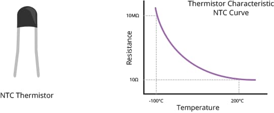
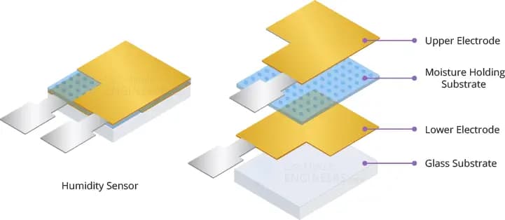 The sensor also includes a NTC thermistor for measuring temperature. A thermistor is a type of resistor whose resistance varies with temperature.
Technically, all resistors are thermistors in the sense that their resistance changes slightly with temperature, but the change is typically very small and difficult to measure.
Thermistors are designed so that their resistance changes dramatically with temperature (by 100 ohms or more per degree). The term “NTC” stands for “Negative Temperature Coefficient,” which means that resistance decreases as temperature rises.
Parameters:
Relative Humidity
Resolution:16Bit
Repeatability:±1%RH
Accuracy:25℃ ±5%RH
Interchangeability:Fully interchangeable
Response time:1/e (63%)25℃ 6s
1m/s Air 6s
Hysteresis:<±0.3%RH
Long-term stability:<±0.5%RH/yr
Temperature
Resolution:16Bit
Repeatability:±1℃
Accuracy:25℃ ±2℃
Response time:1/e (63%) 10S
Electrical Characteristics
Power supply:DC 3.3~5.5V
Supply current:Measure 0.3mA Standby 60μA
Sampling period:Secondary Greater than 2 seconds
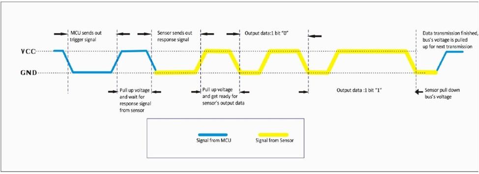
Communication protocol and Data format
* Single wire bidirectional: DHT11 only have one data line with a 40-bit data. It will need different resister when you have longer cable connection.
* Data formats: 8bit humidity integer data + 8bit decimal data +8 bit temperature and humidity data + 8bit temperature decimal integer data +8 bit parity bit.
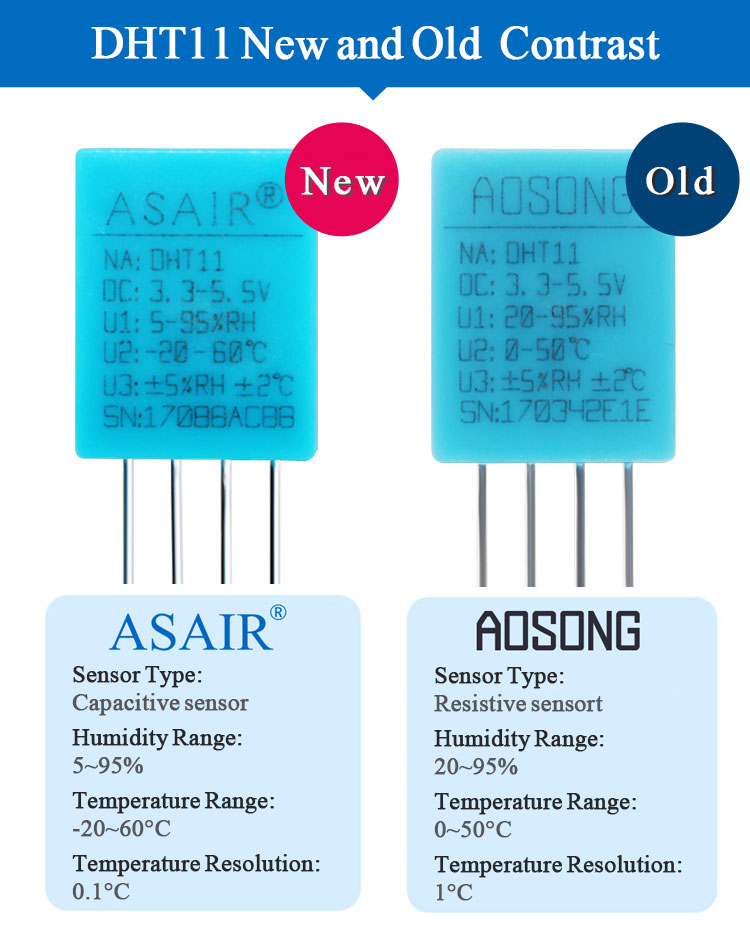
2. Features of DHT11 Temperature and Humidity Sensor.
  | Item     | Grove - DHT11 | Grove - DHT20     | Grove - DHT22     |
  | Humidity    -------------------------------------------------------|
  | Range      | 5 ~ 95%RH     | 0 ~ 100%RH        | 0 ~ 100%RH        |
  | Accuracy | ±5% (Typical) | ±3% RH(Typical)   | ±2% RH(Typical)   |
  |----------|---------------|-------------------|-------------------|
  | Temperature ---------------------------------------------------- |
  | Range      | -20 ~ 60℃     | -40 ~ 80 ℃        | -40 ~ 80 ℃        |
  | Accuracy | ±2% (Typical) | ±0.5% RH(Typical) | ±0.5% RH(Typical) |
3. Tests of DHT11 Temperature and Humidity Sensor.
First, I connect the DHT11 sensor to the interface of D0, and then output the following program.
// Example testing sketch for various DHT humidity/temperature sensors
#include <Arduino.h>
#include <U8x8lib.h>
#include <Wire.h>
#include "Grove_Temperature_And_Humidity_Sensor.h"
U8X8_SSD1306_128X64_NONAME_HW_I2C u8x8(/* clock=*/ PIN_WIRE_SCL, /* data=*/ PIN_WIRE_SDA, /* reset=*/ U8X8_PIN_NONE);   // OLEDs without Reset of the Display
// Uncomment whatever type you're using!
#define DHTTYPE DHT11   // DHT 11

/*Notice: The DHT10 and DHT20 is different from other DHT* sensor ,it uses i2c interface rather than one wire*/
/*So it doesn't require a pin.*/
#define DHTPIN 0     // what pin we're connected to(DHT10 and DHT20 don't need define it)
DHT dht(DHTPIN, DHTTYPE);   //   DHT11 DHT21 DHT22

void setup() {
    u8x8.begin();
    u8x8.setFlipMode(1);   // set number from 1 to 3, the screen word will rotary 180
    Serial.begin(115200);
    Serial.println("DHTxx test!");
    Wire.begin();

    /*if using WIO link,must pull up the power pin.*/
    // pinMode(PIN_GROVE_POWER, OUTPUT);
    // digitalWrite(PIN_GROVE_POWER, 1);
    dht.begin();
}

void loop() {
    float temp_hum_val[2] = {0};
    // Reading temperature or humidity takes about 250 milliseconds!
    // Sensor readings may also be up to 2 seconds 'old' (its a very slow sensor)
    u8x8.setFont(u8x8_font_chroma48medium8_r);
    u8x8.setCursor(0, 0);

    if (!dht.readTempAndHumidity(temp_hum_val)) {
        Serial.print("Humi: ");
        Serial.print(temp_hum_val[0]);
        Serial.print(" %\t");
        Serial.print("Temp: ");
        Serial.print(temp_hum_val[1]);
        Serial.println(" *C");

        u8x8.print("Humi: ");
        u8x8.print(temp_hum_val[0]);
        u8x8.println(" %\t");
        u8x8.print("Temp: ");
        u8x8.print(temp_hum_val[1]);
        u8x8.println(" *C");

    } else {
        Serial.println("Failed to get temprature and humidity value.");
        u8x8.print("Failed to get temprature and humidity value.");
    }
    delay(1500);
}
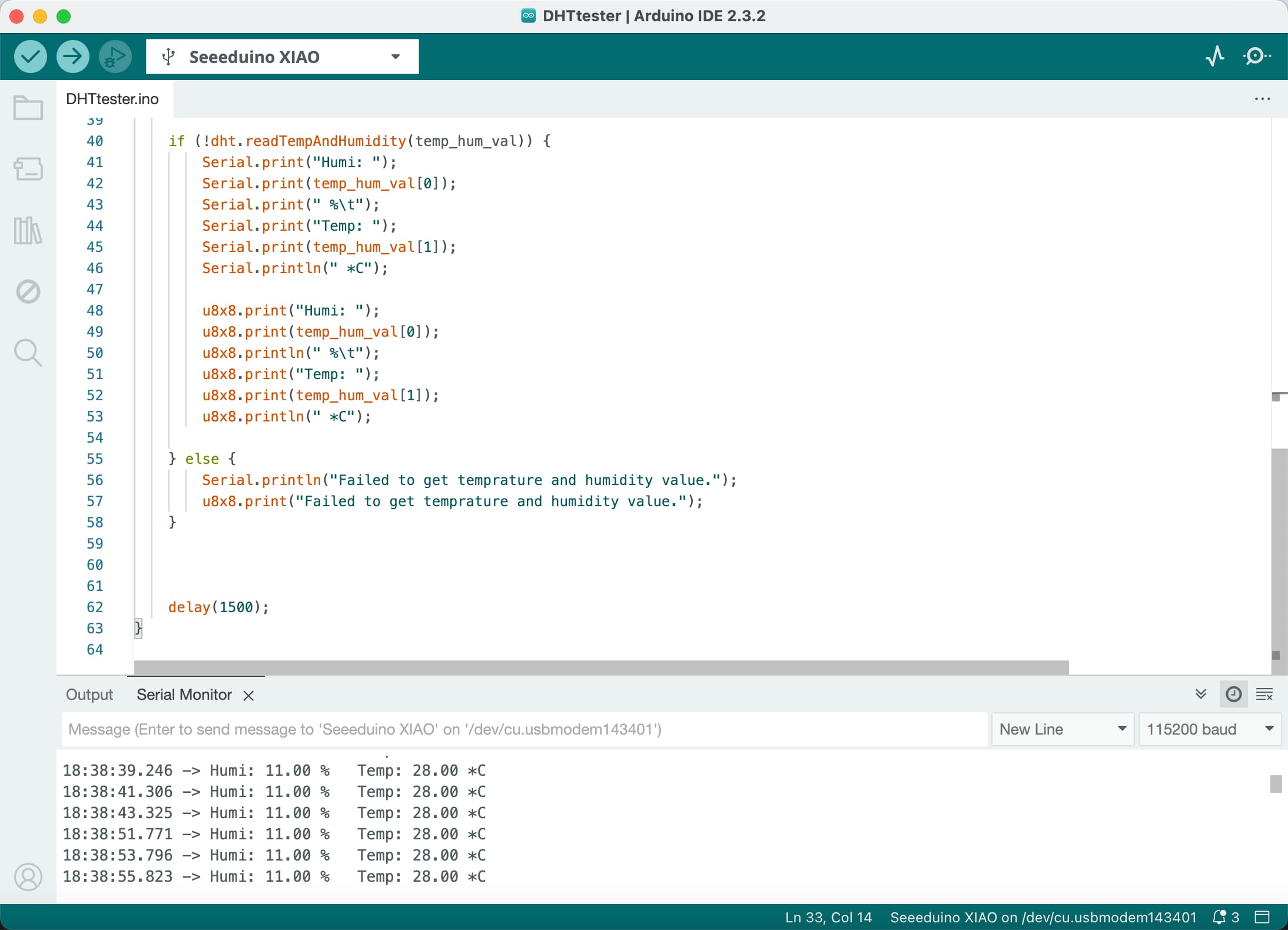
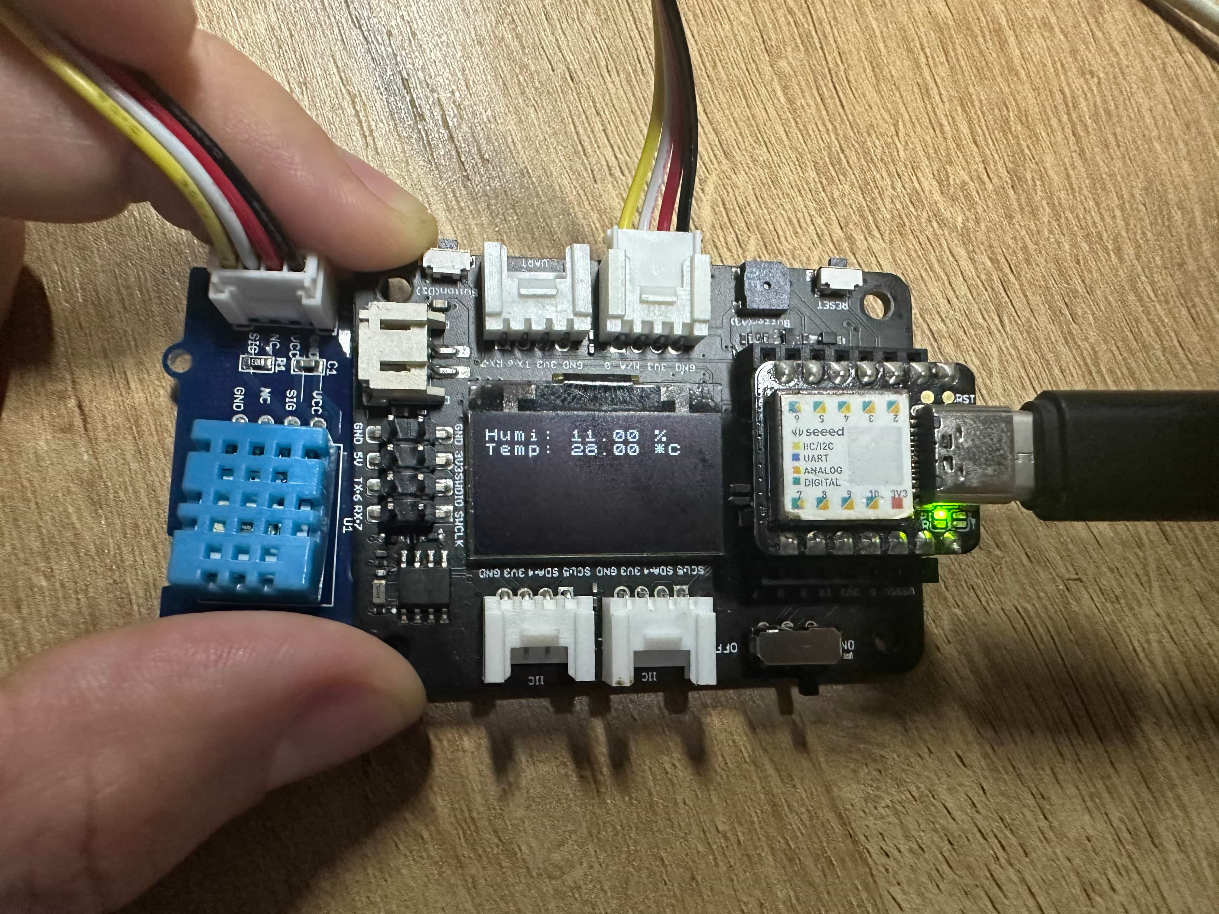 Finally I saw the sensor readings from both the serial monitor and the OLED display.
Input Design and prctice.
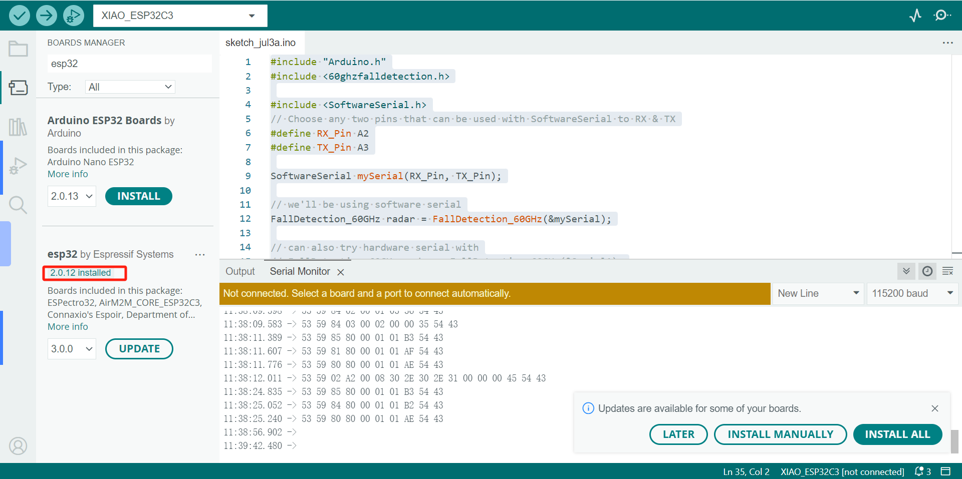
In this part, I go straight to designing my final project. Since I have decided to use mmWave as a sensor, I need to understand and be familiar with the related functions of this sensor, and design and manufacture my circuit board.
Project Report: Schematic & PCB Design Journey
Schematic & PCB Design using KiCad
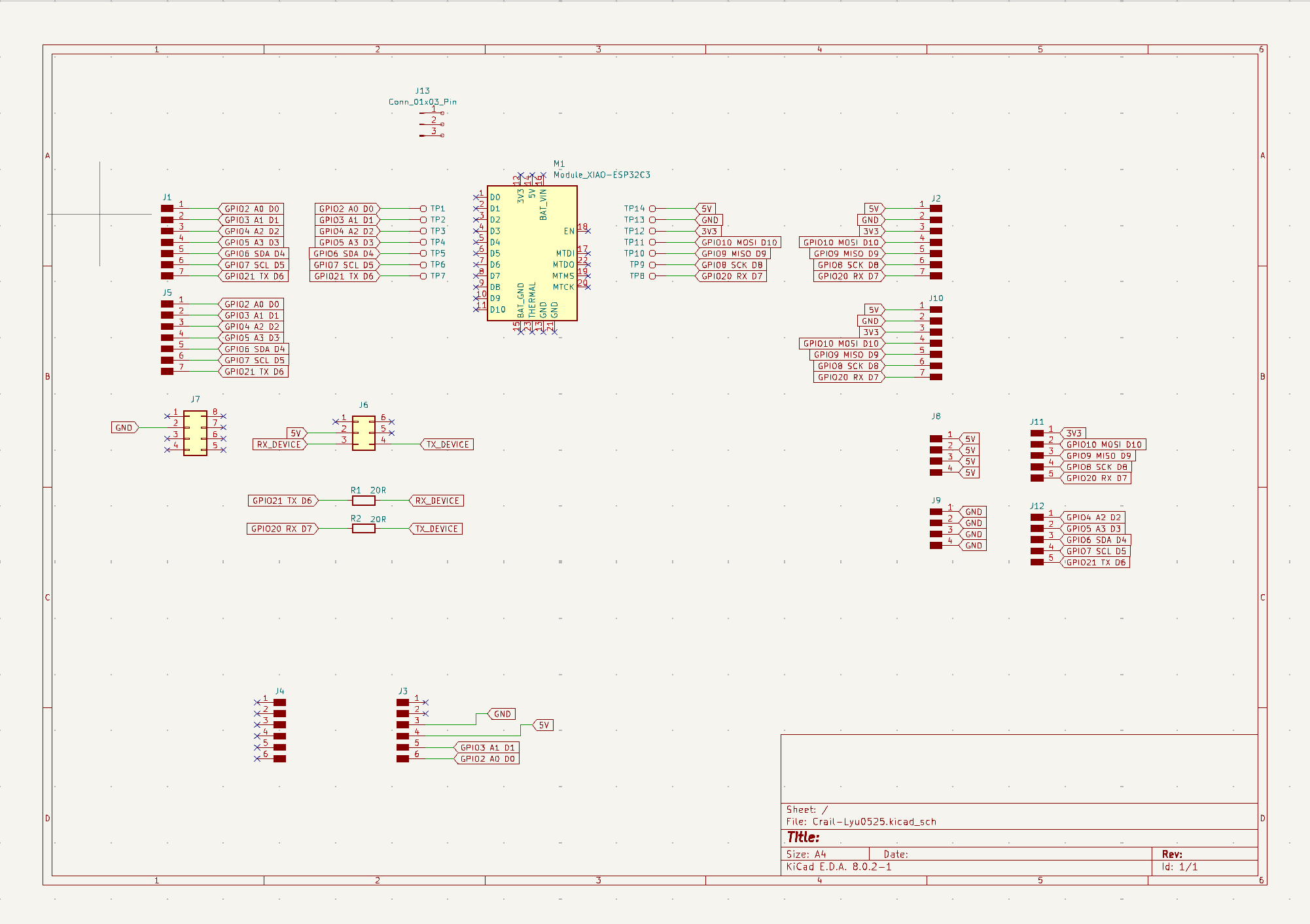
In my project, I used KiCad for both schematic and PCB design. For the schematic, I employed a modular approach and marked connections for easier future modifications and inspections. This careful planning is crucial for the final project phase.
Download my Schematic Design: Schematic Design
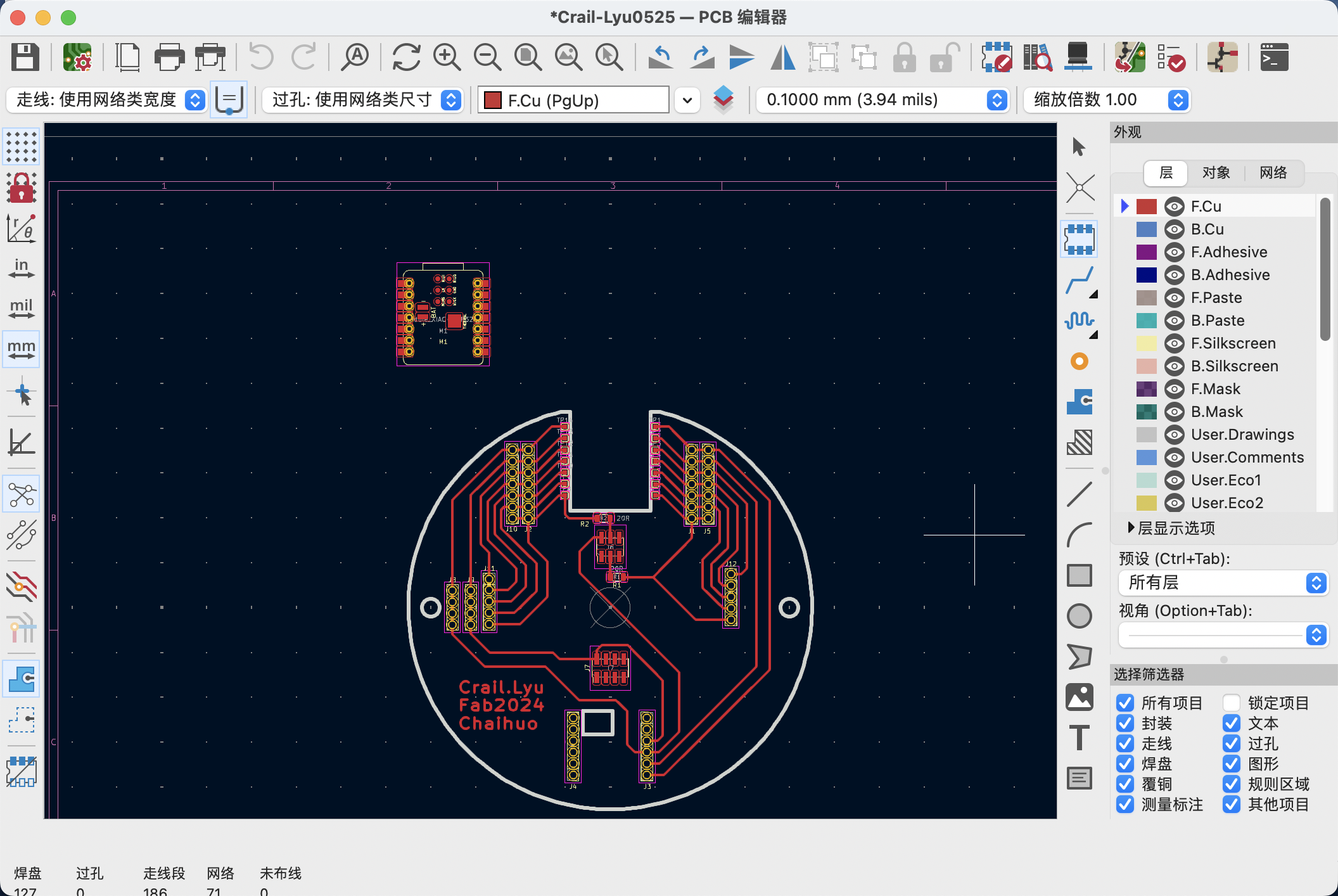
Challenges in PCB Design
In PCB design, I faced challenges due to using a makerspace CNC machine that requires all traces on a single layer. This constraint made component placement tricky, especially ensuring adequate space for components like the XIAO board.
Download my PCB Design: PCB Design
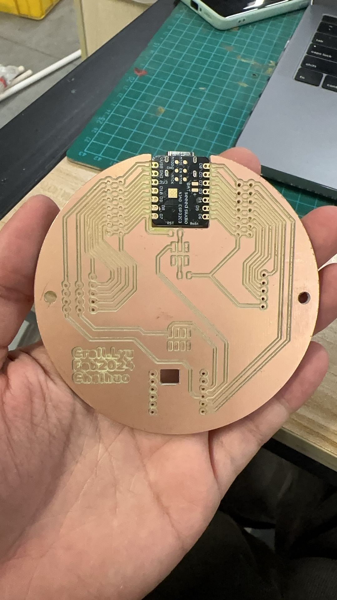
Manufacturing the Boards
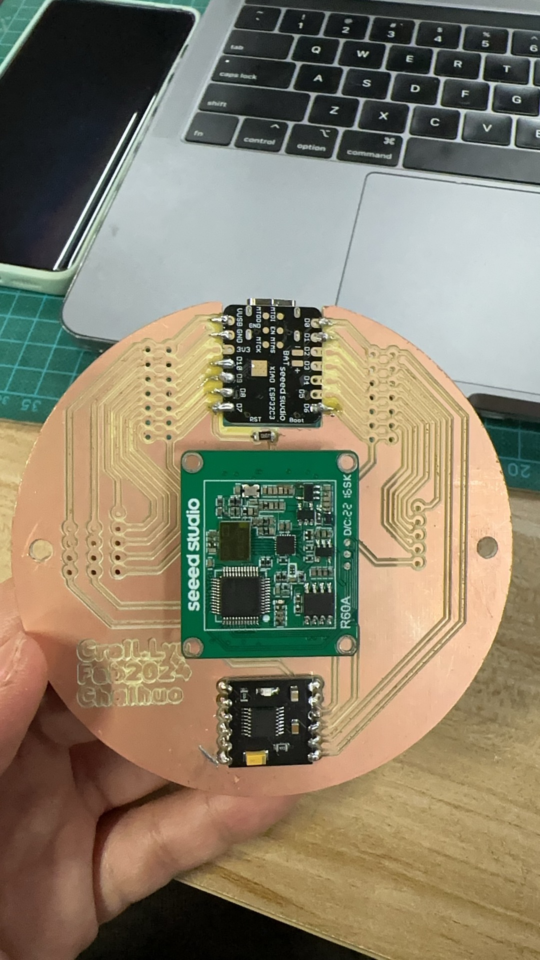
After design, I proceeded to manufacture the circuit board. Here’s the final result:
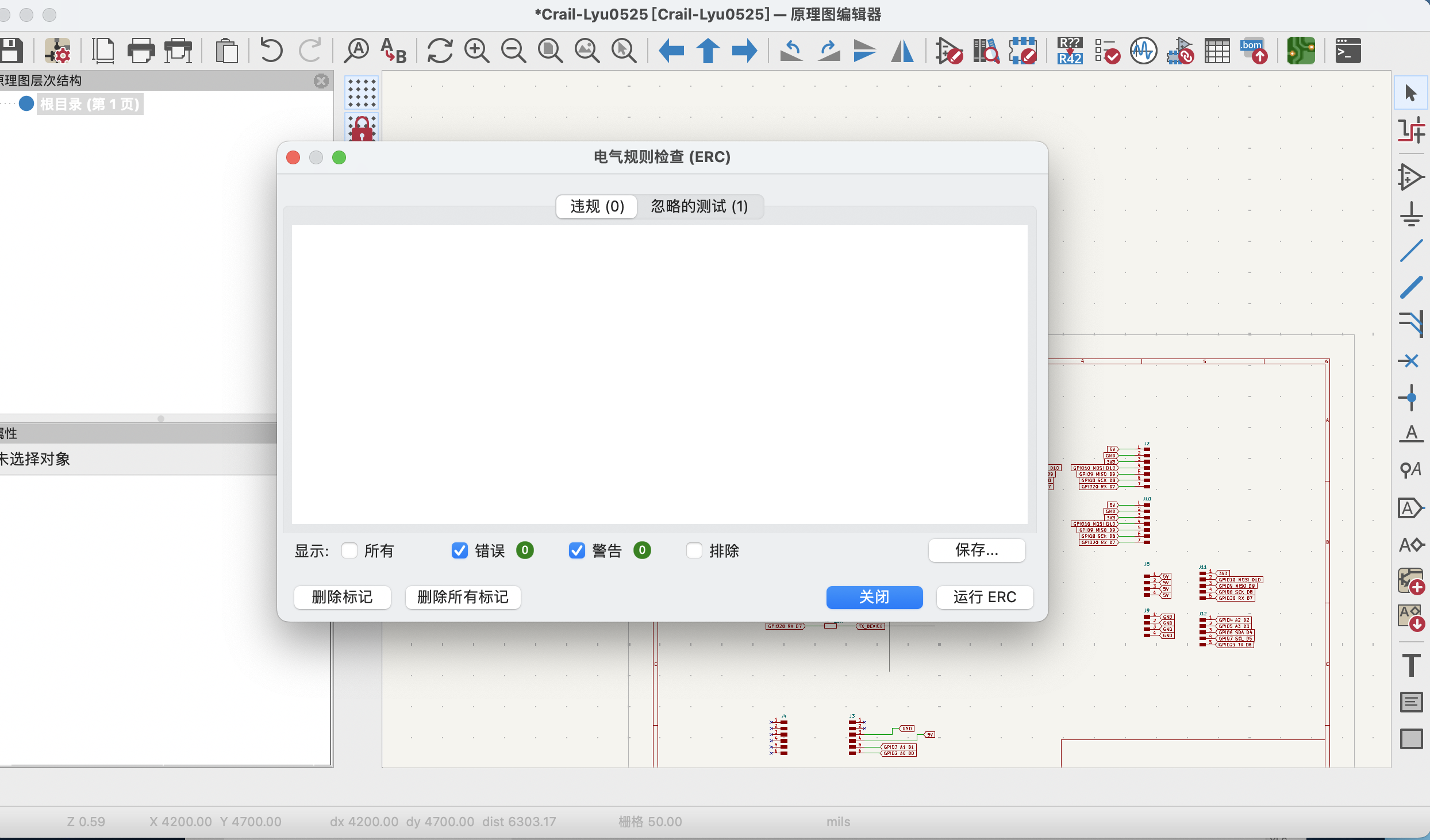
Simulation and Testing
I did not simulate the board’s functions virtually, relying instead on design rule checks (ERC) which showed no faults initially.
Learning from Mistakes
However, I encountered a critical design error during testing. Without thorough simulation, I mistakenly connected the RX and TX interfaces of the main sensor incorrectly to the XIAO board. This oversight required additional work, including using jumper wires and seeking mentorship to correct the issue.
Corrected Design:
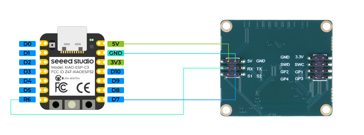
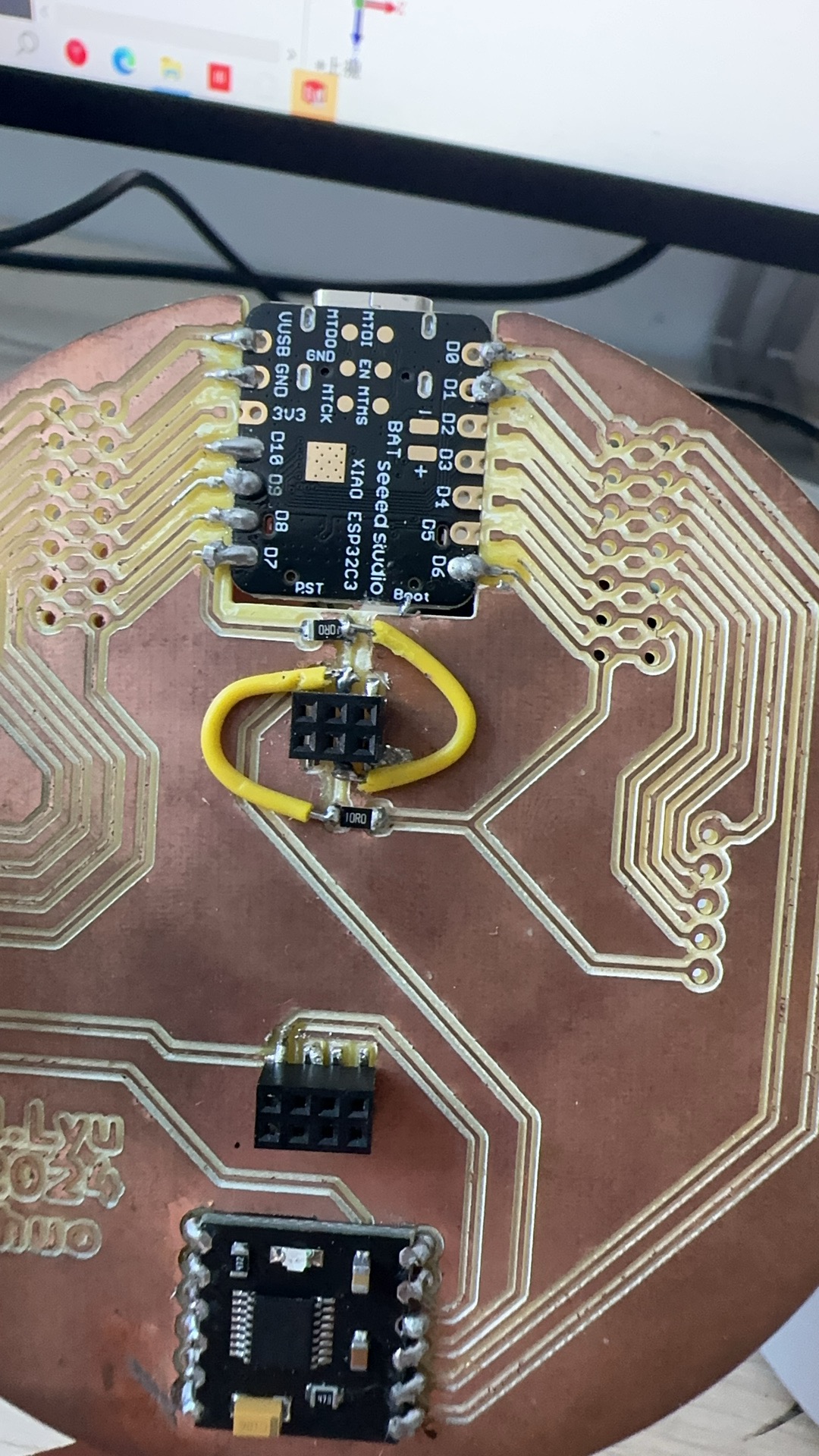
With guidance, I resolved the connection issue using jumper wires:
Final Testing and Results
This section has several metrics that can evaluate the input sensor results.
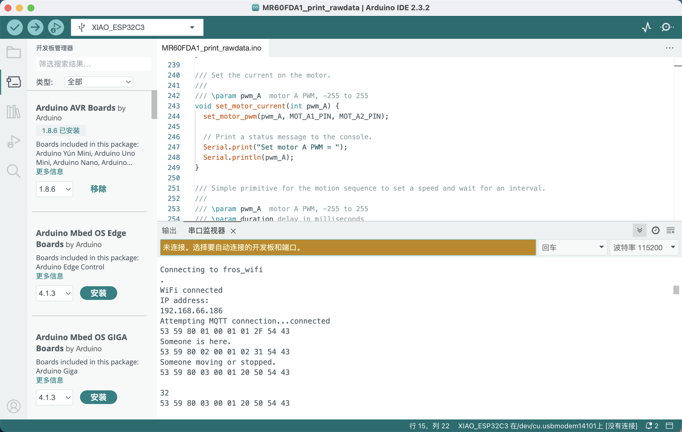
1. Read the mmWave sensor data results from the serial monitor of Arduino IDE.
a. Real-time monitoring results of sensor raw data.
b. The sensor detects the monitoring results of someone passing by/staying/falling.
2. Use LED lights to represent mmWave real-time data results.
a. When the sensor is monitoring, the LED light ring lights up green.
b. When someone passes by/stays/falls, the monitoring results of the sensor will be reminded by the color change of the yellow/red LED light.
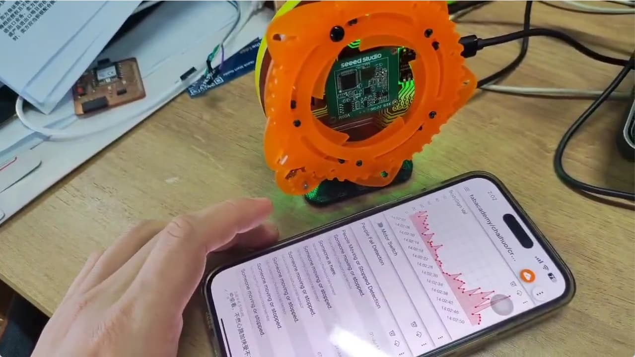
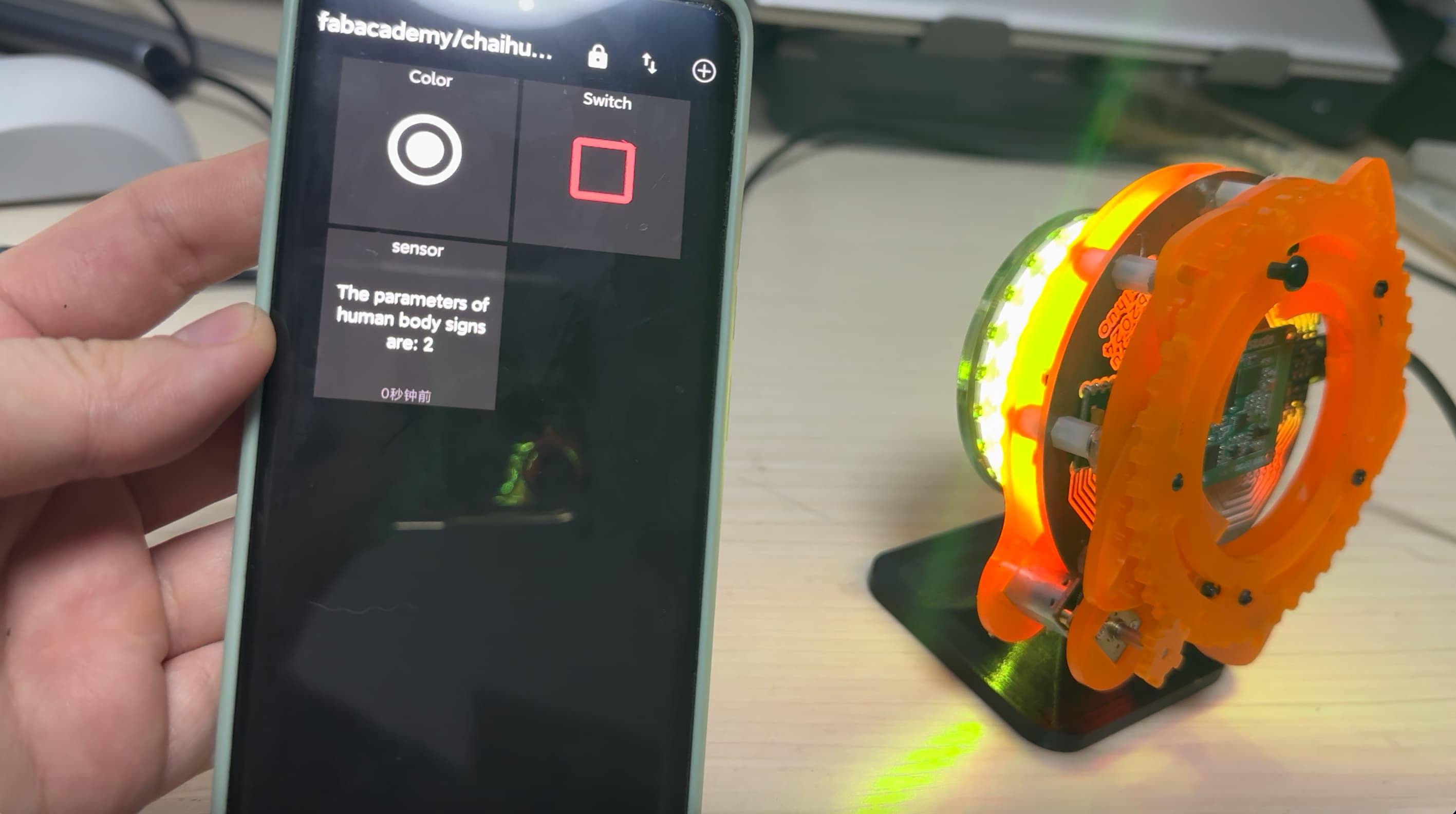
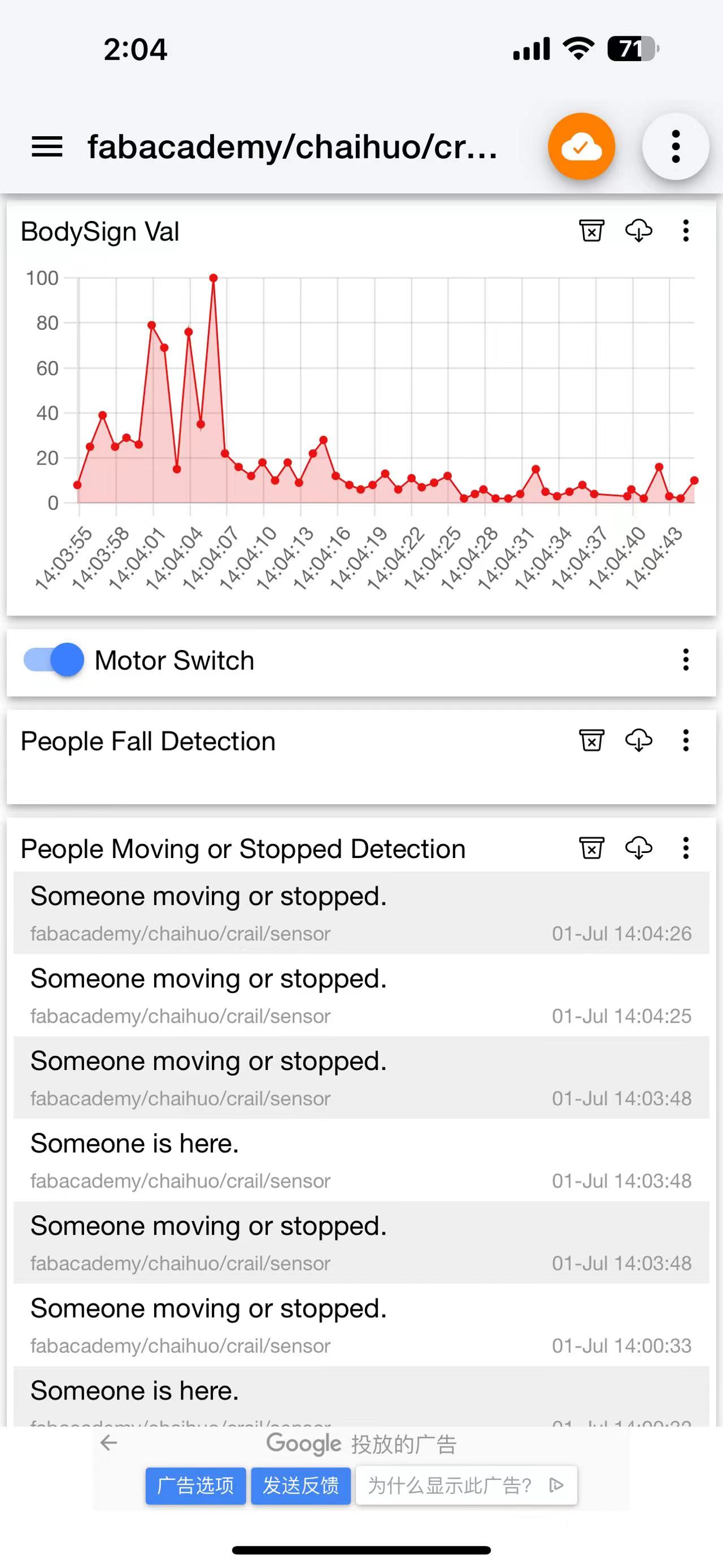
- Report real-time data to the mobile phone APP through MQTT for data display. Through the following screenshot, you can see that the data is being transmitted in real time, and the abnormal monitoring results are listed separately and reported.
After corrections, I successfully interfaced the boards and tested them with my laptop using the Serial monitor:
I use the LED to show the Sensor data if it tested someone is stopped in front of the devices.
Summary
This project taught me valuable lessons in meticulous design planning, the importance of simulation before manufacturing, and the resilience needed to troubleshoot and correct errors. Through mentorship and hands-on experience, I overcame challenges in PCB design and testing, ultimately achieving a functional circuit board for my project.
Source code and final showcase
Here is the source code for everything works.
#include <60ghzfalldetection.h>
#include <SoftwareSerial.h>
#include <WiFi.h>
#include <PubSubClient.h>
#include <Adafruit_NeoPixel.h>

// Define the pins for SoftwareSerial
#define RX_Pin A2
#define TX_Pin A3
#define LED_PIN 9

// Define the control inputs for a single motor
#define MOT_A1_PIN D0
#define MOT_A2_PIN D1

// MQTT Broker Details
const char* ssid = "x.factory";               // WiFi Name
const char* password = "make0314";    // WiFi Password
const char* mqtt_server = "mqtt.fabcloud.org"; // MQTT Broker Name
const char* mqtt_username = "fabacademy"; // MQTT Username
const char* mqtt_password = "fabacademy"; // MQTT Password
const char* mqtt_topic = "fabacademy/chaihuo/crail/sensor"; // MQTT Topic
const char* mqtt_topic1 = "fabacademy/chaihuo/crail/rawdata"; // MQTT Topic1
const char* mqtt_topic_fall = "fabacademy/chaihuo/crail/fall"; // MQTT Topic for Fall
const char* mqtt_topic_motor = "fabacademy/chaihuo/crail/motor"; // MQTT Topic for Motor Control

WiFiClient espClient;
PubSubClient client(espClient);

SoftwareSerial mySerial(RX_Pin, TX_Pin);
FallDetection_60GHz radar = FallDetection_60GHz(&mySerial);

Adafruit_NeoPixel strip = Adafruit_NeoPixel(24, LED_PIN, NEO_GRB + NEO_KHZ800);

bool motorSequenceExecuted = false;

void setup() {
  Serial.begin(115200);
  mySerial.begin(115200);
  setup_wifi();
  client.setServer(mqtt_server, 1883);
  client.setCallback(mqttCallback);
  client.subscribe(mqtt_topic_motor);

  strip.begin();
  strip.setBrightness(50);

  // Motor control setup
  pinMode(MOT_A1_PIN, OUTPUT);
  pinMode(MOT_A2_PIN, OUTPUT);

  // Turn off motor - Initial state
  digitalWrite(MOT_A1_PIN, LOW);
  digitalWrite(MOT_A2_PIN, LOW);
}

void loop() {
  if (!client.connected()) {
    reconnect();
  }
  client.loop();

  radar.HumanExis_Func();
  if (radar.sensor_report != 0x00) {
    handleRadarReport(radar.sensor_report);
  }
}

void mqttCallback(char* topic, byte* payload, unsigned int length) {
  String message;
  for (unsigned int i = 0; i < length; i++) {
    message += (char)payload[i];
  }
  Serial.print("Message arrived on topic: ");
  Serial.print(topic);
  Serial.print(". Message: ");
  Serial.println(message);

  if (String(topic) == mqtt_topic_motor) {
    if (message == "ON") {
      runMotorSequence();
    } else if (message == "OFF") {
      stopMotor();
    }
  }
}

void runMotorSequence() {
  Serial.println("Running motor sequence...");

  // Ramp speed up.
  for (int i = 0; i < 6; i++) {
    spin_and_wait(25 * i, 150);
  }

  // Ramp speed into full reverse.
  for (int i = 0; i < 6 ; i++) {
    spin_and_wait(135 - 25 * i, 150);
  }

  // Stop.
  spin_and_wait(0, 100);

  Serial.println("Motor sequence completed.");
}

void stopMotor() {
  Serial.println("Stopping motor...");

  for (int i = 0; i < 6; i++) {
    spin_and_wait(-25 * i, 150);
  }

  // Ramp speed into full reverse.
  for (int i = 0; i < 6 ; i++) {
    spin_and_wait(-135 + 25 * i, 150);
  }

  Serial.println("Motor stopped.");
}

void handleRadarReport(uint8_t report) {
  String message;
  String message1;
  uint32_t color;
  switch (report) {
    case NOONE:
      message = "Nobody here.";
      color = strip.Color(0, 0, 0); // Off
      publishMQTT(mqtt_topic, message);
      break;
    case SOMEONE:
      message = "Someone is here.";
      color = strip.Color(255, 255, 255); // White
      publishMQTT(mqtt_topic, message);
      break;
    case NONEPSE:
      message = "No human activity messages.";
      color = strip.Color(0, 0, 0); // Off
      publishMQTT(mqtt_topic, message);
      break;
    case STATION:
    case MOVE:
      message = "Someone moving or stopped.";
      color = strip.Color(255, 255, 0); // Yellow
      publishMQTT(mqtt_topic, message);
      break;
    case BODYVAL:
      message1 = String(radar.bodysign_val, DEC);
      color = strip.Color(0, 255, 0); // Green
      publishMQTT(mqtt_topic1, message1);
      break;
    case FALL:
      message = "Someone fell!";
      color = strip.Color(255, 0, 0); // Red
      publishMQTT(mqtt_topic, message);
      publishMQTT(mqtt_topic_fall, message);
      break;
  }

  Serial.println(message);
  if (report == BODYVAL) {
    Serial.println(message1);
  }
  setColor(color); // Set LED color
  delay(200); // Delay for 0.2 seconds to prevent rapid flashing
}

void publishMQTT(const char* topic, String message) {
  if (!client.connected()) {
    reconnect();
  }
  client.loop();

  if (client.connected()) {
    client.publish(topic, message.c_str());
  }
}

void setup_wifi() {
  delay(10);
  Serial.println();
  Serial.print("Connecting to ");
  Serial.println(ssid);

  WiFi.mode(WIFI_STA);
  WiFi.begin(ssid, password);

  while (WiFi.status() != WL_CONNECTED) {
    delay(500);
    Serial.print(".");
  }

  Serial.println("");
  Serial.println("WiFi connected");
  Serial.println("IP address: ");
  Serial.println(WiFi.localIP());
}

void reconnect() {
  while (!client.connected()) {
    Serial.print("Attempting MQTT connection...");
    String clientId = "XIAO-ESP32-Client-";
    clientId += String(random(0xffff), HEX);
    if (client.connect(clientId.c_str(), mqtt_username, mqtt_password)) {
      Serial.println("connected");
      client.subscribe(mqtt_topic_motor); // Subscribe to the motor control topic
    } else {
      Serial.print("failed, rc=");
      Serial.print(client.state());
      Serial.println(" try again in 5 seconds");
      delay(5000);
    }
  }
}

void setColor(uint32_t color) {
  for (uint16_t i = 0; i < strip.numPixels(); i++) {
    strip.setPixelColor(i, color);
  }
  strip.show();
}

/// Set the current on the motor using PWM and directional logic.
///
/// \param pwm    PWM duty cycle ranging from -255 full reverse to 255 full forward
/// \param IN1_PIN  pin number xIN1 for the given channel
/// \param IN2_PIN  pin number xIN2 for the given channel
void set_motor_pwm(int pwm, int IN1_PIN, int IN2_PIN) {
  if (pwm < 0) {  // reverse speeds
    analogWrite(IN1_PIN, -pwm);
    digitalWrite(IN2_PIN, LOW);
  } else { // stop or forward
    digitalWrite(IN1_PIN, LOW);
    analogWrite(IN2_PIN, pwm);
  }
}

/// Set the current on the motor.
///
/// \param pwm_A  motor A PWM, -255 to 255
void set_motor_current(int pwm_A) {
  set_motor_pwm(pwm_A, MOT_A1_PIN, MOT_A2_PIN);

  // Print a status message to the console.
  Serial.print("Set motor A PWM = ");
  Serial.println(pwm_A);
}

/// Simple primitive for the motion sequence to set a speed and wait for an interval.
///
/// \param pwm_A  motor A PWM, -255 to 255
/// \param duration delay in milliseconds
void spin_and_wait(int pwm_A, int duration) {
  set_motor_current(pwm_A);
  delay(duration);
}