18. Project Development
Final Projects!
Instead of working in plants I followed my new found interest in pottery and decided to make a pottery wheel. Alongside that I've also decided to continue pursuing making a handheld device gaming device. Both of these projects explore very different techniques and tools and so I thought it would be a good way to broaden my knowledge of the available equipment in the lab.
Dream Wheel
For the pottery wheel I took inspiration from many Youtube videos and experienced DIYers. A first version is documented in week 10. To summarize that week:
- An initial box/housing was made for the motor, shaft, electronics, and gears.
- A wheel head was cut out of acryllic
- Gears were printed out of acryllic with a 7:2 ratio.
- A 8mm threaded shaft was used for the main shaft.
- Used a washer/nut system to lock the shaft gear in place
- Had a simple breadboard setup for the electronics with potentiometer attached
We made great progress in machine week but it wasn't actually functional for several reasons and there were a lot of stability concerns. Things I wanted to improve were
- A better gear ratio for more torque. The motor I was using provided 250 watts of power, which was at the lower end of the power requirement for a pottery wheel. Luckily at ~2500 rpm we had plenty of room for a gear reduction while also maintaining ample speed.
- A thicker, more stable shaft. This will make it stay straight even with several forces acting on it.
- A better match between shaft and bearings. The amount of wobble our initial wheel had was caused a lot by the amount of wiggle room the shaft had within the bearings.
- A more stable housing for the bearings. Also makes it easier to replace and remove.
- A better way to fix the gear to the motor. The motor shaft was short and of variable thicknesses throughout. The gears were also getting worn down over time.
- Actually cutting the top plates so clay could be thrown on top of the wheel
- A splashpan to collect water from the clay shaping process
- Waterproofing the electronics and motor
- Making a PCB for the project vs using a breadboard
In week 16 I document how some of these issues would be addressed. Particularly the
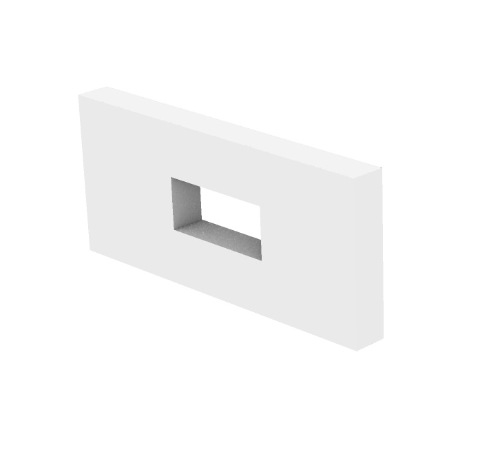
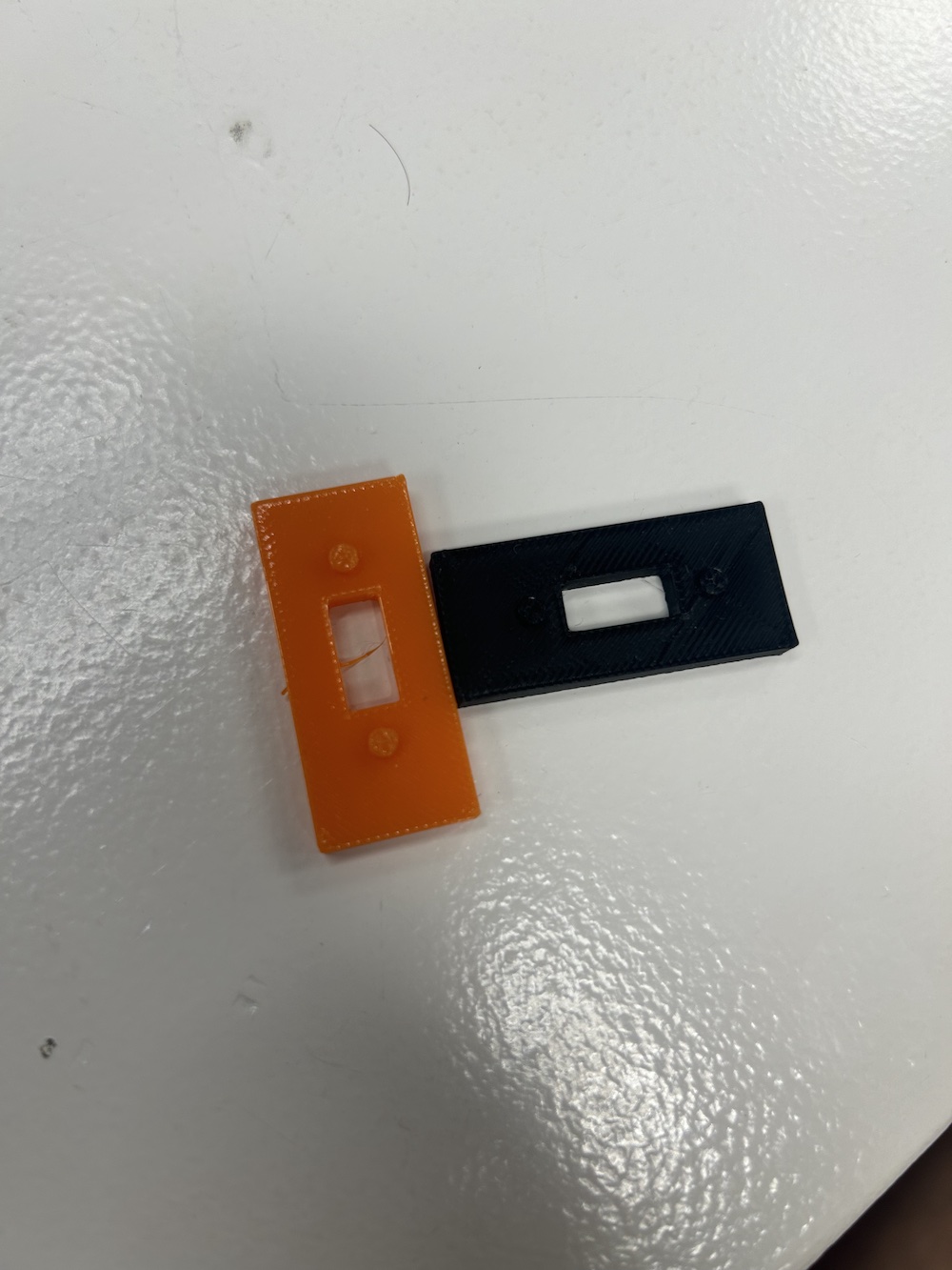
- The motor sleeve (for better gear fit on motor shaft)
Failure graveyard (it was much bigger than this) 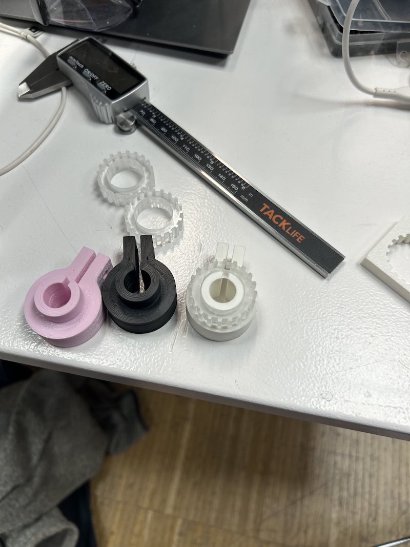
Motor sleeve fitting snug 
Gears glued onto sleeve 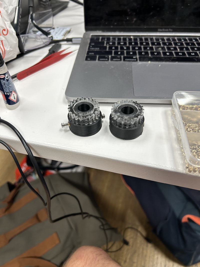
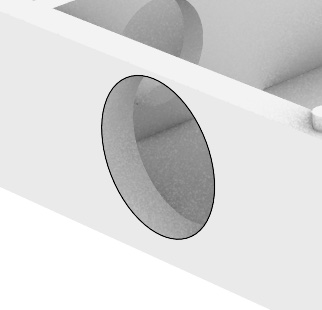
- A bearing housing for main shaft bearings
Bearing housings 
- A simple splashpan design.
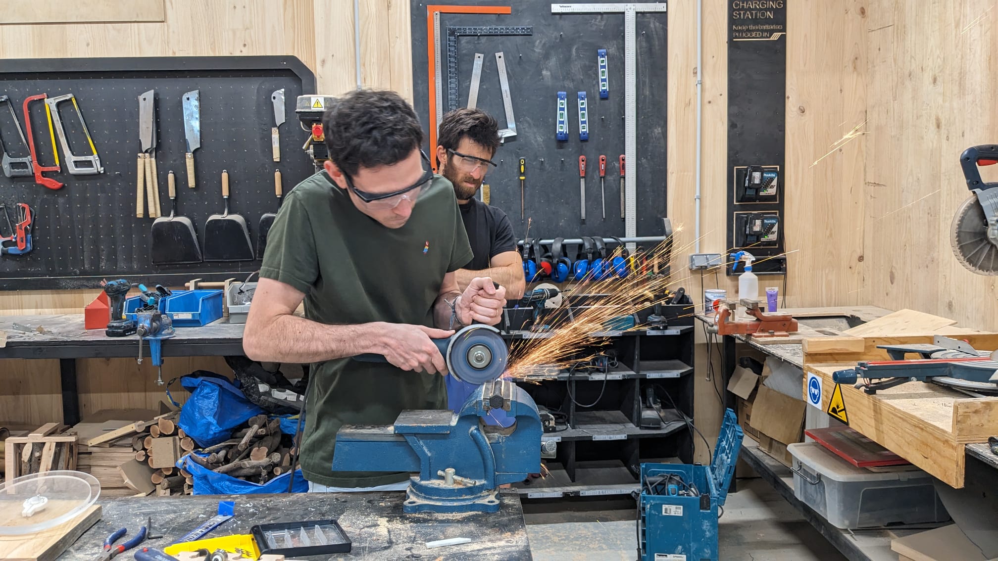
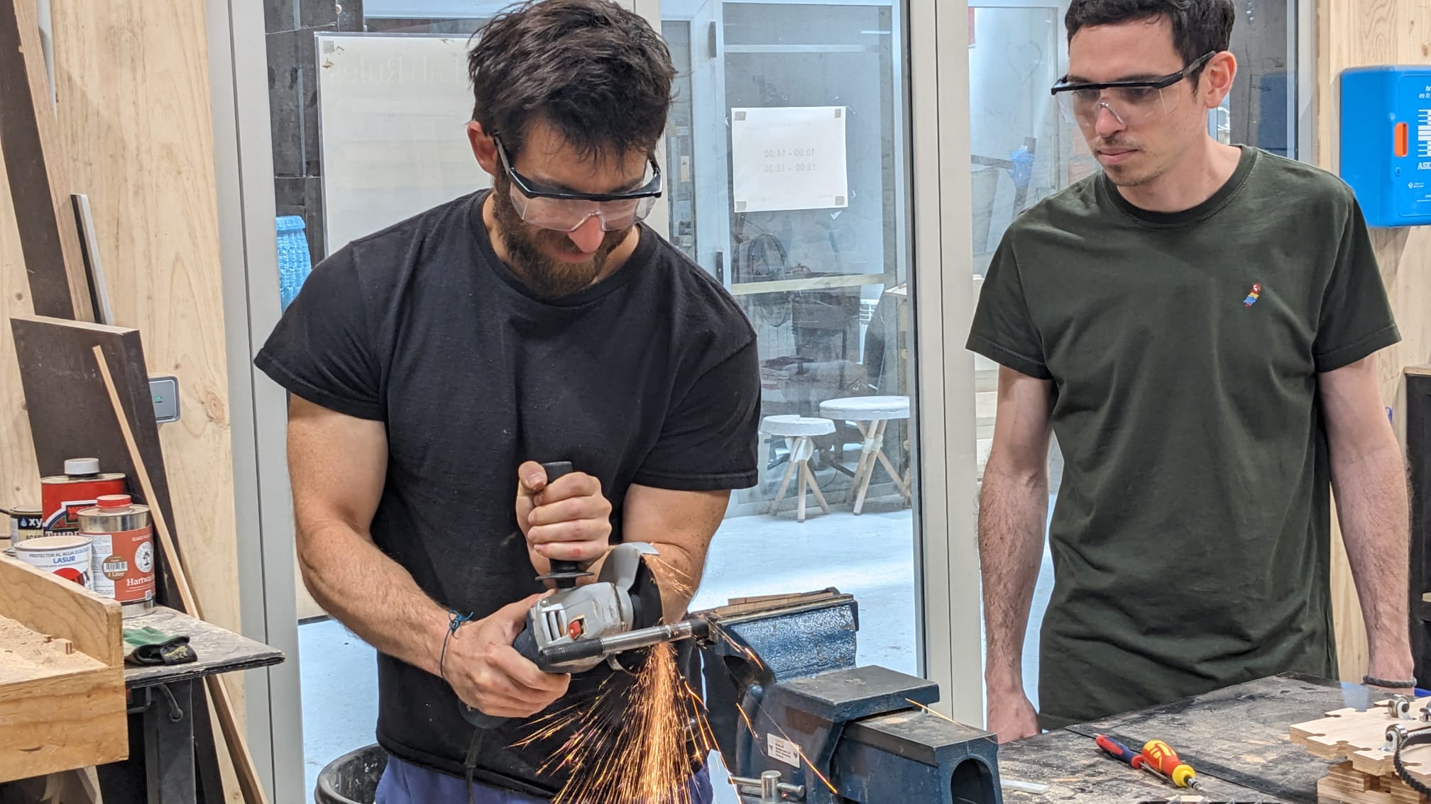
I ended up buying a 16 mm large screw to address the strength of the shaft. This was also chosen because 16mm bearings were the most readily available for me to get delivered. I would've preferred a calibrated rod for the shaft but even still, it was a big upgrade. My classmate and friend, Riichi and I cut the shaft down to a size and ended up adding some more threading (no pictures of that, sadly) so fix the bottom of it to the inner ring of the bearing with a nut for more stability.
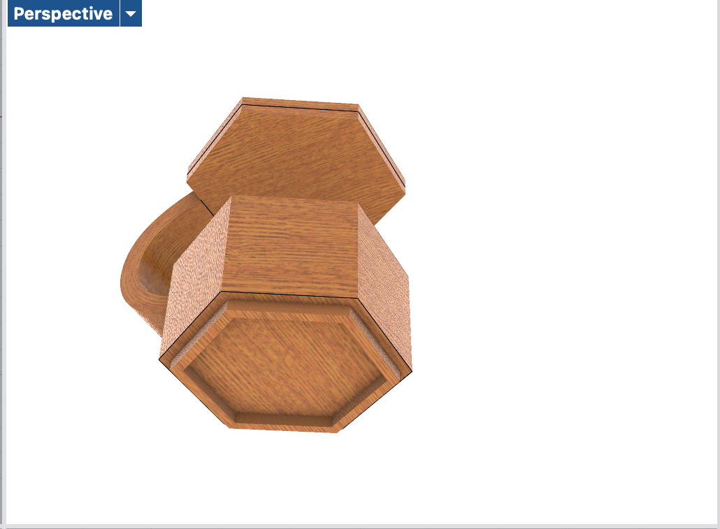
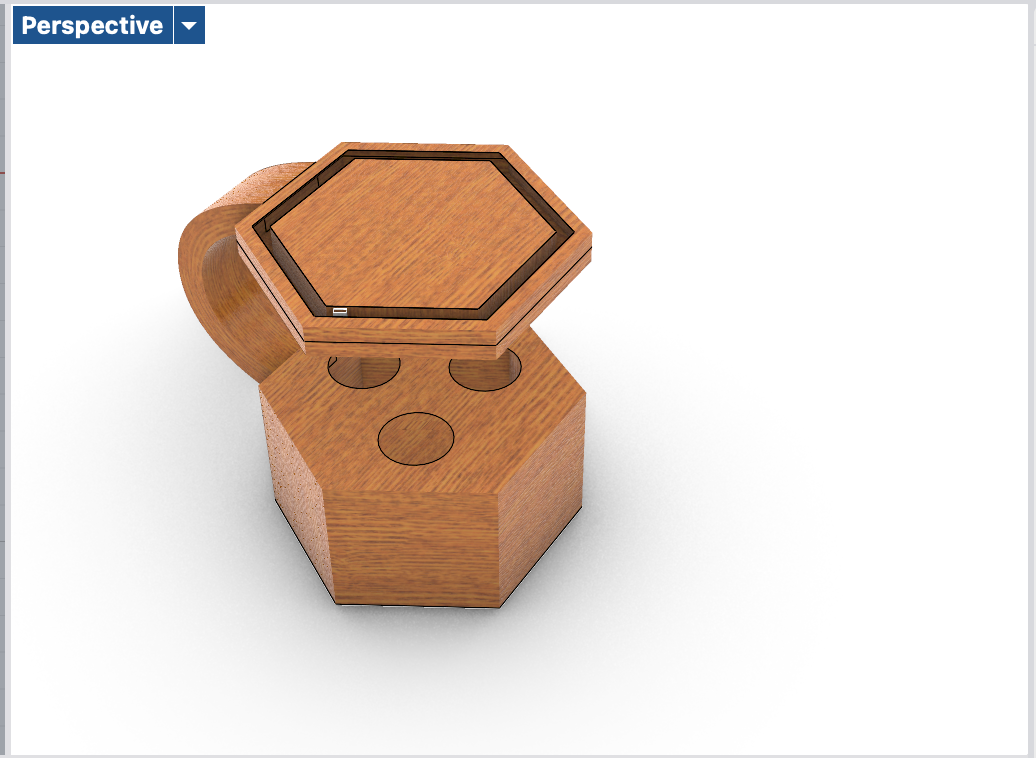
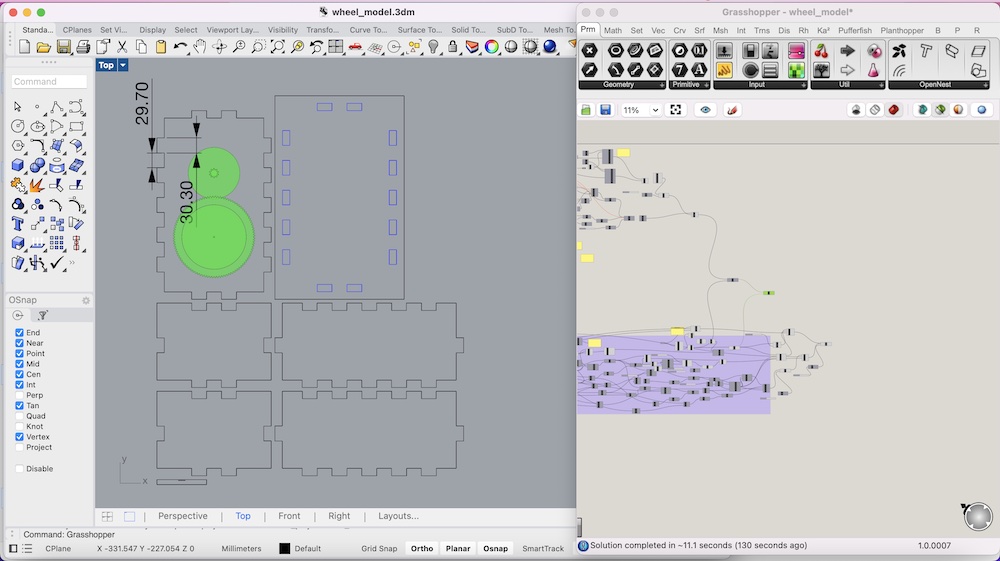
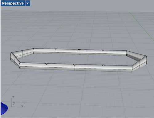
I also used my wheel model in grasshopper to ensure the box would be a reasonable size and would automatically dogbone the corners of the box for a better fit when snapping the edges together.
I calculated for a gear ratio of 10:1 with some tolerance just in case another gear ratio was used.
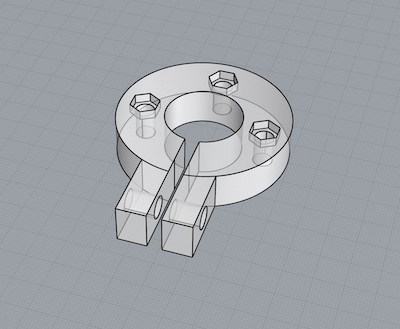
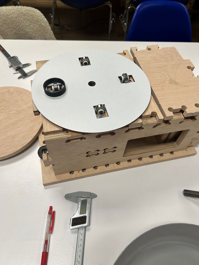
Later I CNCed the box but without part of the top, front, and back as those weren't necessarily needed for testing. Riichi and I assembled everything but because I was no longer using a threaded rod (apart from the bottom anyway), no nuts could be used to lock the shaft's gear in place. I ended up making a variation of the motor sleeve with screw placements for the gear plates.
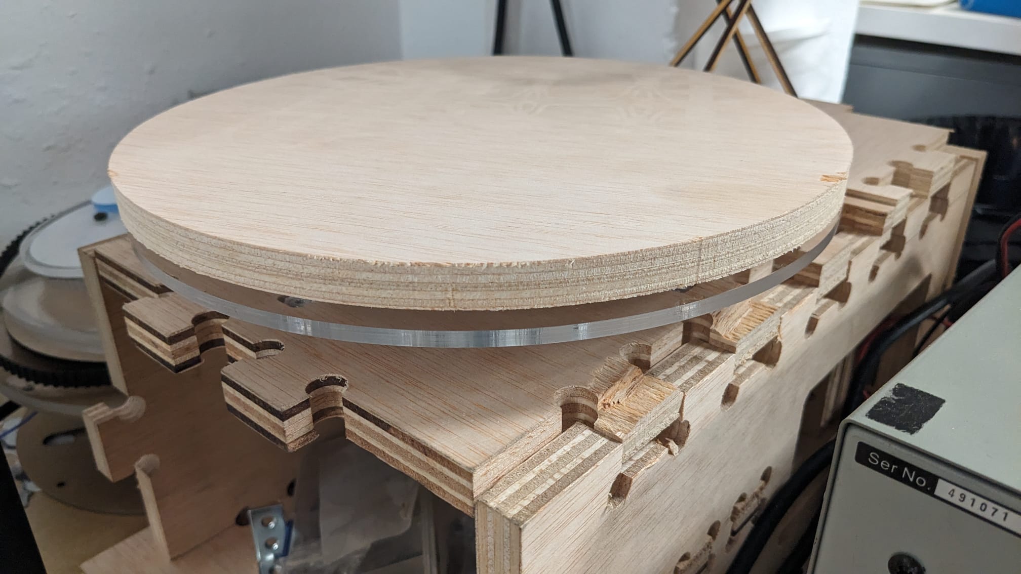
The first test looked great! There was minimal friction and it looked very straight. Riichi also found a great way to secure the wheel plate to the top part of the screw with a hugger below the plate, squeezing the top part of the plate into the the bottom part of the hexagonal end of the shaft. We then had to stack a few more plates to avoid the hexagonal portion going through the top piece of plywood (the bat), where clay would actually be thrown.
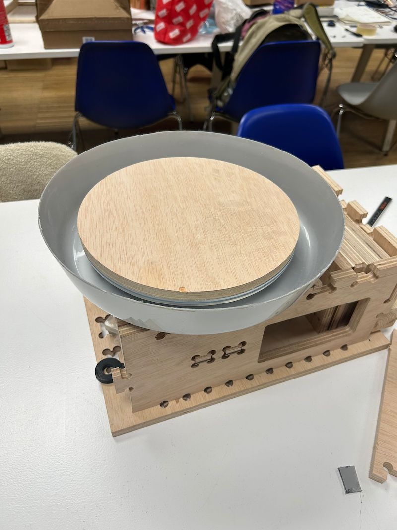
Once that gap was filled it seemed everything was actually in order! But we still needed a splash pan to collect water. This is important because it's the first layer of protection against water damage for the wheel (which should not be relied on in reality) and more commonly, to avoid huge messes while working with clay. Originally I was going to 3D print a splash pan but one of our instructors, Josep, had a great suggestion- he said to just go buy a palangana which is just a basin used to collect water. Riichi and I walked over and bought one at a local bazar. We then cut off the top because it was prohibitively tall. We did this with a dremel. Julia, our instructor, had a great suggestion on how to ensure the wall would stay even while cutting around.
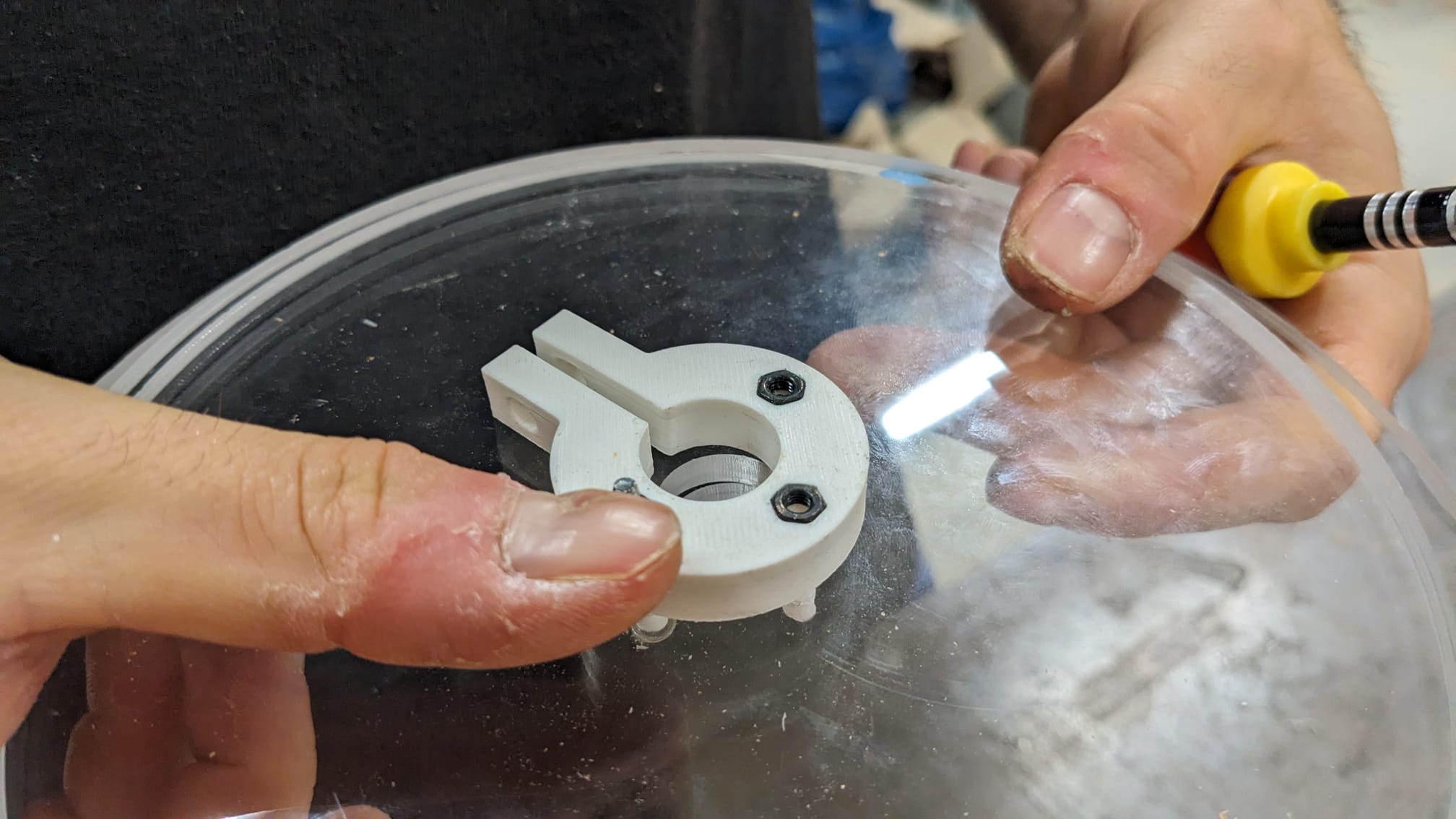
We also had to cut holes around where the bearings would be so the pan could fit around them but under the working wheel. This was a bit tricky because we also didn't want water to get into the bearings. I ended up printing some simple cylinders with the idea that they could be attached with silicon to the splash pan and surround the bearings, putting a barrier between the bearings and the water flowing in from the outside. I also laser cut a template in cardboard to ensure I'd get the positions exactly correct when cutting out the holes in the splash pan.
That step may have been the only one that actually went exactly to plan.
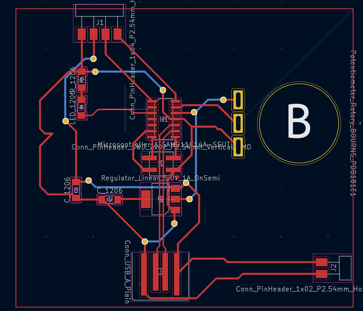
Finally I CNCed the remaining panels to close the box and began work on the PCB. For the PCB I chose a SAMD11. Riichi also let me use his potentiometer footprint as he had worked with them quite a bit throughout his project and there was not any available in our fab kicad library originally. Another classmate, Magdalena, also let me look at her SAMD11 PCB files (who got help from Max) and that was super helpful to work quickly as well (thank you both).
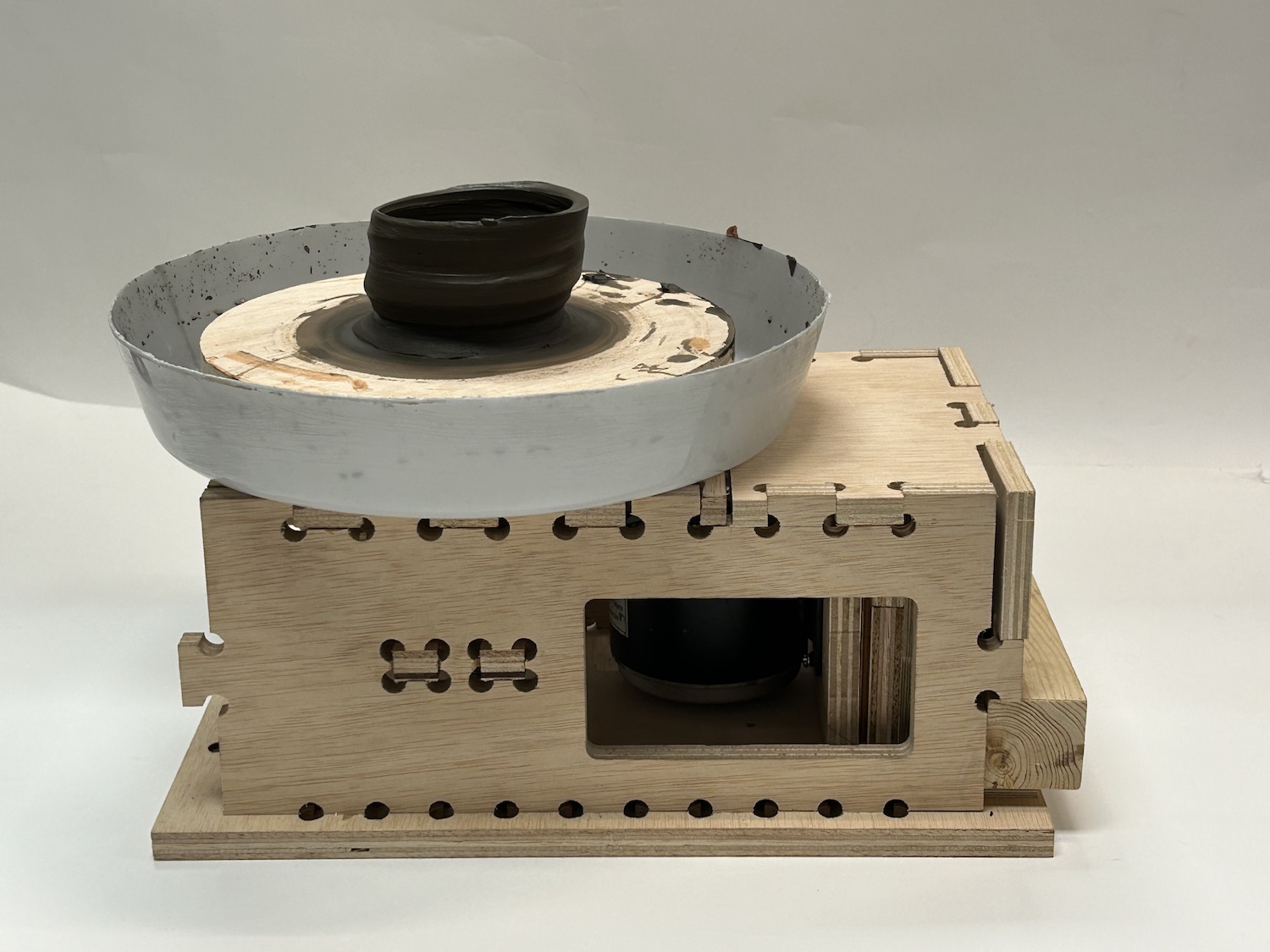
I added the final panels, closed up the box and hooked up the electronics with the H-Bridge to control the voltage output to the motor. This gives it variable speed and direction. Finally I threw some clay on that sucker.
Thank you to the instructors- Josep, Girard, Julia, and Adai for helping out with this. Several classmates also gave great pointers along the way. And a special, big thanks to Riichi who was basically my partner for the last couple of weeks on the project. I couldn't have done it without him.
Pug Boy
In week 8 I had designed a PCB and a simple pong game for it. This sprouted the idea of making an actual gaming device. In networking week I also added peer to peer multiplayer which allows people to play with each other up to 400 meters (allegedly) apart. I had also made a reinforcement learned AI in a previous week for the pong opponent as documented in wildcard week. A lot of great funcitonality had already been implemented. There were many ideas that I wanted to execute on at some point down the line but time is time. Many of these can be read about in week 16. To call this a complete project I knew I had to make a nice casing and add a super snazzy logo to it. I also wanted to make it battery powered.
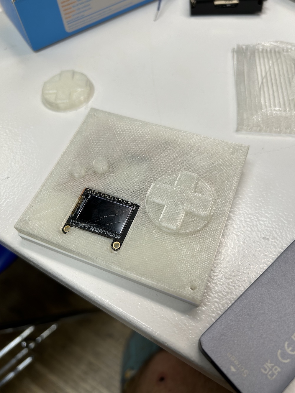
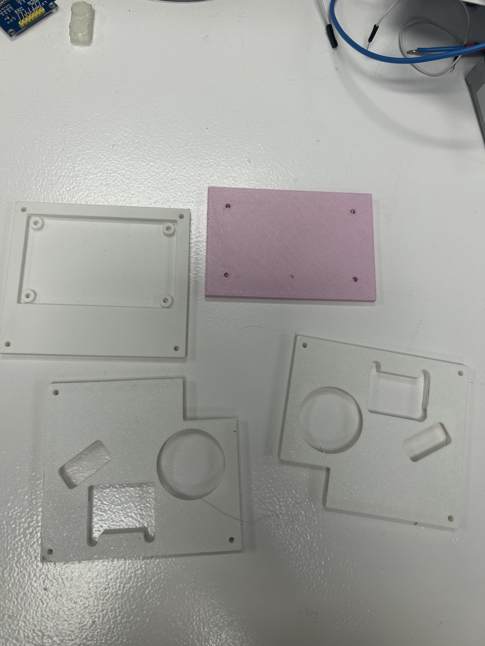
The first thing I did was print a simple back casing where I tested if the board could just stay snuggly by press fitting. This was Danni's suggestion (gracias, tronco). It worked perfectly. I also added little screw placements to the design but in the end never ended up using them.
Now that I had a solid fit for the board I started thinking about the cover and the buttons.
I did an initial 3D print with PLA for the cover and TPU, a more rubbery material for the buttons. The TPU did work well but it was a little clunky. I was close and tempted to just finish the project as it was but another classmate with a bit more design sense, Susanna, insisted I could do better! Her suggestion was to print the entire cover in one piece, all as the rubbery substance, TPU. I grudgingly accepted the extra work. I have to say listening to the advice may have been the best decision I made for the project. The result was great and the buttons worked much better. Thank you ma'aam.
Finally I had to worry about the back case that would hold the battery and the on/off switch. Although a simple design I did manage to screw that up several times.
As I was also using different switches (we only had 1 switch in stock for one of the switch types) for the 2 controllers--I wanted multiplayer to be used within the packaging--I ended up printing some quick tests to avoid printing everything and having it fail beacuse of tolerances.
For the battery, rather than recut my board to more properly acommodate it, I soldered the switch output and ground from the battery directly to the inputs of my boards voltage regulator. This was a bit hacky but very fast and effective. I used snapping for the back cover for the battery portion of the casing. It was more or less functional. I also tried to do the same with the all TPU cover, rather than using screws. Unfortunately the texture of the TPU didn't work well and i had to use double sided tape to ensure the cover stayed on snuggly.
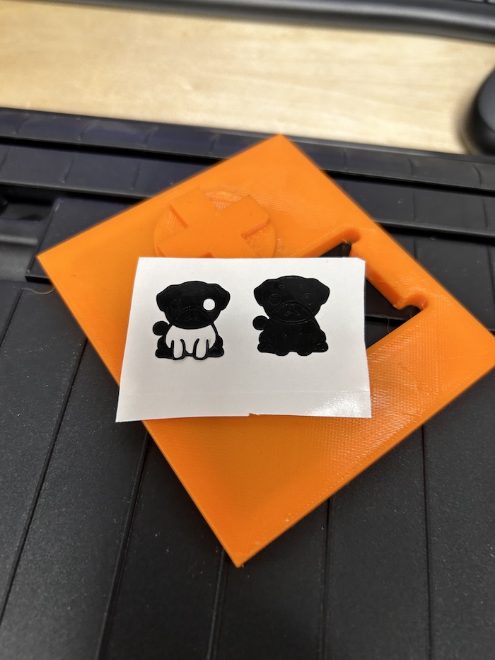
Finally the branding...I did a vinyl cut of a pug I had chatgpt draw and used inkscape to prepare it. In the end the design was too intricate for my hands to actually get correct when peeling but it still looked damned good.
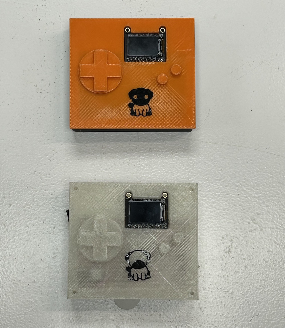
After printing my first case, I made the second case thinner and filleted the edges as well for a better look/feel. Here they are together in all their glory.
My final presentation video and slide can be found here and here. Thanks for reading, it's been great.
Final Project Addendum
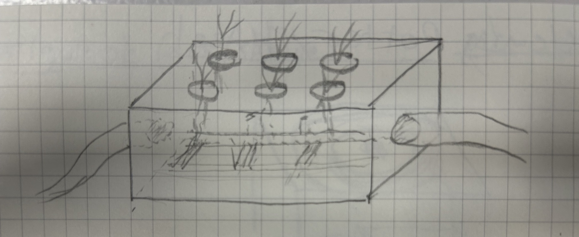
This was my idea at the beginning of fablab
For my final project I would like to make a garden that can be mostly self-monitored.
The main priorities for this project are
- To optimize a small amount of space efficiently.
- Easy to get started and maintain
- Indoor
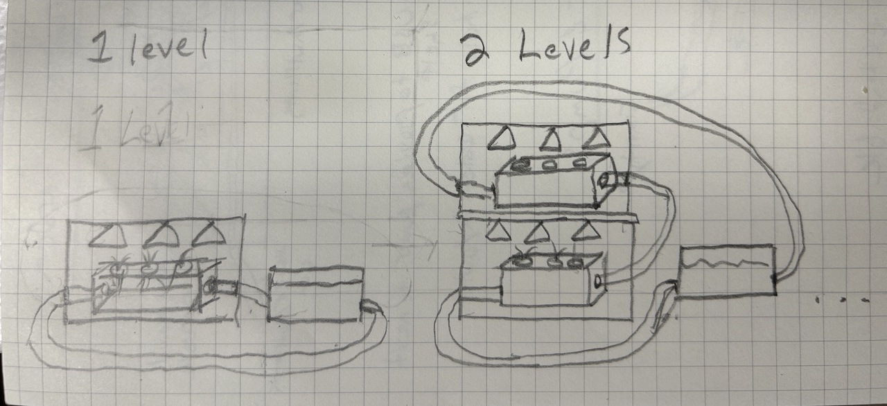
- Expandable- You can have 1 level of plants or you can add multiple levels without much extra effort
- Easily Extensible- if in the future another contributor would like to add additional features, this should be easy
- Inexpensive
- Material wise, keep the cost down to make it
- In terms of energy, find ways to use less or have green sources (solar?)
- Vertical- the garden can be built upward, minimizing surface area. This has become a popular method in more urban areas over the past few years.
- Stackable shelves- allows a gardener to start with a small plot and slowly expand upward without using more room than necessary
- Automated/minimal human intervention- Pumps on a timer for watering and delivering nutrients to the plants
- Aeroponics- A method of growing plants where their roots hang in the air and get sprayed with a mix of water and plant food. It's different from the usual way of growing plants in soil because it lets you carefully control how much nutrients the plants get. This can make plants grow faster and produce more yield than traditional methods. Also, without soil, there are fewer problems with bugs and diseases.
Overview

Plant Container
Adding Layers
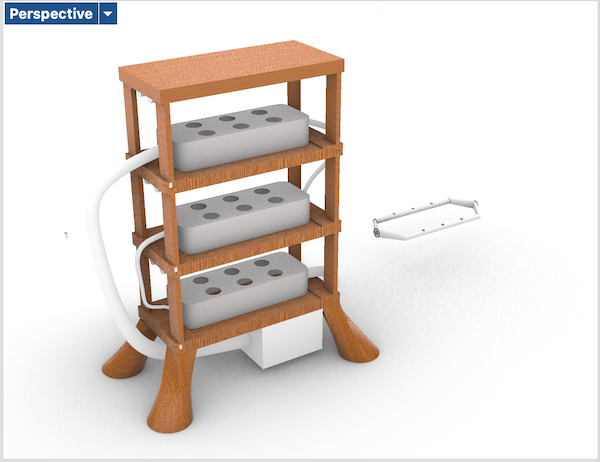
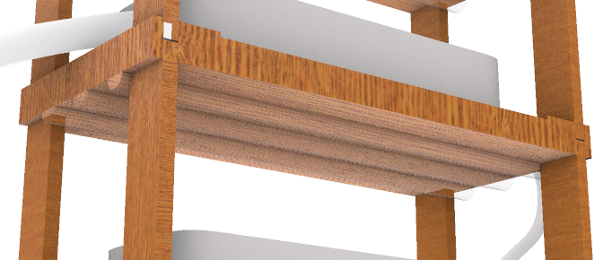
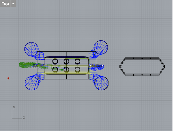
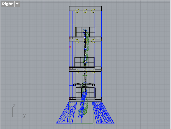
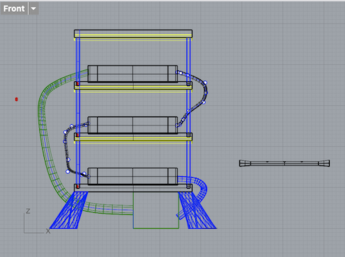
V1 of 3D models with Rhino
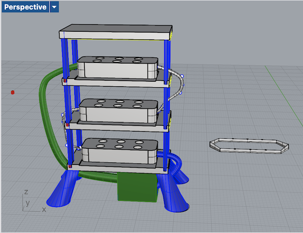
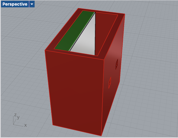
Alternative Model- No Separate Shelving