16. Applications and Implications
This week's assignment is to elaborate and flesh out details of our final project from the processes and components it will use and their associated costs to prior work on similar types of projects and what our project adds (if anything) or how it differs.
I've decided to do 2 final projects because they are two fields I had wanted to explore for different reasons and I couldn't decide on just one. In no particular order...
Project 1: Pottery Wheel
What will it do?
Recently I've taken a dive into pottery and have been inspired to build my own for a relatively cheap price while also making it a very repeatable process. At a bare minimum the pottery wheel should:
- Have the ability to spin in either direction (clockwise and counter-clockwise)
- change speeds with foot pedal
- Water proof- because water is a big part of the ceramics process I will need to make sure all of the electronics involved aren't vulnerable to water damage
- High torque- because of the force/weight of the clay and the person pressing onto the wheel, the wheel needs to spin with enough torque to not slow down appreciably while working with some reasonable amount of clay
- Spins with minimum wobble- the less wobble and more flat the wheel head can stay, the easier it is to make pieces.
Who's done what before?
Many many people have made a pottery wheel before. My first version isn't really about uniqueness but more for personal use and something I can build on and add interesting features in the future.
What will you design?
For this project I will be designing a few different components using Rhino/Grasshopper.
- The structure/housing for the motor, gears, shaft. This also includes calculating the appropriate dimensions of the container based on gear ratios and the length of the gear band.
- The housings for the bearings, which are 3D printed. This allows for the bearings to be fixed to the box structure
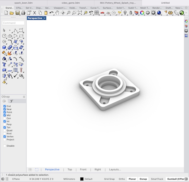
- The Splash pan- This is used to collect the waste while shaping the piece. This comes in the form of excess clay and water. It will need to be removable for cleaning and is generally broken into two parts. Each side is slid underneath the wheel and attach to each other through one of various mechanisms. Because of the size and shape of this will likely be 3D printed in parts and then assembled after or of possibly theramformed.
Half of splash pan 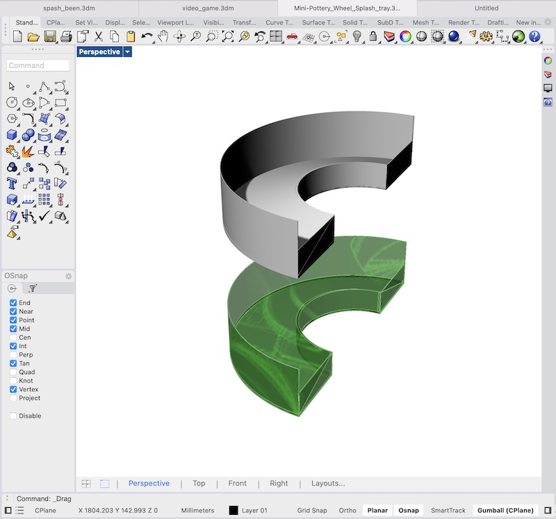
- Motor collar- This is 3D printed to sit around the motor's shaft and allows for a better based for which the its gears can fit on.
Motor collar with screw to tighten 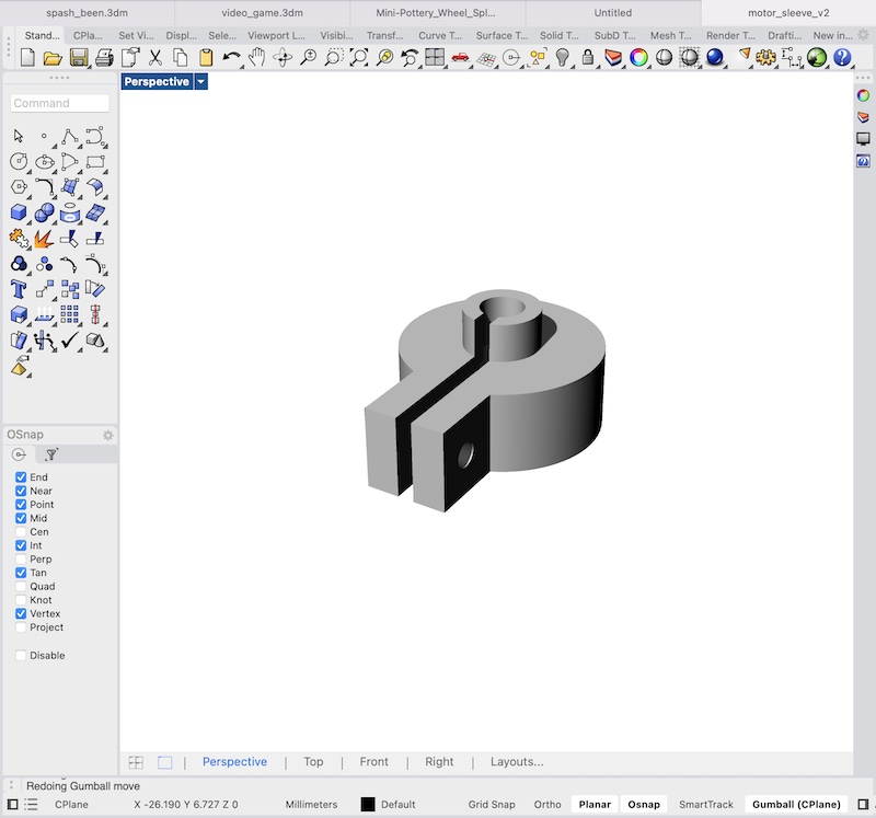
- The Bats- the actual working surface. These should be interchangable and removable. They can be made of plywood and either CNCed or laser cut depending on thickness.
- The wheelhead- This gives the base and stability for the bats
- Gears- There will 2 gears to get the torque appropriate for a pottery wheel. The motor spins at about 2500 RPM with a 24 volt power supply. It generates a maximum power of 250 watts which is near the bottom end of acceptable so it is important that the system is efficient. One gear will sit on the motor shaft and the other will be fixed to the shaft which will actually spin the wheel where the clay will be shaped on. Given a reasonable maximum speed of 250 rpm, a gear ratio of 10 to 1 gets the torque and speed we'd like. Some more speed could even be sacrified for torque if need be as very high speeds are not really as important as a consistent spin. The gear teeth have been modeled to match the band I'm using. These will be cut from acryllic and stacked to match the height of the band.
Gear Example 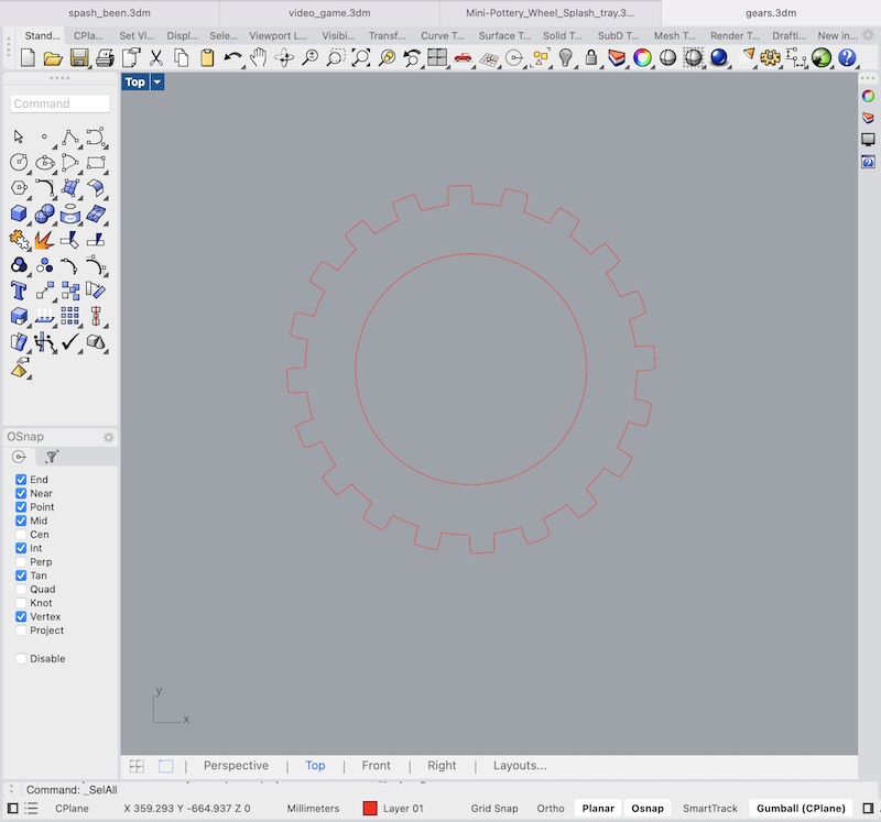
- The system to fix the larger gear to the wheel head (main) shaft. If using a threaded shaft this can be a nut sandwich. If it is a smooth surface I may buy metal couplers or 3D print my own.
- The speed/direction control system for the wheel- Because the wheel will need to change speeds (depending on where in the shaping process the user is) and direction (depending on the on the handedness of the person) some electronics will need to be used to control these things. A simple PCB can be milled to connect to an H Bridge (which is used to control ouput voltage). a small microcontroller can be used to increase/decrease voltage through PWM to the motor through a potentiometer input.
- Foot pedal (?) integrated with potentiometer to control speed. All standard pottery wheels have a foot pedal. An old guitar foot pedal may suffice.
What materials and components will be used?
- 15 mm plywood (for the main housing/box) and the bats. Prices for a 1440mm x 1220mm piece of plywood cost around 30-50 euros. The box will use around 1/10th of that. This would be 3-5 euros in material. You'll need a bit more than 260000 mm^2 of material.
- Copper PCB electronics board to control wheel. Something like this should serve. It will cost 2-3 euros.
- 250 Watt motor- Ideally you can find a spare one from another machine but the one I used is around 17 euros
- 5 mm Acryllic for gears and wheelhead (tentatively). You can get them on amazon for 11-12 euros. This is also overkill for the amount needed. The cost of material is probably 1/10th or 1/5th o that. ~3-5 euros to be safe.
- 16 mm shaft bought locally for ~10 euros
- Bearings- either 16/18 mm inner diameter to match shaft (need to purchase) OR 17 mm inner diameter bearings (already purchased) that fit snugly with nuts and minimize wobble. About 0.50 euros per bearing (need 2)
- PLA for 3D prints. a few cents of material
- Palangana for the splash pan. Bought locally for 4 euros.
- Small microcontroller- either AtTiny or the SamD11. Samd11s seem to go for around 1-2 euros
- board components
- 2x 1uF capacitor
- 1x red led- sanity check
- 1x ~250 ohm resistor (can vary a bit)
- Potentiometer to control speed thru microcontroller. Approximately 1-2 euros
- 1x 4-pin female header (can also be male) to send signals to H-Bridge, 5v output, and ground
- 1x 2-pin female/male header to supply power (not necessarily required)
- H Bridge to manage voltage output to motor. Approximately 3-5 euros
- Band with teeth. 1-3 euros
What processes will be used?
- Laser cutting
- 3D printing
- CNC
- PCB milling
What questions need to be answered?
Main open questions are still if I can get a well-fitted bearing/shaft combination in time or if I will go with the current threaded solution. Second open question is if I can find a foot pedal solution. And secondarily I will need to see if printing the splash pan in parts will work and what the attachment mechanism will be for connecting the two halves.
Project 2: Portable Game Console
My other project stems from some work in week 8, week 13, and week 14 and I figured I'd continue it.
What will it do?
V0 should include:
- Single player
- Wireless peer to peer multiplayer. This builds on week 13, networking.
- Battery powered
- A somewhat aesthetically pleasing case with nice buttons. Ideally similar to Game Boy Pocket's
- AI using trained neural nets for at least one game (done is week 14)
- Depending on screen may be black and white
- Challenger lobby
V1 should include
- Multiple games
- Color
- Improved codebase to allow for 3rd party game making. Code is currently disgusting.
- Music generation in collaboration with Max
V2+ could include
- Use of gyroscope and accelerometer as extra control
- Ability for developers to add other peripherals.
- Allow users to build their own AIs through analog electronics.
- Possibility to import sprites store on local storage
Who's done what beforehand?
Everything I'd like to do has been done before until V2+ where there may be something new with the analog AI feature and allowing additional peripherals.
What will you design?
- The PCB/controller layout- This will dictate the final console as I plan to keep everything directly connected to the board, at least for v0.
Current PCB Layout 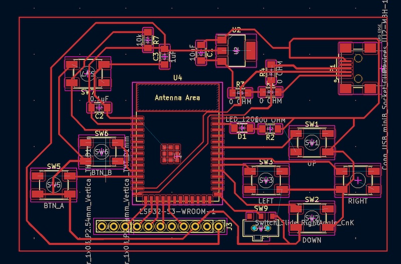
- The console case and buttons. As said previously, I really like the Game Boy Pocket aesthetic.
Case prototype (not looking like Game Boy Pocket...yet) 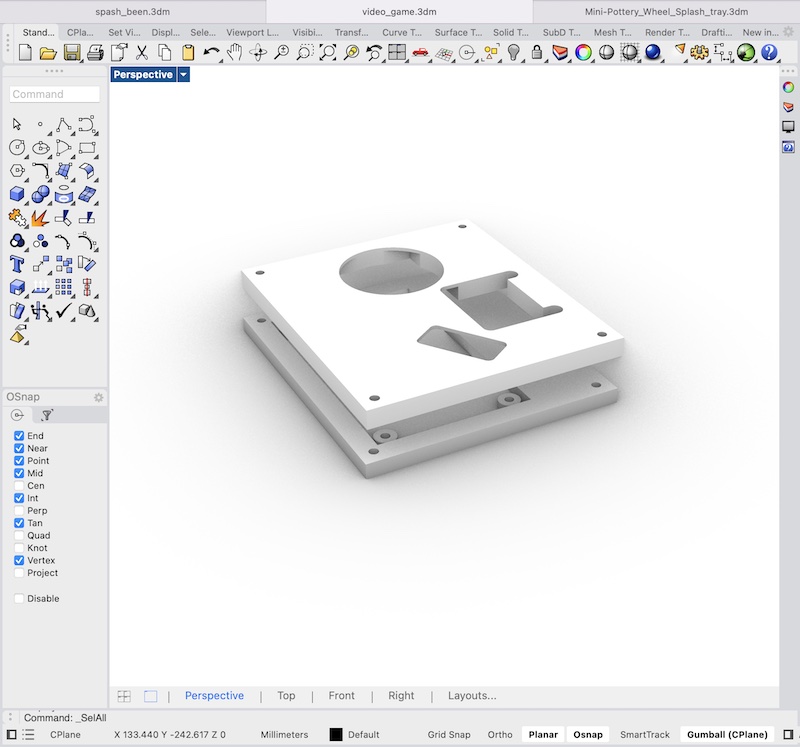
- Buttons- I need nice n comfy buttons for the player to use. Along with a D-pad.
What materials and components will be used?
- PLA- for 3D printed case. a few cents
- likely silicon for buttons. A few cents
- Switch for on/off with battery
- copper for PCB. 1-2 euros (see above for reference)
- ESP-32 S3 microcontroller. 4-5 euros
- board components- capacitors and resistors. minimal. < 1 euro.
- 3 capacitors- 0.1 microfarad, 1 microfarad, 10 microfarads
- 3 0 Ohm resistors (can be made double-sided to avoid)
- 1 10k Ohm resistor
- 6 push buttons- 4 for D-pad, 2 for A and B buttons, 1 for microcontroller reset
- 1 switch for putting board in boot mode
- Red diode led for sanity check
- LCD screen 1-5 euros.
What processes will be used?
- PCB milling
- 3D printing
- Mold and casting(?)
What questions need to be answered?
Open questions are if I can get a bigger and better screen with more data lines in time to for the deadline. This may also dictate whether or not the game is in color or not. Another open question is I have time to program a second game before the deadline.