Real Final Projects!
Dream Wheel
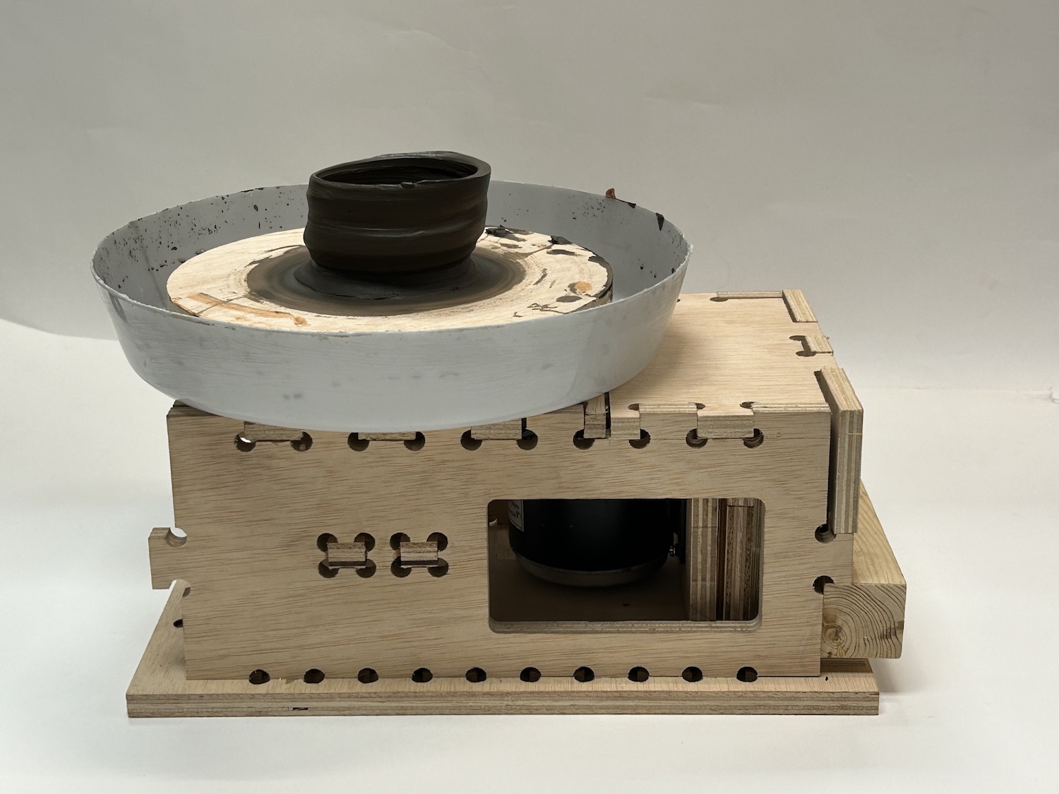
- The structure/housing for the motor, gears, shaft. This also includes calculating the appropriate dimensions of the container based on gear ratios and the length of the gear band. TODO: add pictures
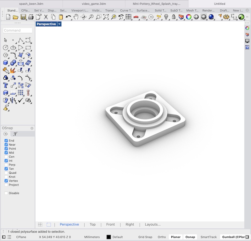
- The housings for the bearings, which are 3D printed. This allows for the bearings to be fixed to the box structure
- The Splash pan- This is used to collect the waste while shaping the piece. This comes in the form of excess clay and water. It will need to be removable for cleaning and is generally broken into two parts. Each side is slid underneath the wheel and attach to each other through one of various mechanisms. Because of the size and shape of this will likely be 3D printed in parts and then assembled after or of possibly theramformed.
Half of splash pan 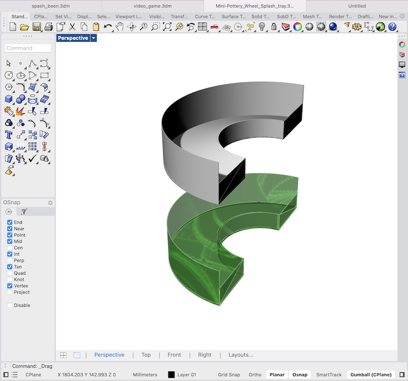
- Motor collar- This is 3D printed to sit around the motor's shaft and allows for a better based for which the its gears can fit on.
Motor collar with screw to tighten 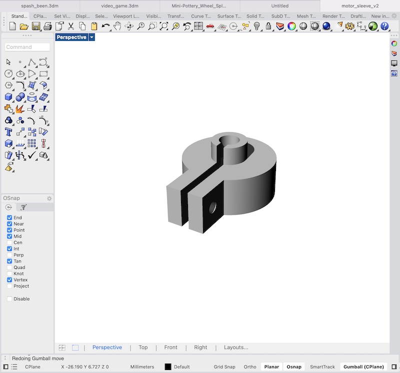
- The Bats- the actual working surface. These should be interchangable and removable. They can be made of plywood and either CNCed or laser cut depending on thickness.
- The wheelhead- This gives the base and stability for the bats- TODO: add pictures
- Gears- There will 2 gears to get the torque appropriate for a pottery wheel. The motor spins at about 2500 RPM with a 24 volt power supply. It generates a maximum power of 250 watts which is near the bottom end of acceptable so it is important that the system is efficient. One gear will sit on the motor shaft and the other will be fixed to the shaft which will actually spin the wheel where the clay will be shaped on. Given a reasonable maximum speed of 250 rpm, a gear ratio of 10 to 1 gets the torque and speed we'd like. Some more speed could even be sacrified for torque if need be as very high speeds are not really as important as a consistent spin. The gear teeth have been modeled to match the band I'm using. These will be cut from acryllic and stacked to match the height of the band.
Gear Example 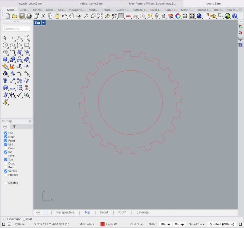
- The system to fix the larger gear to the wheel head (main) shaft. If using a threaded shaft this can be a nut sandwich. If it is a smooth surface I may buy metal couplers (TODO: show photos of these) or 3D print my own.
- The speed/direction control system for the wheel- Because the wheel will need to change speeds (depending on where in the shaping process the user is) and direction (depending on the on the handedness of the person) some electronics will need to be used to control these things. A simple PCB can be milled to connect to an H Bridge (which is used to control ouput voltage). a small microcontroller can be used to increase/decrease voltage through PWM to the motor through a potentiometer input.
-
PCB Design 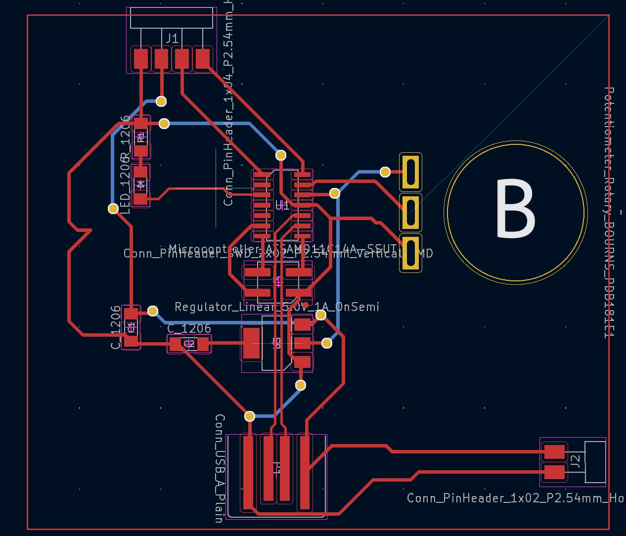
- 15 mm plywood (for the main housing/box) and the bats. Prices for a 1440mm x 1220mm piece of plywood cost around 30-50 euros. The box will use around 1/10th of that. This would be 3-5 euros in material. You'll need a bit more than 260000 mm^2 of material.
- Copper PCB electronics board to control wheel. Something like this should serve. It will cost 2-3 euros.
- 250 Watt motor- Ideally you can find a spare one from another machine but the one I used is around 17 euros
- 5 mm Acryllic for gears and wheelhead (tentatively). You can get them on amazon for 11-12 euros. This is also overkill for the amount needed. The cost of material is probably 1/10th or 1/5th o that. ~3-5 euros to be safe.
- 16 mm shaft bought locally for ~10 euros
- Bearings- either 16/18 mm inner diameter to match shaft (need to purchase) OR 17 mm inner diameter bearings (already purchased) that fit snugly with nuts and minimize wobble. About 0.50 euros per bearing (need 2)
- PLA for 3D prints. a few cents of material
- Palangana for the splash pan. Bought locally for 4 euros.
- Small microcontroller- either AtTiny or the SamD11. Samd11s seem to go for around 1-2 euros
- board components
- 2x 1uF capacitor
- 1x red led- sanity check
- 1x ~250 ohm resistor (can vary a bit)
- Potentiometer to control speed thru microcontroller. Approximately 1-2 euros
- 1x 4-pin female header (can also be male) to send signals to H-Bridge, 5v output, and ground
- 1x 2-pin female/male header to supply power (not necessarily required)
- H Bridge to manage voltage output to motor. Approximately 3-5 euros
- Band with teeth. 1-3 euros
- motor/shaft sleeve grasshopper file
- wheel plate rhino file
- rhino box model
- grasshopper file for box model
- Gear alignment STL
- grasshopper file for bearing housing
- Gears
- PCB Design
- PLA- for 3D printed case. a few cents
- likely silicon for buttons. A few cents
- Switch for on/off with battery
- copper for PCB. 1-2 euros (see above for reference)
- ESP-32 S3 microcontroller. 4-5 euros
- board components- capacitors and resistors. minimal. < 1 euro.
- 3 capacitors- 0.1 microfarad, 1 microfarad, 10 microfarads
- 3 0 Ohm resistors (can be made double-sided to avoid)
- 1 10k Ohm resistor
- 6 push buttons- 4 for D-pad, 2 for A and B buttons, 1 for microcontroller reset
- 1 switch for putting board in boot mode
- Red diode led for sanity check
- LCD screen 1-5 euros.
- PCB milling
- 3D printing
- Mold and casting(?)
What does it do?
It spins a wheel with sufficient torque at variable speeds and changing directions to enable potters to create things (plates, bowls, art, etc...) out of clay
Who’s done what beforehand?
A bazillion different people have made wheels
What did you design?
For this project I will be designing a few different components using Rhino/Grasshopper.
What materials and components will be used?
Where did they come from?
most items came from the lab. I only bought the palangana, shaft and bearings externally.
What processes were used?
CNC for housing, milling/soldering for the PCB, 3D printing for couplers, bearings, laser cutting for gears
What questions were answered?
I think mainly it has given me a strong idea of how to tackle this project if I had to do it again and what is important- having a very straight shaft when spinning. having a sufficiently powerful motor, having an appropriate gear ratio to avoid spinning too fast/weakly.
What worked? What didn’t?
The gear couplings and bearing housings worked really well. the motor sleeve for the gears also worked great. I still don't have a very methodical technique in terms of placing and testing the motor and the belt tension. This was still a very clunky, slow process.
How was it evaluated?
I used it to make a clay piece! It wasa bit weak but it worked.
What are the implications?
I think the only implications are that I will make a nicer one on the next iteration!
Design and code files
Pug Boy
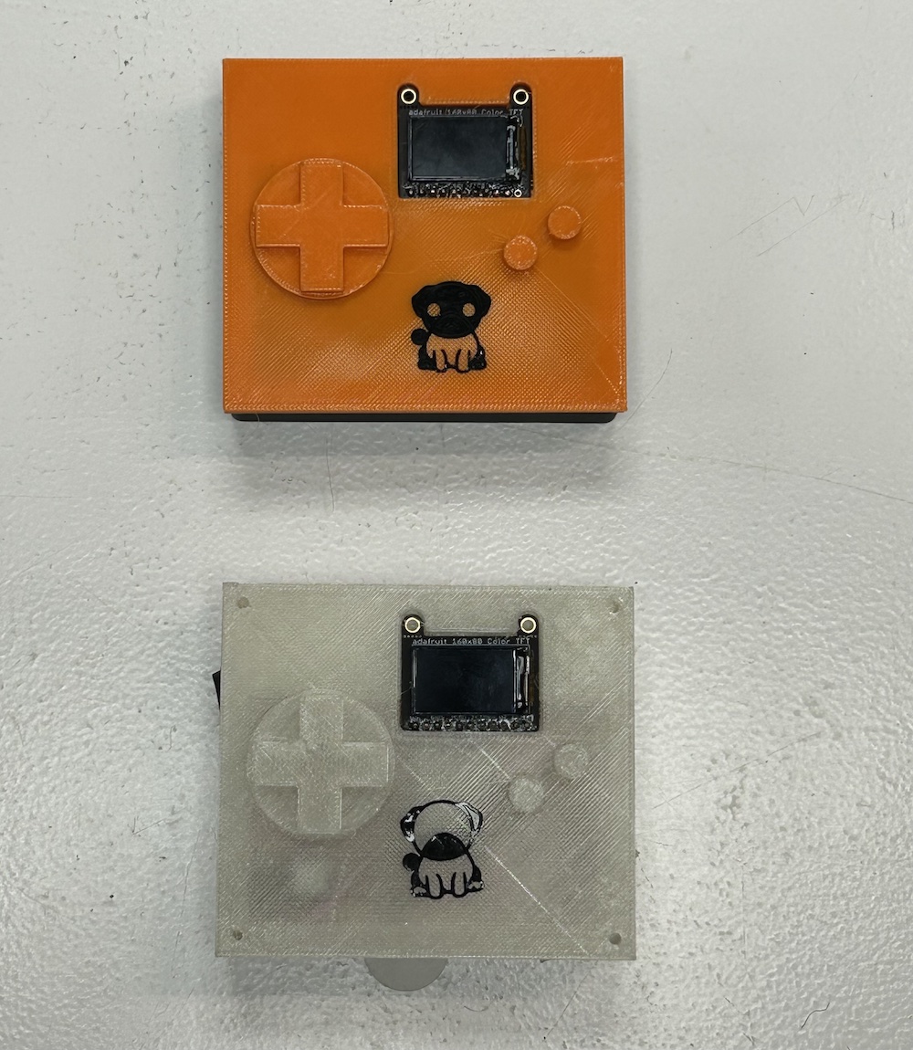
What does it do?
Currently only plays multiplayer or AI pong but more to come
Who’s done what beforehand?
Nintendo made a nice one
What did you design?
The PCB, the game and game engine logic, the 3D printed case. The vinyl cut logo was a chatgpt production. More can be read about in project development week.
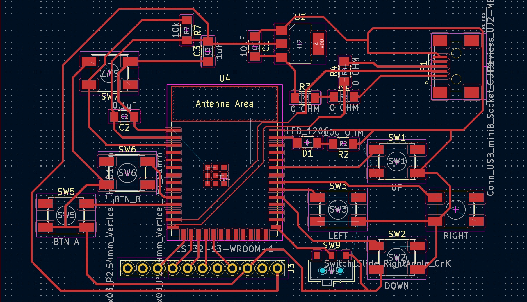
Bill of Materials
Where did they come from?
everything came from the lab. See above for real cost of parts.
What parts and systems were made? The 3D printed casing, the vinyl cut logo, and the PCB were all made. The pong game and its AIs were also programmed.
What processes will be used?
What questions were answered?
How to make a smooth(-ish) peer to peer gaming system. What types of processing power is needed and some of the important questions about frame refresh rate.
What worked? What didn’t?
The snapping mechanism to close the case didn't work well with TPU. I still haven't solved how to get the micro tensorflow model onto the board. Everything else worked fairly well- The screen worked much better with hardware SPI, the processing power has not been remotely tested or pushed to its limit.
How was it evaluated?
I played Pong and had others play. They LOVED IT.
What are the implications?
I can expand on the number of games and have some more fun.