Embedded Programming
Assignment 6 - Fab Academy Barcelona

This week I:
Quentorres Programming
First I programmed the Quentorres board using Arduino. The Quentorres board was produced in week 4.
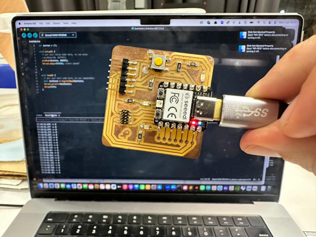
The below example adapts code provided in class. It reads the button state as input and prints a 1 if the button is pressed and a 0 if the button is not pressed. I played around with the delay to speed up and slow down the printing. Note: all code block formatting was generated with help of ChatGPT.
const int button = D1;

void setup() {
// put your setup code here, to run once:
pinMode(D0, OUTPUT);
pinMode(button, INPUT);
Serial.begin(9600); //sets speed?
}

void loop() {
// put your main code here, to run repeatedly:
bool butState = digitalRead(button);
Serial.println(butState);
delay(500);
}
You can see the output here - the "serial monitor" display at the bottom prints the output, you can see it change to 1 as I press the button.
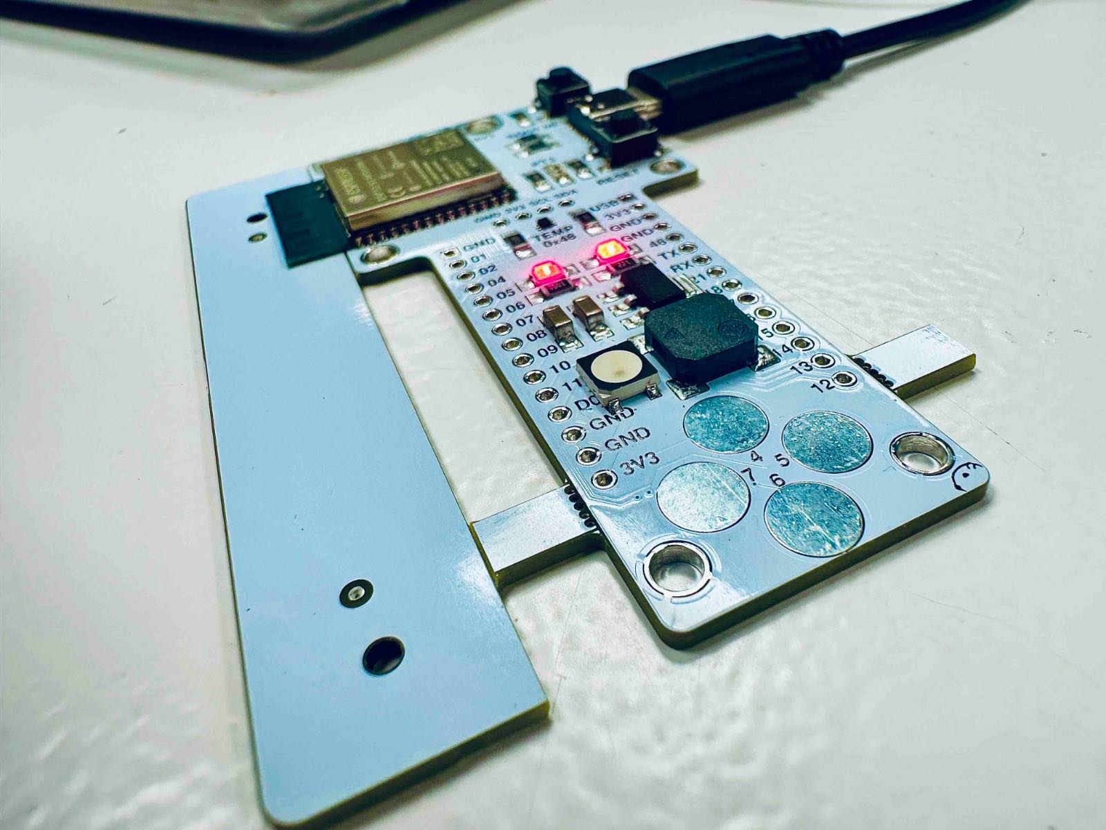
Barduino Programming from Examples
I then programmed the Barduino board, again in Arduino. I tried out 3 different programs, all taken from the Barduino examples library:
1. LED FADE
The LED fade program uses a digital system to model analog output. I updated the code to specificy the LED connected to pin 48. I initially ran the program as written in the example and successfully got the LED to dim on and off. I then changed the code to increase/decrease the fade amount and increase/decrease the delay to change the speed of blinking - increasing delay or decreasing fade amount slowed the dim speed. Decreasing delay or increasing fade amount increased the dim speed. For this and all examples below I updated the speed to match the microcontroller rate of 9600 (baud rate) which I found in Arudino's serial monitor.
SOURCE CODE
#include <ESP32Servo.h>

int led = 48;         // the PWM pin the LED is attached to
int brightness = 0;  // how bright the LED is
int fadeAmount = 5;  // how many points to fade the LED by

// the setup routine runs once when you press reset:
void setup() {  //void just means "function"
  // declare pin 9 to be an output:
  pinMode(led, OUTPUT);
}

// the loop routine runs over and over again forever:
void loop() {
  // set the brightness of pin 9:
  analogWrite(led, brightness);

  // change the brightness for next time through the loop:
  brightness = brightness + fadeAmount;

  // reverse the direction of the fading at the ends of the fade:
  if (brightness <= 0 || brightness >= 255) {
    fadeAmount = -fadeAmount;
  }
  // wait for 30 milliseconds to see the dimming effect
  delay(10);
}
Video of LED blinking :)
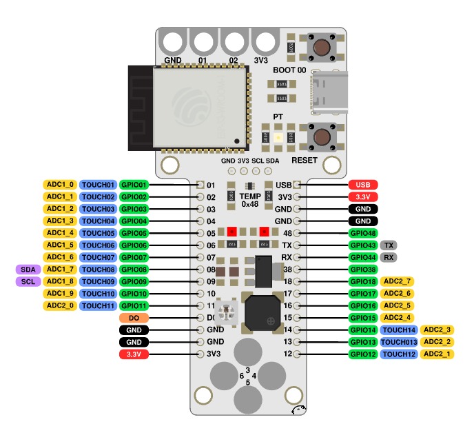
2. TONE
I really just ran the code as written, only changing the input pin to match the pin (14) connected to the Buzzer as indicated in the Barduino docs and Pinout. The code itself includes the ESP32Servo library, sets pin 14 as the pin the program will use. It then initializes the timers and sets baud rate. The loop function then plays a tone at 4186Hz for 500ms, then a tone of 5274Hz for 500ms. Then the program pauses (delay) for 500ms. FYI I used ChatGPT to help me understand this code using the prompt "please explain this code in plain English."
BARDUINO PINOUT
SOURCE CODE
#include <ESP32Servo.h>
int pin = 14;
void setup() {
    // Allow allocation of all timers
    ESP32PWM::allocateTimer(0);
    ESP32PWM::allocateTimer(1);
    ESP32PWM::allocateTimer(2);
    ESP32PWM::allocateTimer(3);
    Serial.begin(9600);
}

void loop() {
    tone(pin, 4186, // C
         500); // half a second
    tone(pin, 5274, // E
         500); // half a second
    delay(500);
}
Here's the tone program in action (SOUND ON!!!)
3. PWM
The PWM (Pulse Width Modulation) Example initializes use of the LED on Pin 48, initializes and sets frequency variable to 1000 Hz (number of times per second the PWM cycle runs), use of ESP32Servo library, allocation of Servo timers, baud rate, etc. In general I could not find good documentation on what is happening in the Setup statement, but ChatGPT was useful in deciphering the code.
The code continues with two "for statements":
- The first "for" loop increases brightness: it initializes brightness at 0, sets the condition that while brightness is less than or equal to 0.5, increase the brightness by .001. It writes the brightness (to output) and implements a delay of 2 milliesconds.
- The second for loop decreases brightness: it initializes brightness at 0.5, sets condition that while it's greater than or equal to 0 zero, decrease the brightness by -.001.
- There is then a pause implemented between the brightening/dimming cycle ("delay" after the two for loops).
- It also has a command that dynamically increases the frequency by 10 Hz each time the for loop runs (frequency here is the # of times the LED cycles thru on/off state per second to approximate analog dimming).
While I didn't expect the frequency change to be visible with the naked eye, it did change the appearance - in fact it made it appear as though the LED never fully went to a brightness of zero. I played around with the delays and frequency to create different patterns of brightening and dimming, and to better understand how each component contributed to the cycle.
SOURCE CODE
#include <ESP32Servo.h>
int APin = 48;
ESP32PWM pwm;
int freq = 1000;
void setup() {
  // Allow allocation of all timers
  ESP32PWM::allocateTimer(0);
  ESP32PWM::allocateTimer(1);
  ESP32PWM::allocateTimer(2);
  ESP32PWM::allocateTimer(3);
  Serial.begin(9600);
  pwm.attachPin(APin, freq, 10); // 1KHz 8 bit
}

void loop() {
  // fade the LED on thisPin from off to brightest:
  for (float brightness = 0; brightness <= 0.5; brightness += 0.001) {
    // Write a unit vector value from 0.0 to 1.0
    pwm.writeScaled(brightness);
    delay(2);
  }
  //delay(1000);
  // fade the LED on thisPin from brightest to off:
  for (float brightness = 0.5; brightness >= 0; brightness -= 0.001) {
    freq += 10;
    // Adjust the frequency on the fly with a specific brightness
    pwm.adjustFrequency(freq, brightness); // update the time base of the PWM
    delay(2);
  }
  // pause between LEDs:
  delay(1000);
  freq = 1000;
  pwm.adjustFrequency(freq, 0.0);    // reset the time base
}
Here's what happened when the code included frequency modulation in the dimming step - you see the LED never fully appears to extinguish.
Here's what happens when the frequency modulation is commented out - the LED appears to dim and brighten from fully off to bright at a regular interval.
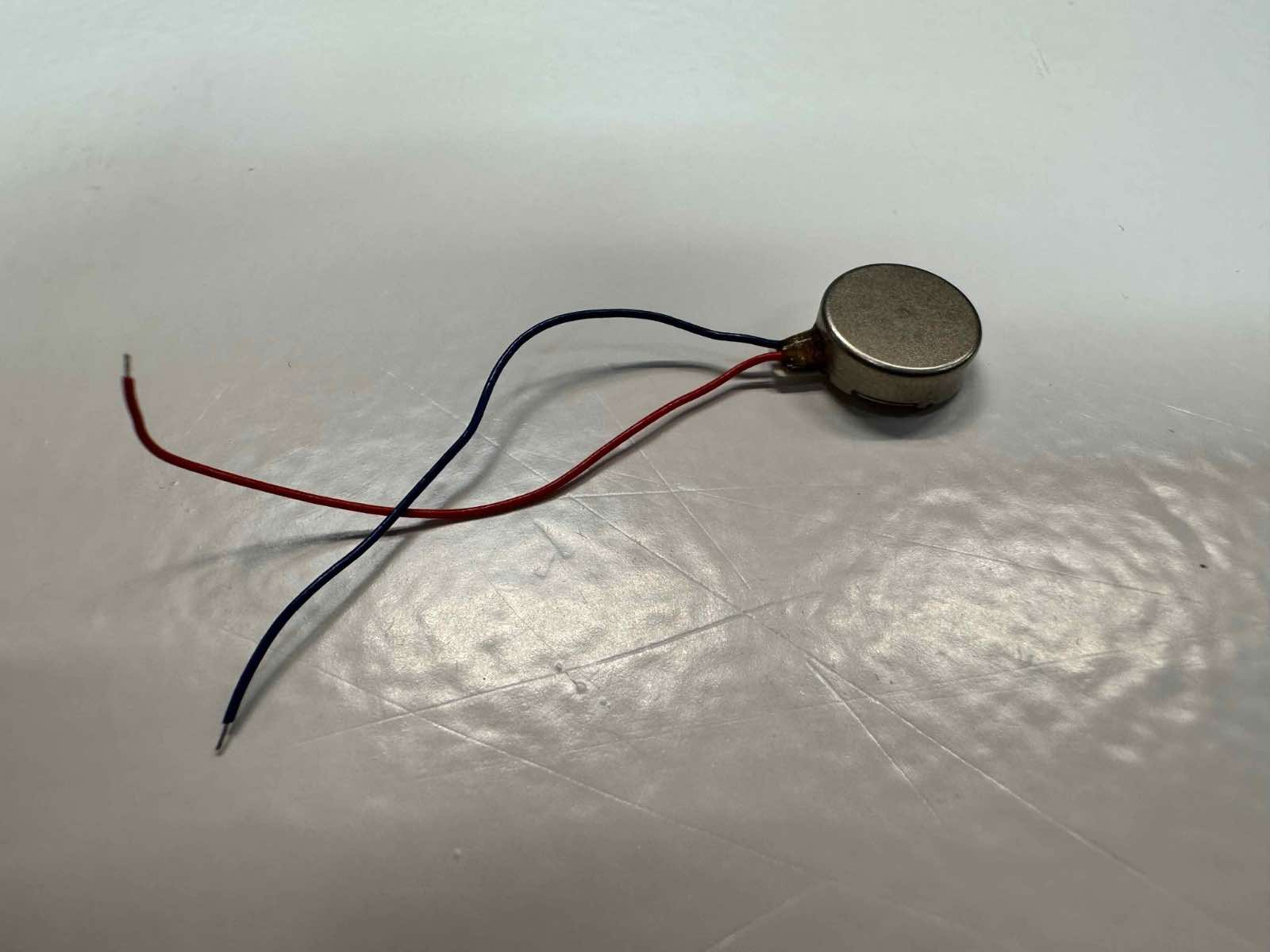
Starting to explore Haptics
My final project will require haptic motors as outputs, and so I started to explore these and will continue in the coming weeks. I'm currently working through this tutorial.
Haptic motor I found in the lab with the help of Julia and Adai.
Learning about Microcontrollers (Group Work)
This week's group work can be found here. We reviewed the datasheet for our microcontroller and examined other architectures.
Key takeaways on different microcontrollers (ChatGPT helped prepare this):
- ATtiny85: Best for simple, low-power applications like LED drivers or sensor interfaces, due to its simplicity and low resource requirements.
- ATSAMD11C: Suitable for intermediate projects needing higher processing power and USB connectivity, with a balance between capability and ease of use.
- ESP32: Ideal for advanced IoT projects with its high processing power, more memory, and built-in Wi-Fi/Bluetooth, offering wide development platform support.
- RP2040: Versatile for projects requiring custom I/O operations and supports a wide range of programming environments, lacking built-in wireless connectivity.