Electronics Production
Assignment 4 - Fab Academy Barcelona

This week I:
Creating a Printed Circuit Board
In class we were introduced to printed circuit board production and basics of electronics. We then made our own boards.
The first step is to generate the milling files (toolpath).
I followed this process:
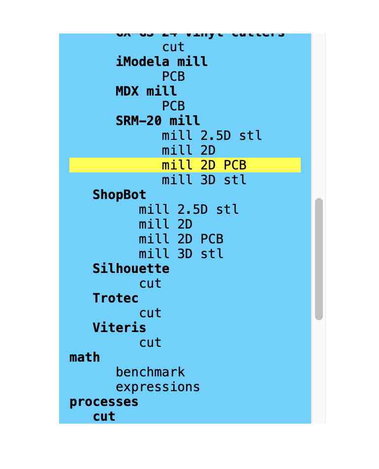
- Go to momodsproject.org
- Right click and go to Programs > Open Program
- Select SRM-20 mill > mill 2D PCB
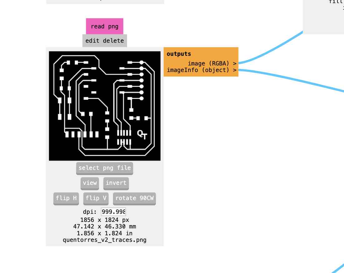
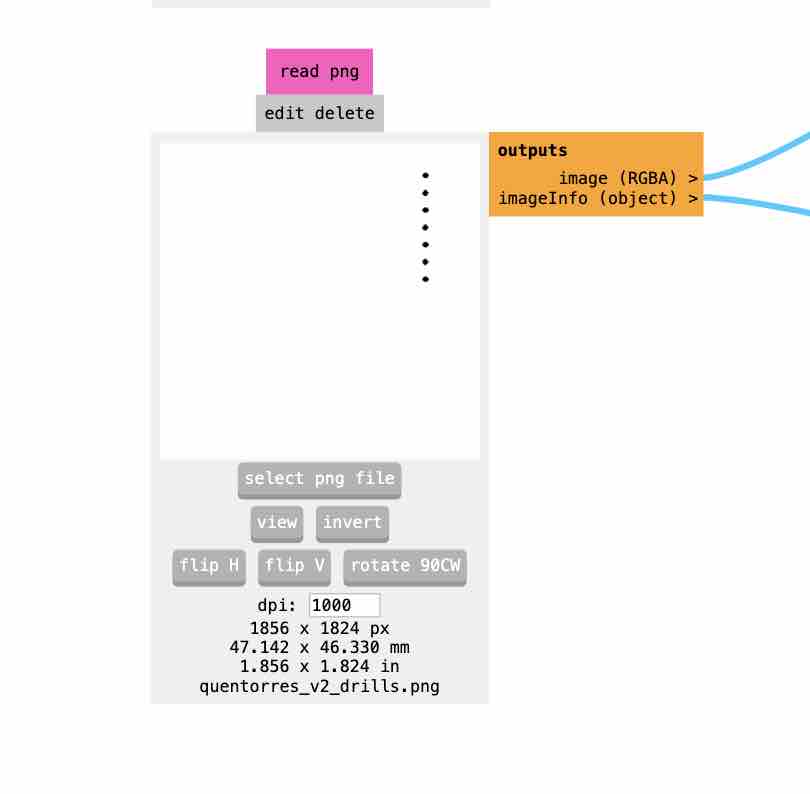
- Upload traces file found in assignment page on gitlab.
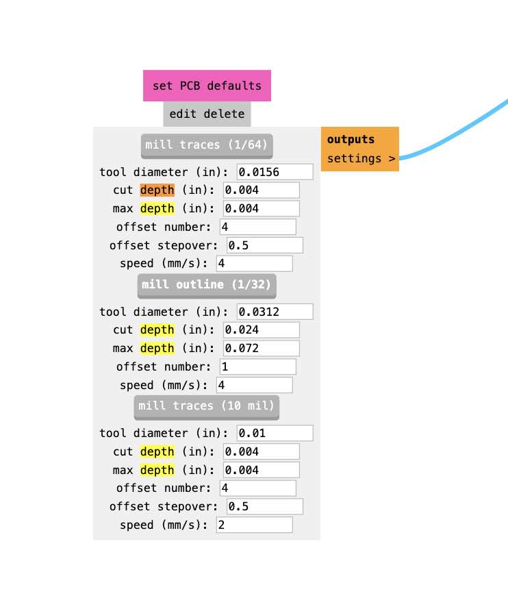
- Enter milling settings for traces cut by loading defaults for 1/64 bit
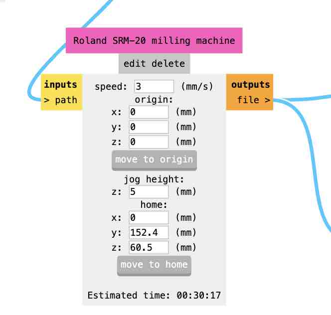
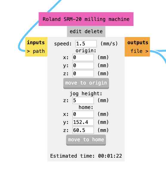
- Set speed to 3 and origin (0,0,0) as starting position. Set home to whatever you want, just MAKE SURE z setting is not zero or you will ruing your board and break the bit
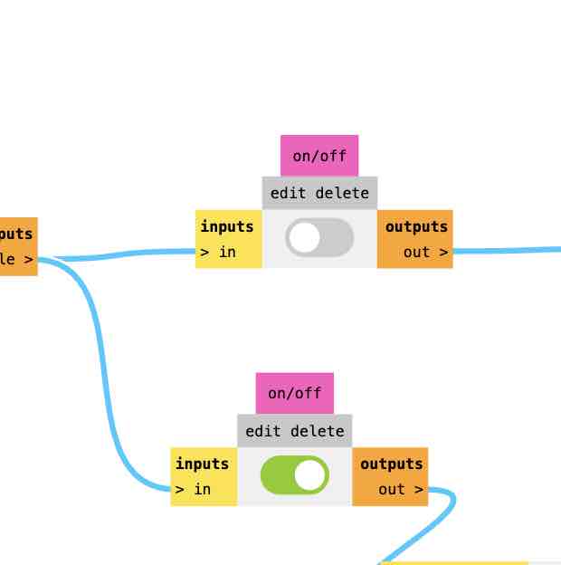
- Turn switches on and off
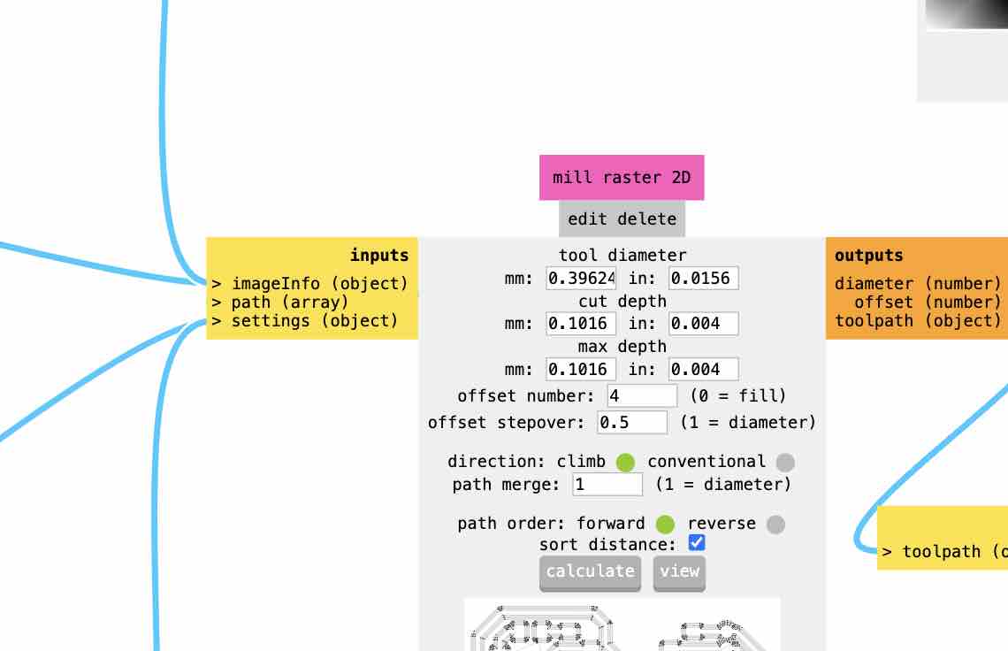
- On "Mill Raster 2D" module click "calculate" to generate milling file
- Upload to cloud to access on milling machine computer
- Repeat for Drill Holes - change settings accordingly: load 1/32 bit, change depth to 1.75 (in the "cut depth" and "max depth" in the "mill raster 2D" module, change speed to 1.5 (in the SRM-20 milling machine module).
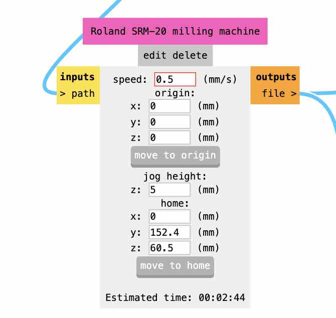
- Repeat for Outline: same settings as Drill Holes but change speed to 0.5
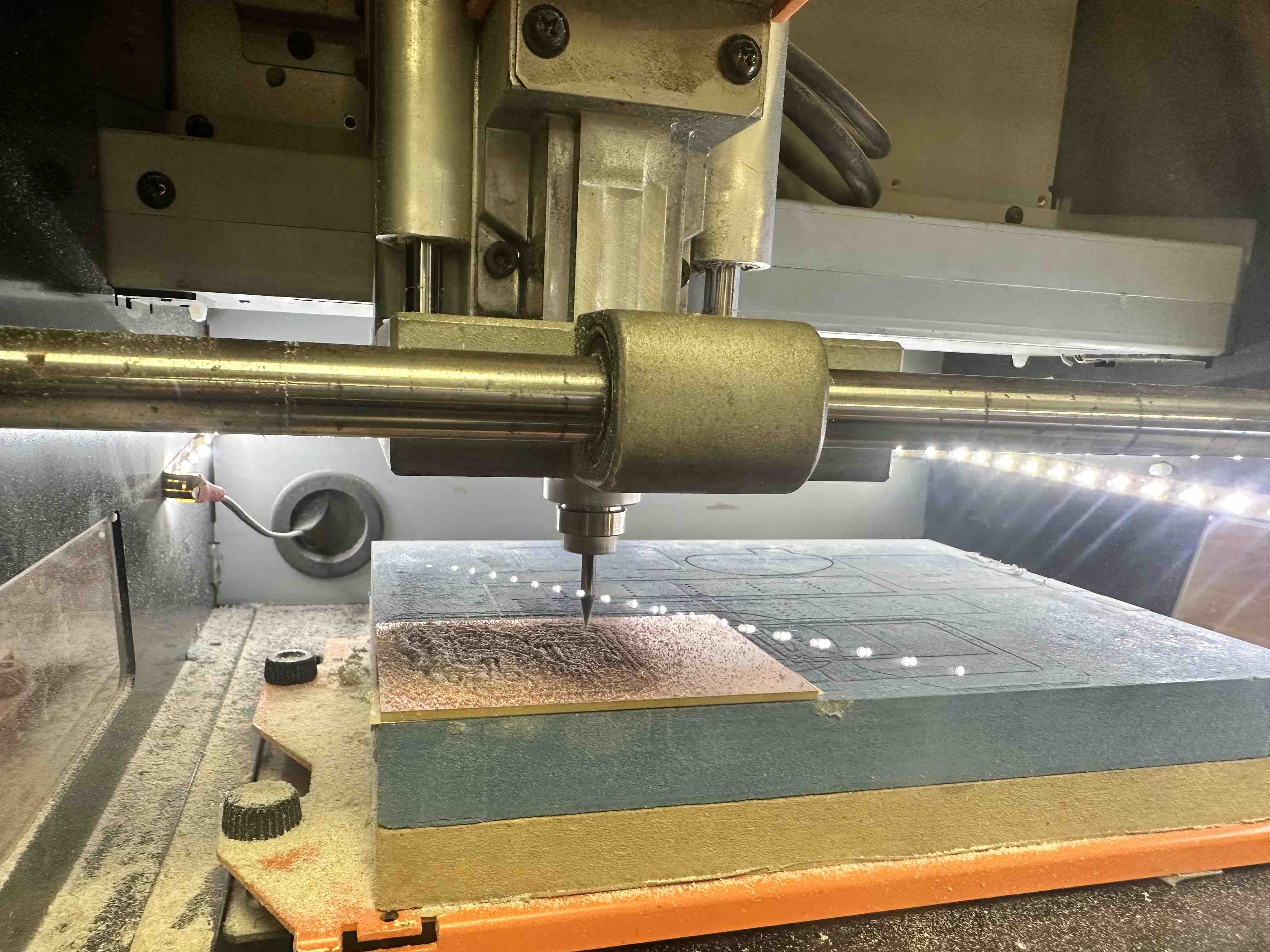
Then I milled.
I followed this process:
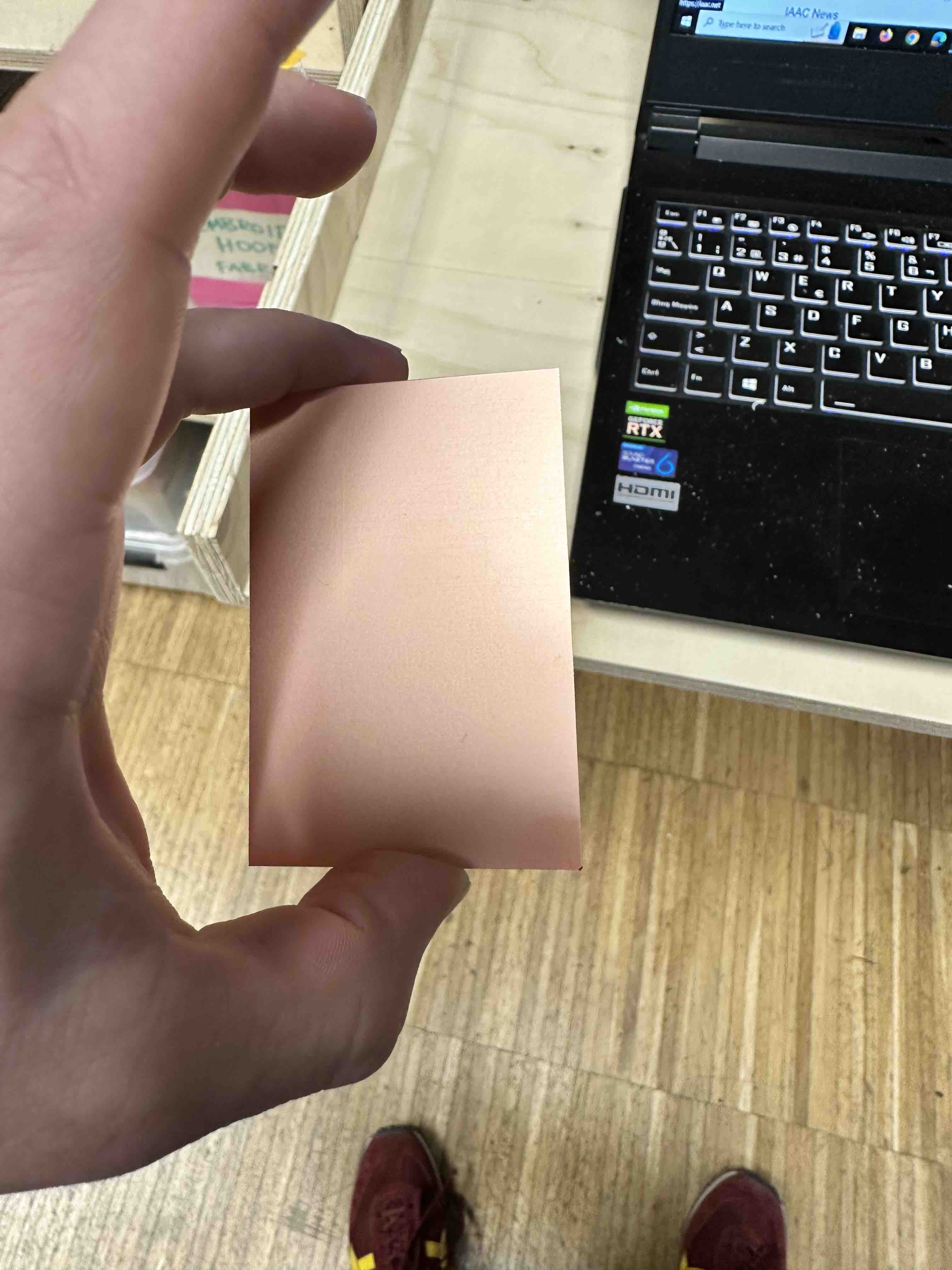
- Get fresh board
- Clean mill area (with brush).
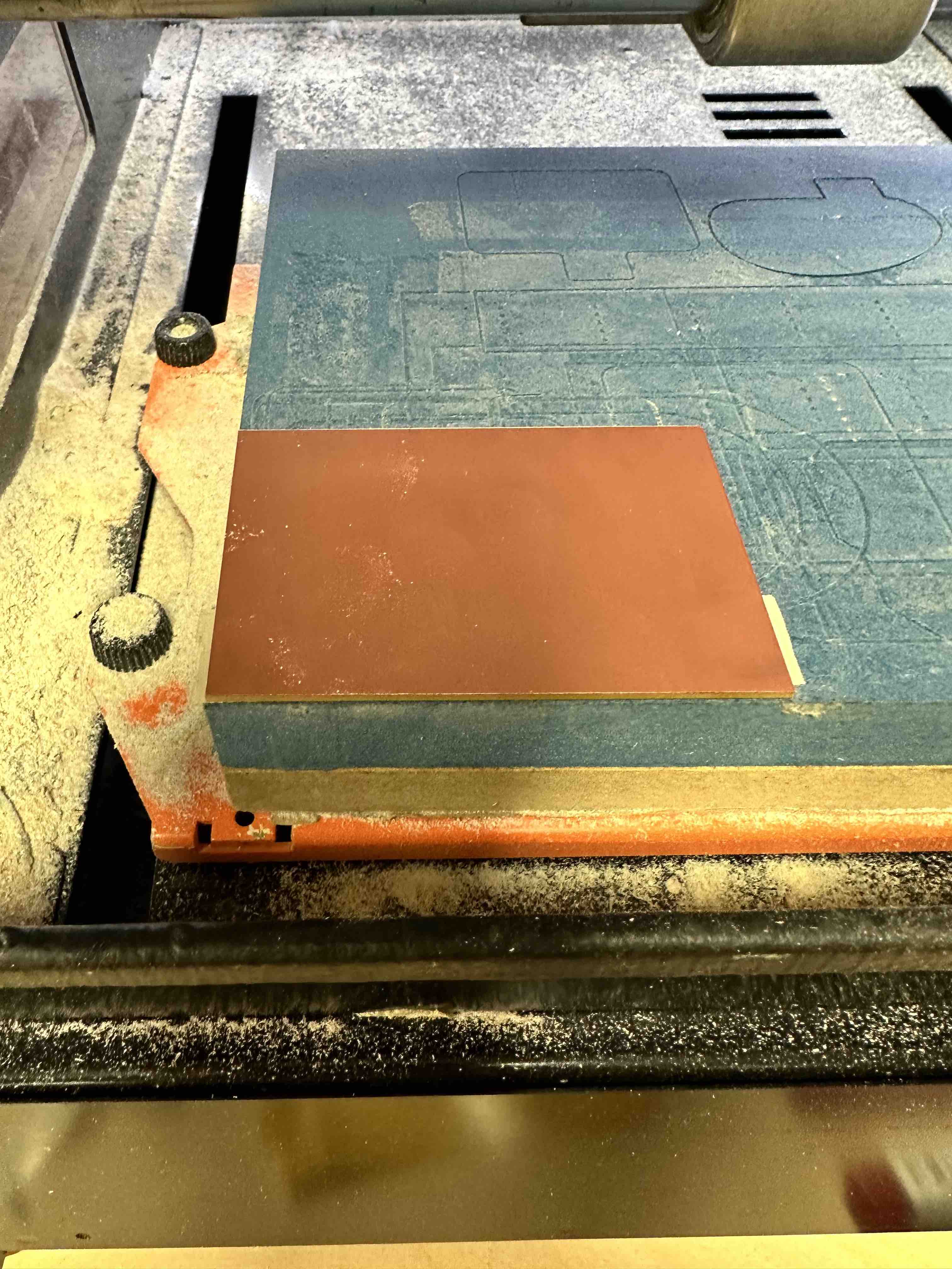
- Afix board to bottom left corner of milling area using double sided tape - push down tight. Make sure that it is flat! I ran into issues related to the fact that my board wasn't full flat at first (see Problems & Troubleshooting below).
- Change bit (if needed) - push bit high up in the machine (this will help with Z zeroing). Use wrench to tighten.
- Zero X and Y and click “x/y” button in program to set zero - you can do this by eye. Move using "continuous" setting to move faster.
- For Z NEVER set to continuous, move to just above the board and then loosen and let drop slowly.
- TIP: to fully zero z turn spindle “on” and set movement to 1, and slowly put z down until you here a change in sound / indication it’s actually milling, then set z to sero.
- Open traces file and press “cut” to start milling.
- Change bit to 1/32 and repeat for Drill and Outline files.
- Remove board, sand lightly to remove rough edges from milling.
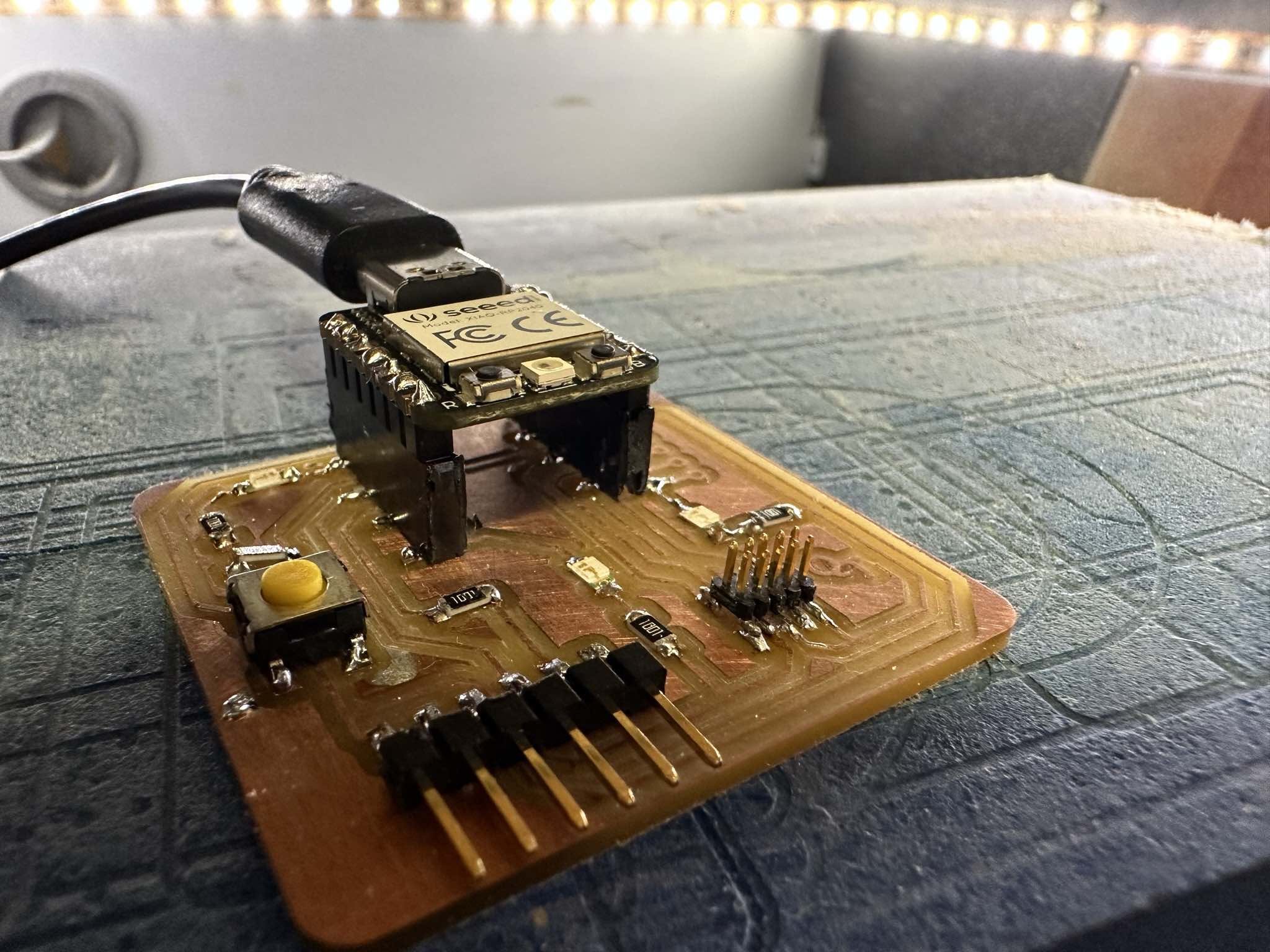
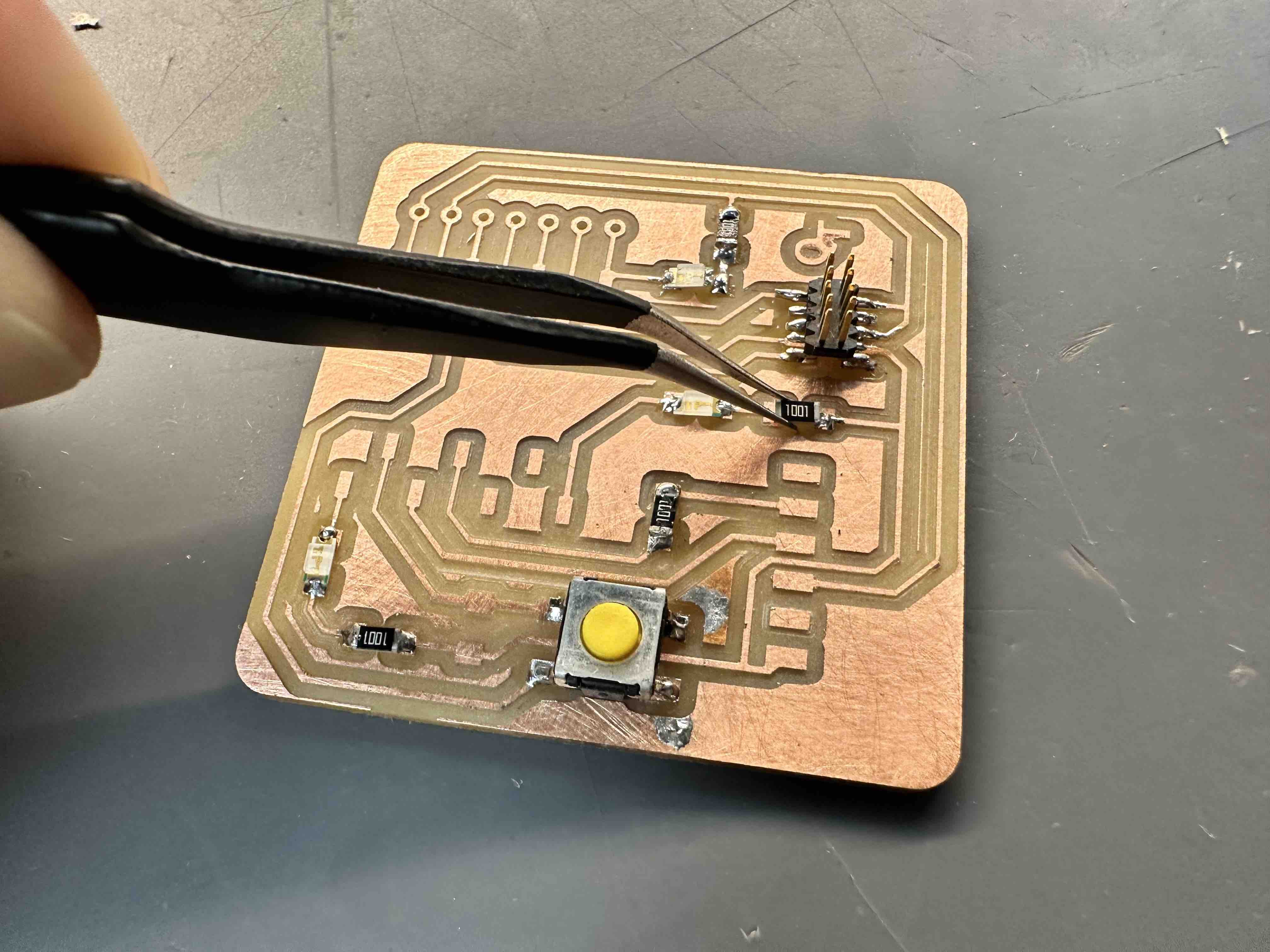
I then stuffed and soldered the board
I used solder wire and a solder machine at 400 degrees celcius, with a wet sponge and brass wool to clean the pen. I used a copper braid for desoldering.
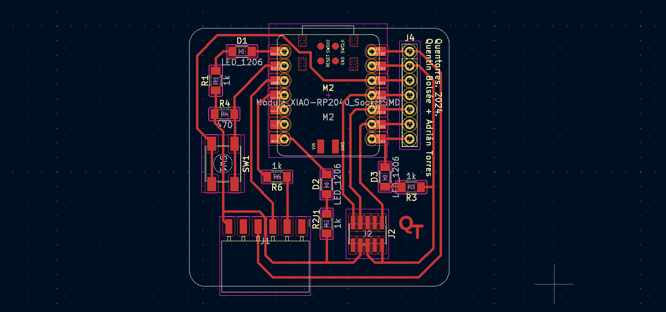
I started by soldering the smallest items including LEDs and resistors, with the Seeed component added last. As I have very unsteady hands I found soldering very difficult (I have a diagnosed, small tremor due to a condition called "essential tremor"). One of our instructors, Adai, gave me the tip of putting solder first on one of the contact points, then placing the component and heating it so that the first contact settles in. This holds the component in place while you solder the rest. I found this useful. I followed the below schematic to place the components.
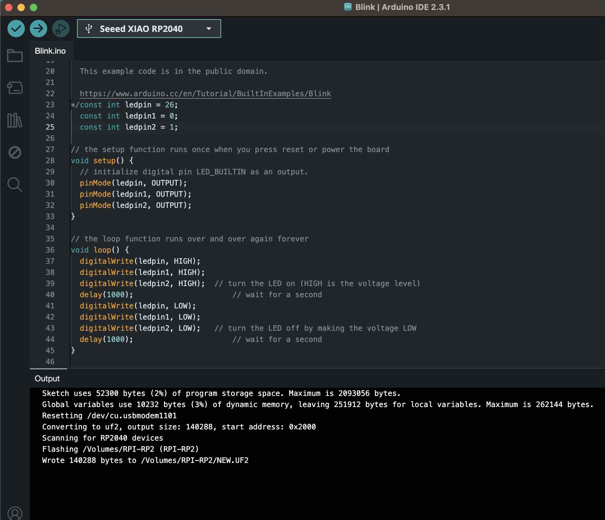
Programmed board and got it to work!
After completing the board production, I followed the instructions here in the section "How to use as a hello board" to download and install Arduino. With some help from classmates, I edited the blink program to reference the correct pins for each LED (see code below), then connected the board to my computer and uploaded the program.
At first only two LEDs lit (see Problems and Troubleshooting below), but after some resoldering all three lit up!
TWO LEDS WORKING
ALL THREE LEDS WORKING
Problems and Troubleshooting
I ran into 2 main problems this week. The first board I made was not level in the machine and the traces were not milled all the way thru across the board. I also faced some connection issues soldering.
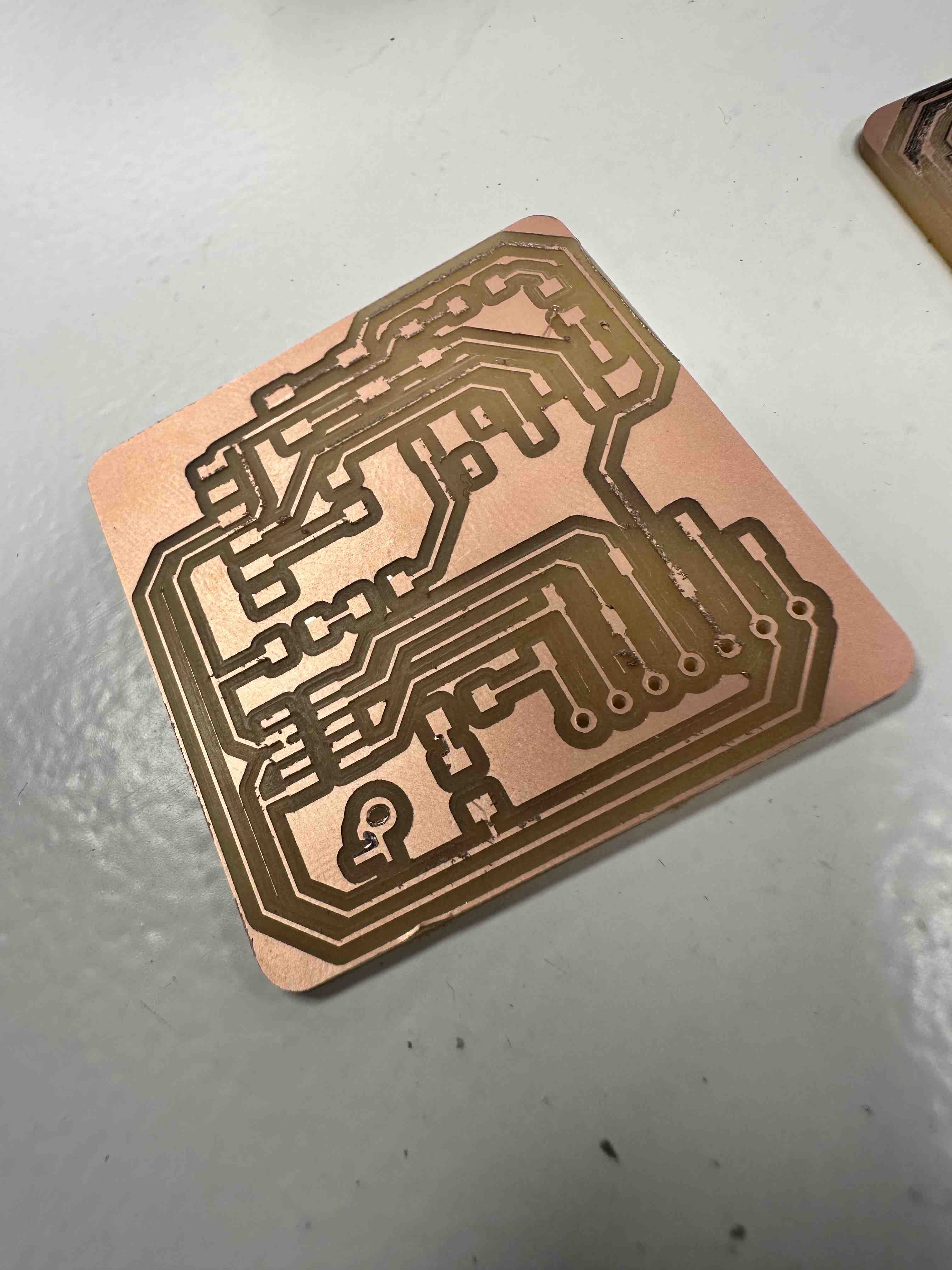
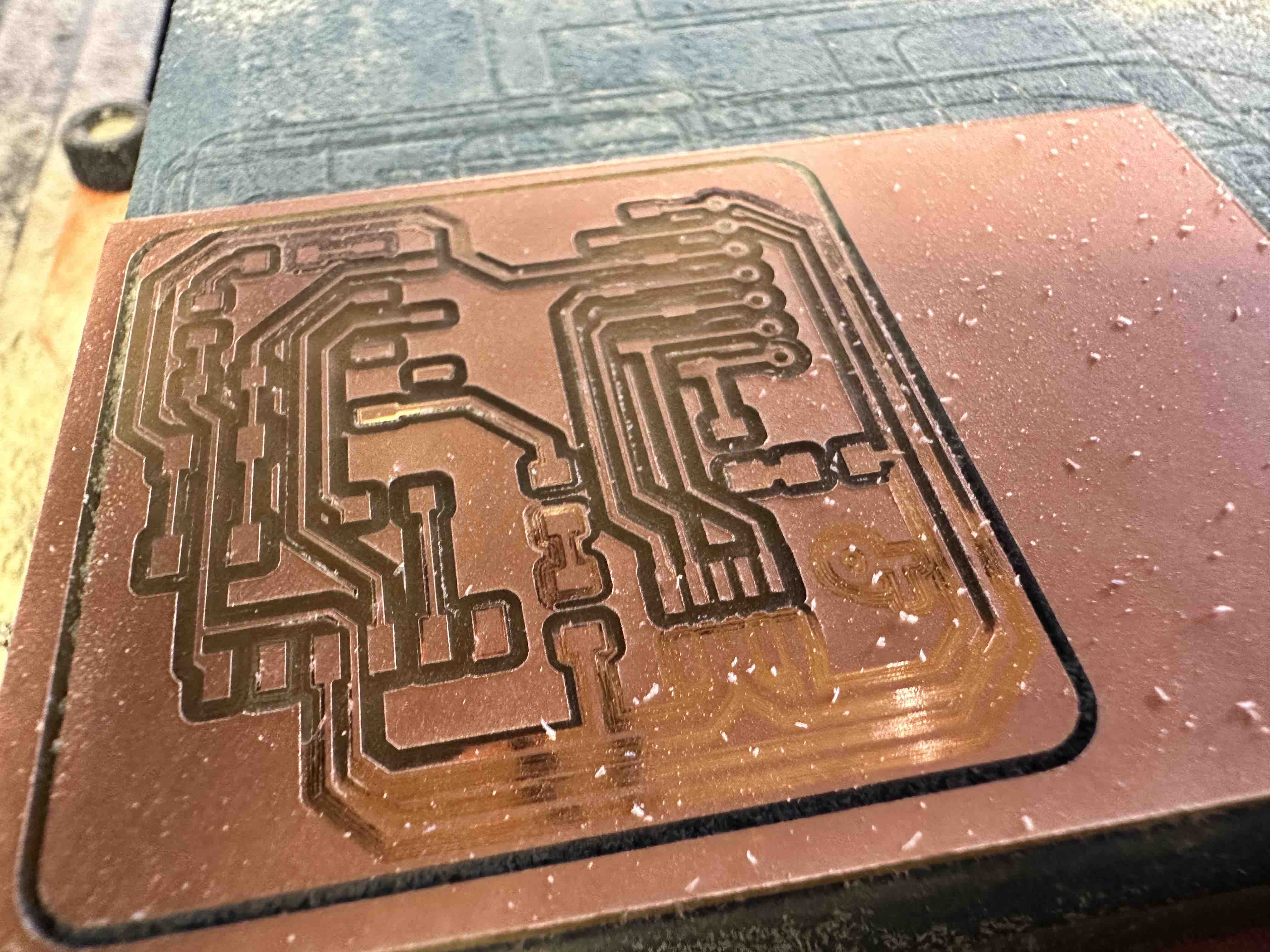
- TROUBLESHOOTING MILLING. My first attempt to mill traces didn't work - it did not mill all the way through the copper across the whole board. I believe it was due to the board not being level. I only put tape on two sides of the board. To ensure my second attempt was level, I put more tape so that the whole bottom of the board was covered and pressed firmly down. See below for my failed attempt. You can see the traces milled closest to the camera still have a layer of copper.
- BREAKING THE END MILL. I broke an end mill. I was setting the z zero and after I was done, I went to move the bit back up. However instead of moving in the z direction I moved in the y direction (both are indicated by up arrows on the machine) and the bit broke. Lesson learned to move slowly and double and triple check when operating machines.
- TROUBLESHOOTING SOLDERING. Other than unsteady hands and some burns, I also failed at connecting all the LEDs correctly the first time. I didn't realize that there needed to be solder OVER the top of the LED connectors (I thought it was sufficient to have solder underneath). I added more solder to fix the issue.
Files Created / Sourcecode
- Traces Milling File (RML)
- Drill (Holes) Milling File (RML)
- Outline Milling File (RML)
- Arduino Source Code
Group Assignment
This week's group assignment was to characterize the design of our in-house PCB production process in Barcelona with the Rolad SRM 20 Mill. We'res also supposed to send a PCB out to a board house. For me, the group project served as a useful first exposure to the milling process, allowing me to see the key steps and participate in some of them. However, I found it much more useful to go through the individual milling and PCB assignment so as to have the full end-to-end experience.
Our group assignement documentation can be found here.