Week 9: Output Devices
This week I tested the connections of my board (how my board was designed and fabricated) and programmed it to do some simple functions. I worked in a group to control a motor and measure its draw. Our group documentation can be found here.
In the group assignment I learned how to use a multimeter to measure the power and current draw of an output device. I also learned how much the current draw changes depending on the strain put on the motor.
Using my microcontroller to do stuff
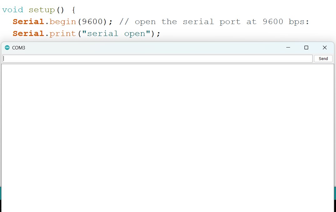
Serial monitor not working
At the start of the week I planned to use a rotational encoder module, (a dial with a button), and a LCD to create a user interface that I might incorporate into my final project.
I got stuck troubleshooting issues with the serial monitor, not realizing that the board I was using only works with a bit rate of exactly 115200.
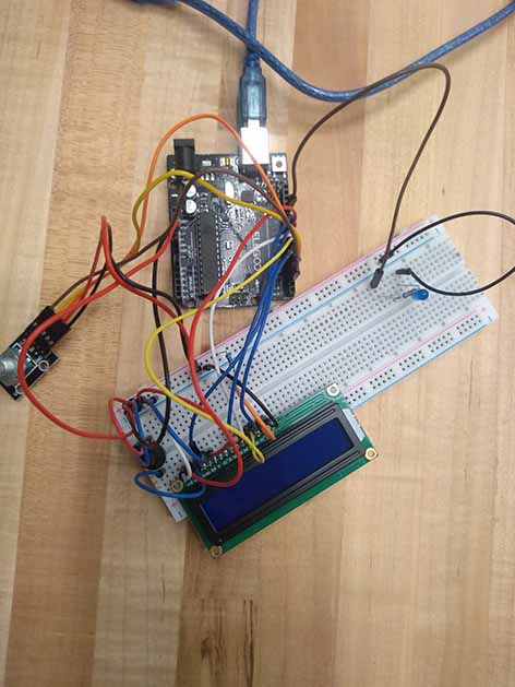
LCD to replace serial monitor.
On the Arduino Uno, I used and edited some sample code I found online to try to extract user input from the REM. I managed to get clear input from the rotation of the RTC, but the direction and button were not working in the code that I had adapted. The serial monitor outputted some random characters mixed with pieces from other strings in my code whenever anything was outputted to the serial monitor. These inclusions happened seemingly at random making me think there must be some sort of connection issue.
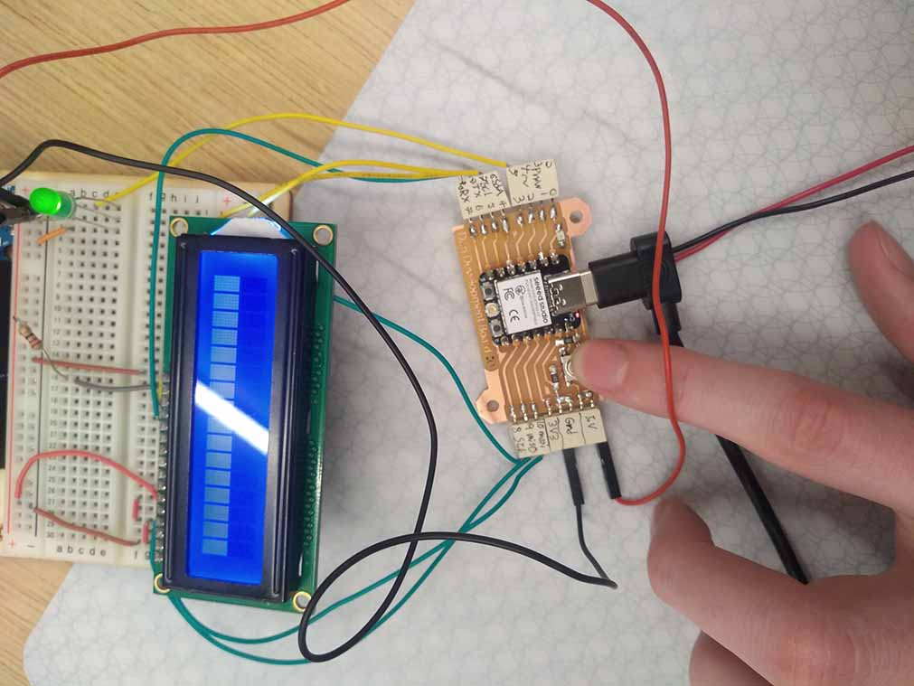
I gave up on the REM for the time being and tried to get the LCD connected to the ESP32.
I found that the pin numbers for the esp32 are actually numbered from 2-7, 21,20,8-10. Instead of 0-10. Knowing this, I was able to get the LCD working, and I used it to aid me in debugging.
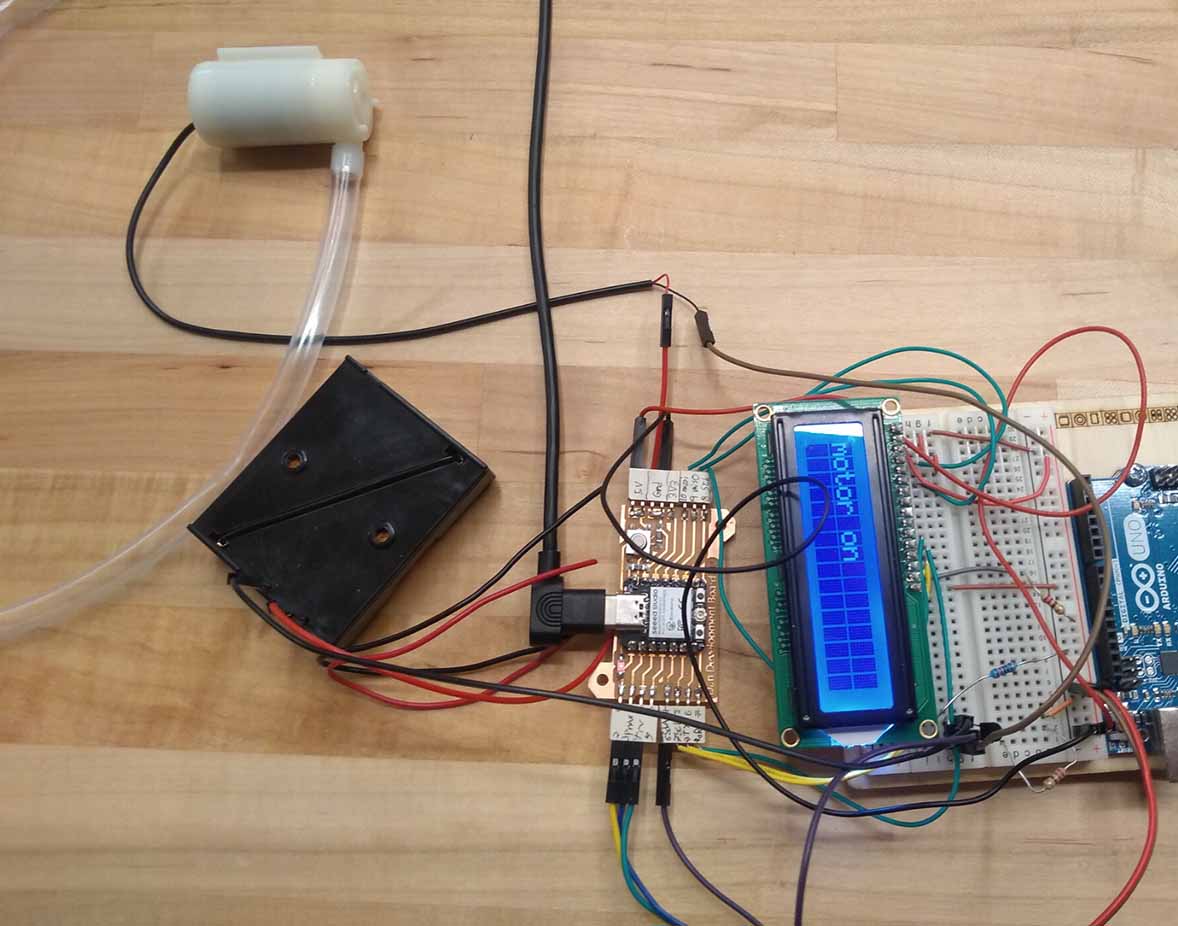
Pump
I designed a circuit in tinkercad to get an understanding of transistor wiring. I learned about adding a diode in the opposite direction of the transistor to protect the transistor from the voltage created by the motor after the transistor is shut off. I also heard it is better to place the transistor in the ground wire, though I don’t know the reason. I used the microcontroller to toggle the pump motor on or off and display the state of the motor on the LCD screen. I used the button I built into my board as a means of toggling.
Circuit diagram
I used a 2N2222A transistor for toggling the pump. Here is a circuit diagram for controlling the pump with the transistor. If you need a wiring diagram for the LCD screen, see my see my week 4 documentation.
It sets up an LCD connection using the LiquidCrystal library, then switches the motor on and off when you press a button. It prints messages to the LCD screen to indicate when the output pin is on or off.
        #include
        LiquidCrystal lcd(9, 10, 8, 20, 21, 7);

        int ButtonPin = 6;  //HIGH when button pressed.
        int poPin = 5; // potentiometer analog input pin

        bool motorState = 0;
        bool buttonState = 0;

        int counter = 0;

        void setup() {
          lcd.begin(16, 2); // Set up the number of columns and rows on the LCD.
          lcd.setCursor(0,0);
          lcd.print("Hello world");
          pinMode(ButtonPin,INPUT);
          pinMode(poPin,INPUT);

          pinMode(2,OUTPUT);
        }

        void loop() {
          if(digitalRead(ButtonPin)==HIGH){ // if the button has been pushed
            if(!buttonState){ // then if the button wasn't already pushed
              buttonState=1;   // record it as being pushed
              lcd.setCursor(0,0); // move cursor to position 0,0
              if(motorState){    // if the motor was on
                digitalWrite(2,LOW); // turn it off
                lcd.print("motor off         "); //print to lcd
                motorState=0;   //record the motor as being off
              }else{   //otherwise
                digitalWrite(2,HIGH); // turn it on
                lcd.print("motor on          "); //print to lcd
                motorState=1;   //record the motor as being on
              }
            }
          }else{ // otherwise record that the button is not pressed
            buttonState=0;
          }
          delay(1);
        }
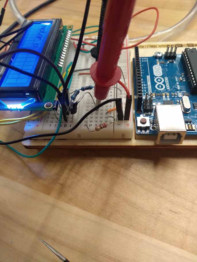
Transistor working unreliably
I used a thermistor to detect the heating of the transistor and found that when the base of the transistor is being powered, it heats up rapidly. I tried using a resistor to lower the voltage to the base, but it also lowered the speed of the motor. This goes against my understanding of transistors. The setup worked with very low reliability. I found that if I shorted the transistor while it should have been on anyway, it would start to allow current through like it’s supposed to and stop heating up. I also found that the transistor works more reliably once it has heated to around 60 degrees celsius. It seems like this may be due to the transistor malfunctioning, but I got similar results with other transistors. I might update this in the future if I learn the cause of this issue. Later I found that mosfet transistors work much better for this purpose