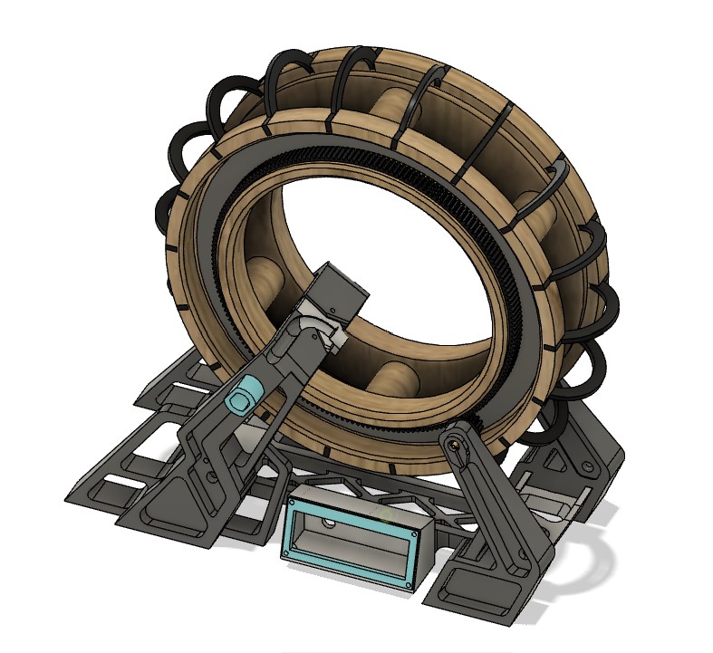
I created a 3D model in Fusion 360 for week 2, modified it later when I made the first prototype, then modified it further for the latest prototype.
Final Project: Moss Ring
Concept
The original idea for this design was a kinetic sculpture moss garden with an LED strip bright enough to light a room. I started with a large number of potential features I might want to add, and then cut out features that I deemed less important and time consuming. I initially intended to create a magnetic levitation and propulsion system for the rotating ring, but settled on a wheel in track design for practical reasons. I used photoshop to create an initial concept art of what it might look like. I wanted to go for an overgrown sci-fi aesthetic.
Slide
Video
Here is the fusion design file: [ Download ]
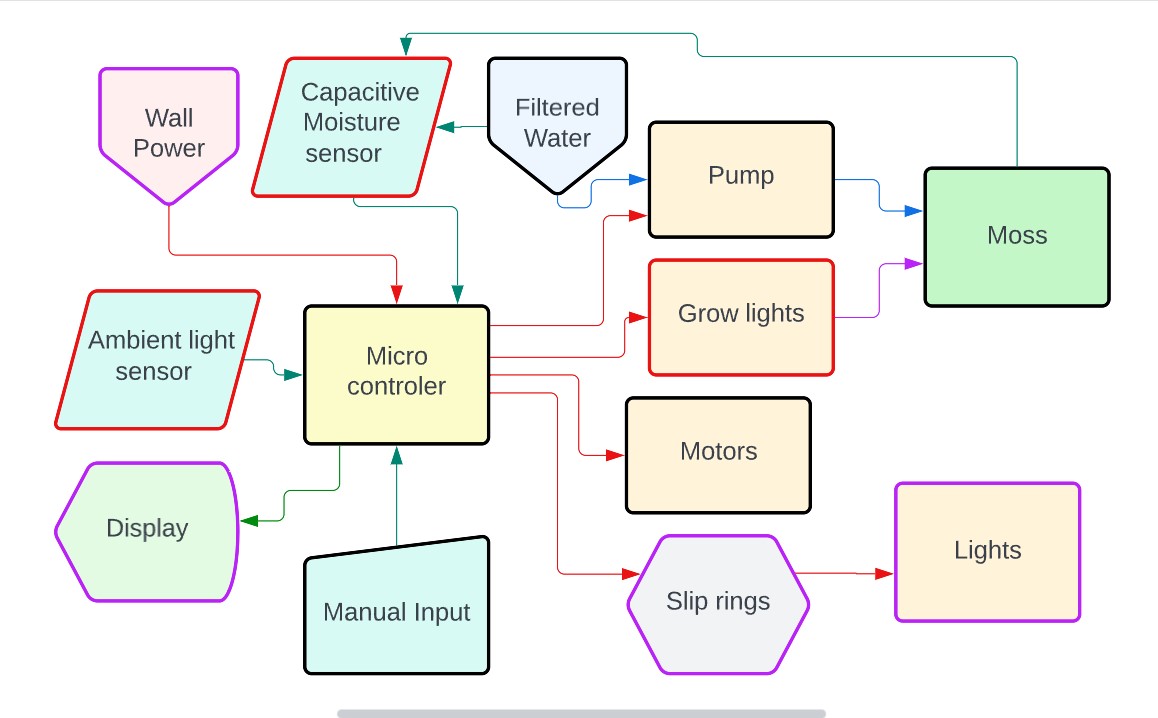
Once I had an idea for the features and structure of my project I created a flowchart to visualize how power and data would flow through the system.
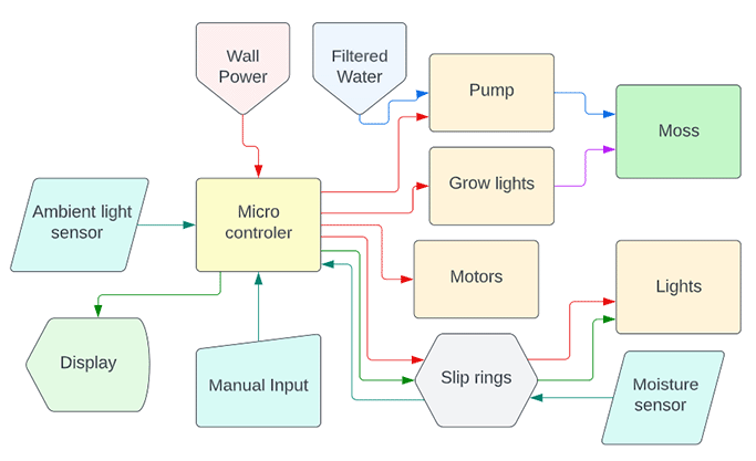
Later on, I realized that the slip rings would probably not be able to transmit data reliably, so I decided to use normal LEDs instead of NEO Pixels for the light ring. I also moved the moisture sensor onto the base of the design, and I hoped to be able to determine the moisture level of the soil with a parallel-plate capacitor. The black, purple, and red outlines indicate the first, second and third stage of development for the project.
The wheel
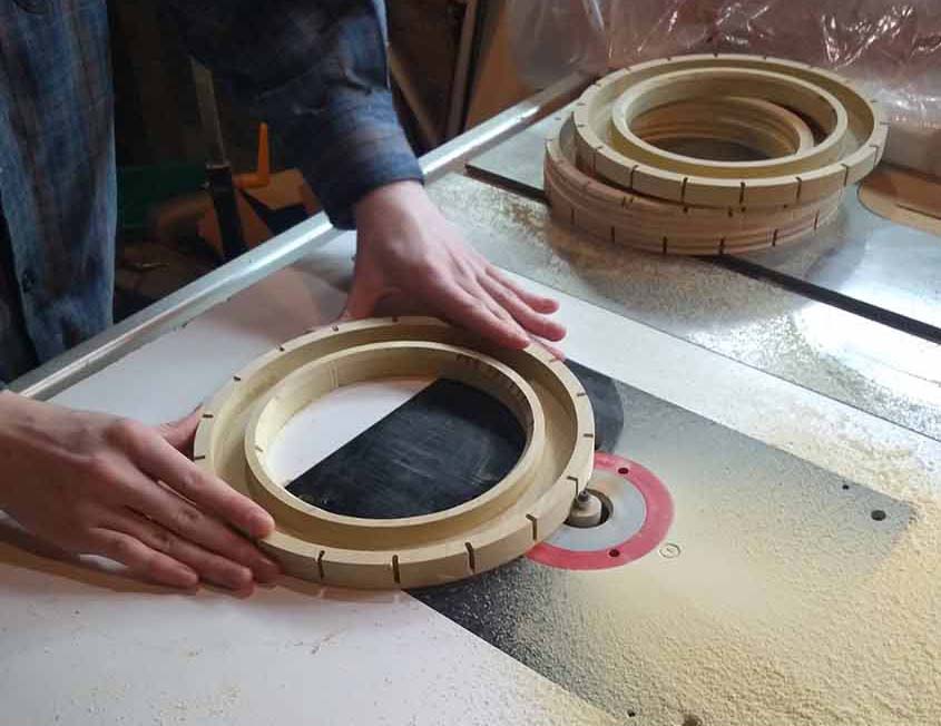
I went back and forth on how I would make the wheel for the moss to grow on. It needed to be something strong and resilient enough to hold the soil and water. The size of the wheel would make it difficult to 3D print, though I did make a model that could work for 3D printing it in smaller sections. I considered casting it in a large 2-part mold, but the cost of the wax blocks was relatively high, and I wasn’t sure if the silicone mold would be able to hold its shape well enough while holding the seam tight enough. I was also concerned about the roughness of the cut, as many of the wax molds I had seen were too rough for a smoothly rolling track. The simplest and easiest option was to mill the two wheel halves with a CNC machine and attach them together with pillars. I decided to go with the CNC option partly due to time considerations. Wood seemed like the easiest option for milling, though I have some concerns about it staying together once there is damp soil in it. I sourced a board of poplar from home depot. I tried birch plywood first, but the voids in the wood were problematic for the project.
CNC mill
The wheel was cut with 4 separate toolpaths. The first was a pocket toolpath to carve out the support wheel channel. The second and third were profile toolpaths to cut out the middle and outside of the torus respectively. The final toolpath was another outside profile cut, except with a ⅛ in bit instead of a ¼ in bit. This final cut was for the purpose of cutting the notches for the ribbing to slot into the side of the wheel. The channel made by the ⅛ in bit is the same as the thickness of the acrylic sheet that I made the ribbing out of.
I don’t have the original toolpath files anymore,
but you can recreate it in Vcarve using these vectors: [ Download ]
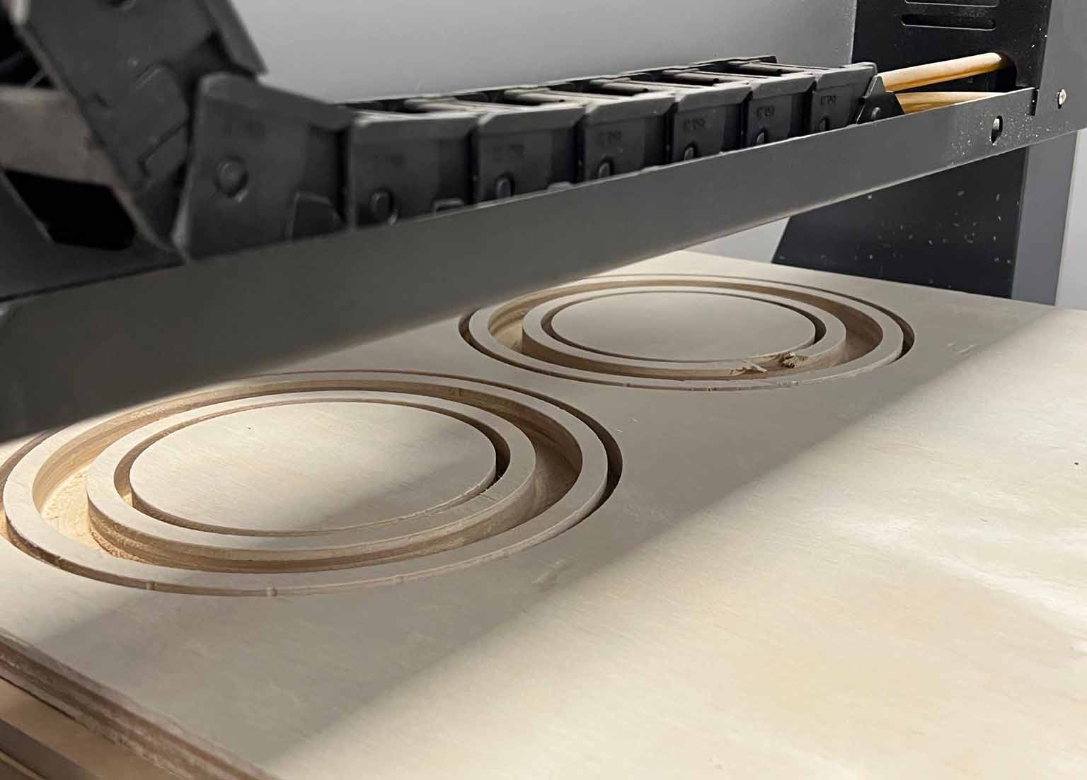
Table router
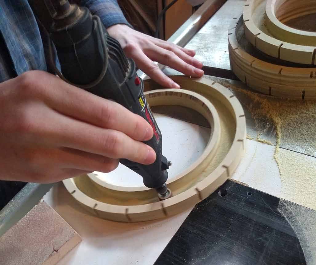
After cutting the tabs and sanding, I used a table router to finish the shape of the wood. I Started by using an edge cut bit, with a roller the same diameter as the cutting edge. This made it easy to remove the ridge that was left at the bottom of the cut. Next, I used a 45 degree chamfer bit to bevel a few different corners of the wheel. Finally, I used a groove router bit to cut into a different edge, to reveal the bottom of the ⅛” notches.
To smooth out the channel, I used a dremel with a sanding head. I kept it on low speed so as to not dig into the material too much.
Laser cutter
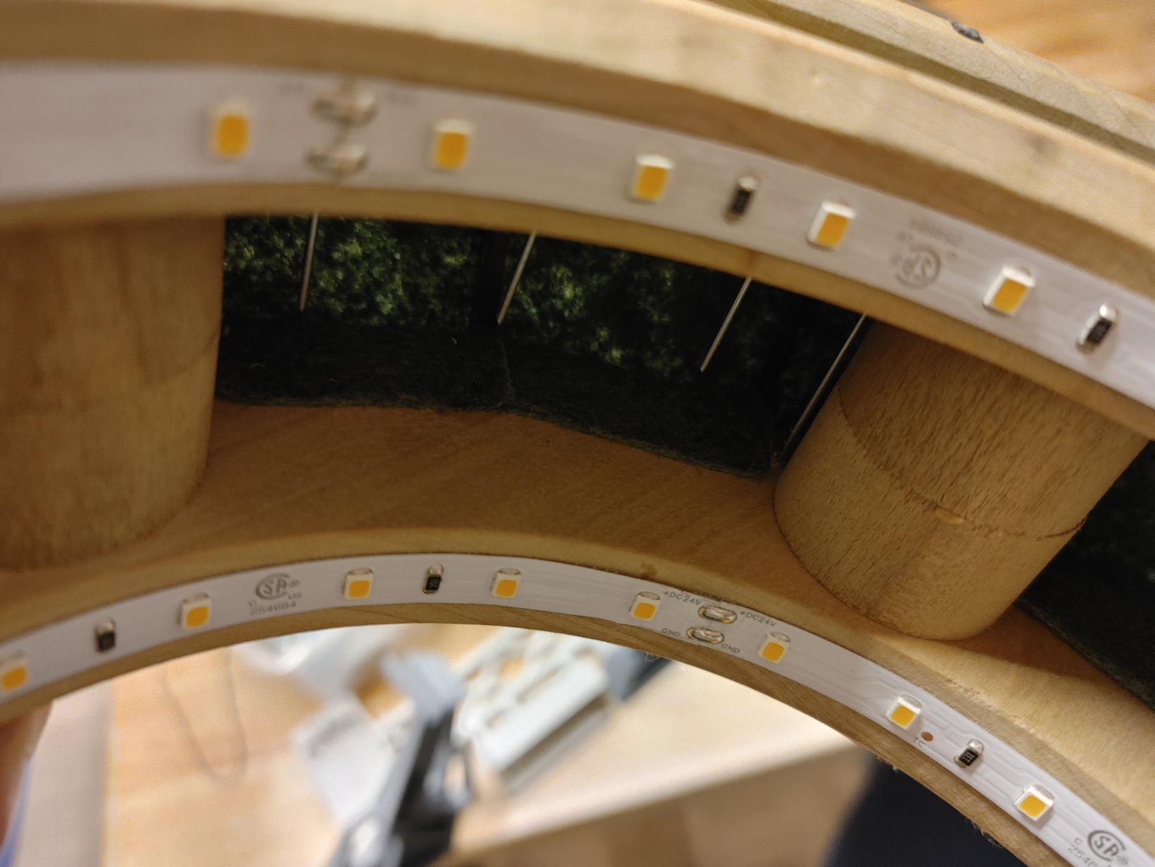
I cut the acrylic ribbing and the felt sheets using a laser cutter. To prepare the ribbing for laser cutting, I created a sketch on the face of one of the pieces of ribbing, and saved it as a .dxf file. I opened that file in illustrator, and then cut it out to test the tolerance of the part. I used this test to tweak the dimensions slightly, and then made a pattern of all 18 that could fit in a small area.
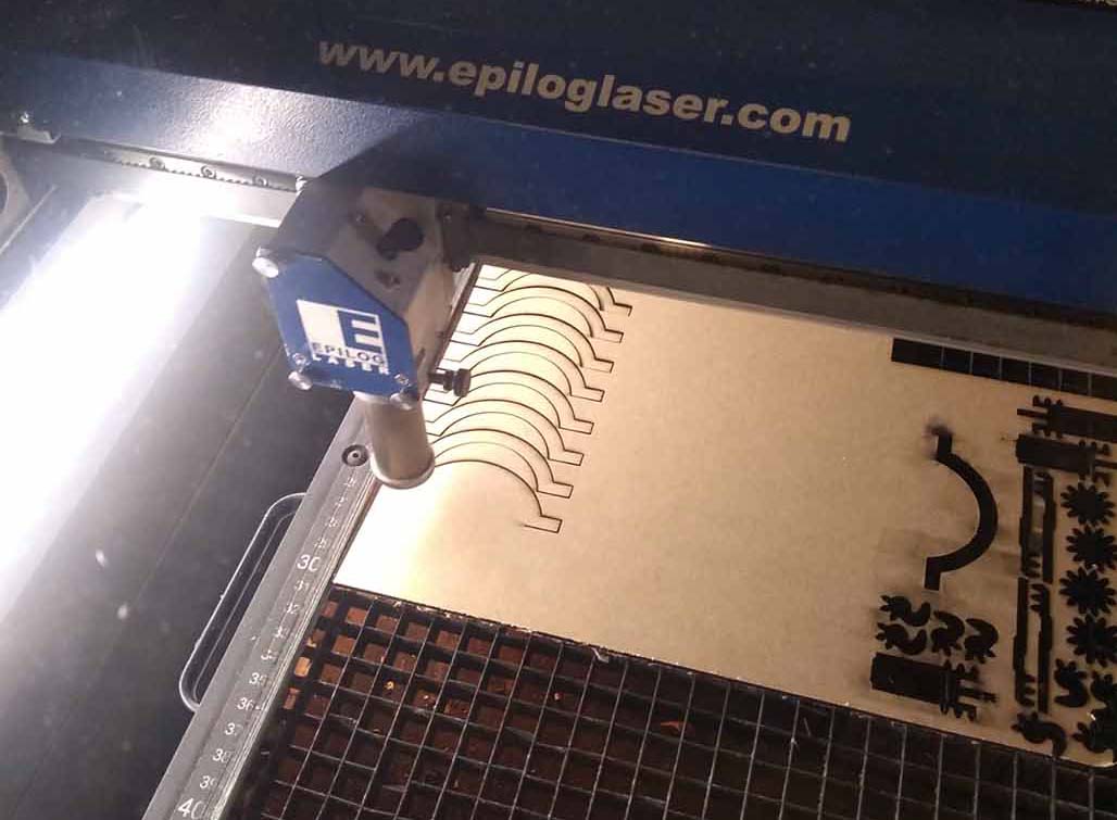
Here is the illustrator file for the ribbing: [ Download ]
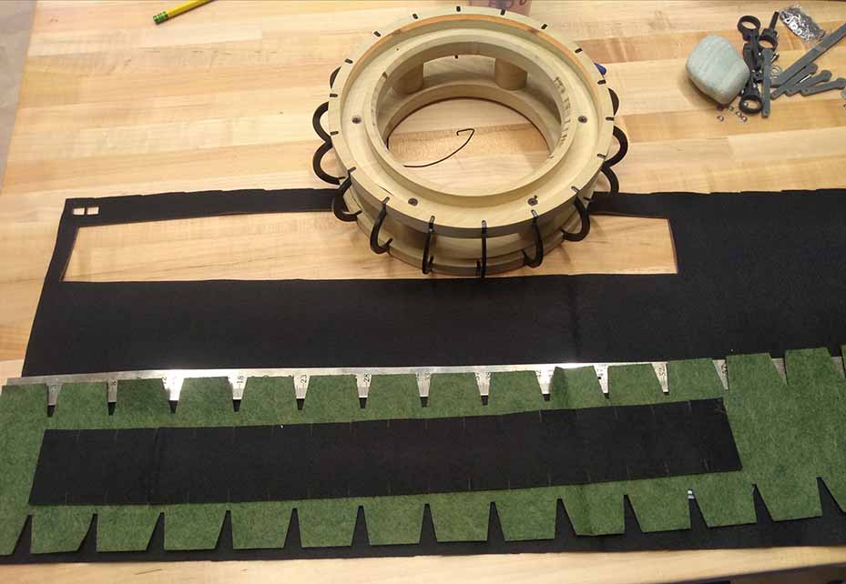
felt
For the felt, I rolled the wheel across the piece of felt and then measured the distance of 1 complete roll to determine the actual circumference of the wheel including the ribbing. I then made a sketch in fusion 360 for both the inside and the outside felt soil coverings.
Here is the illustrator file for the felt: [ Download ]
Wheel assembly
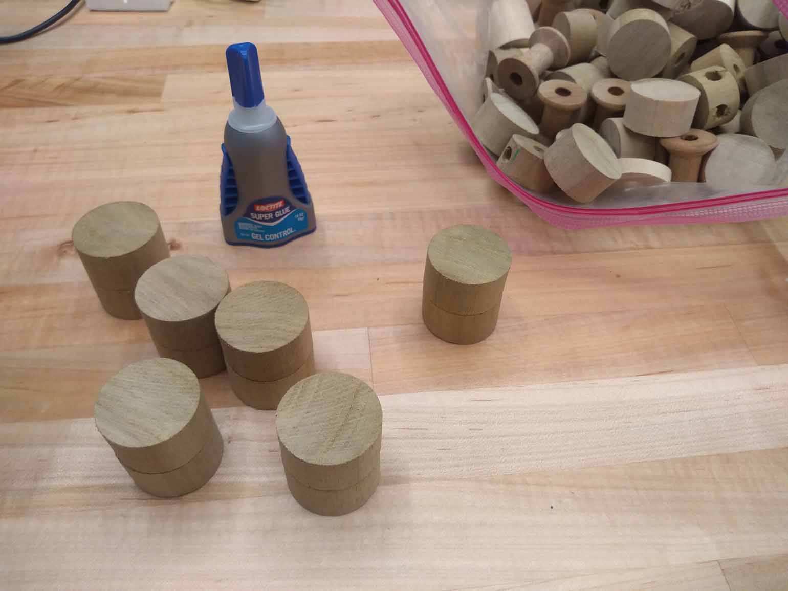
Once I Had the ribs and the wheel halves, I found some small wood blocks for spacing the two halves of the wheel apart. I held them together with superglue, and then clamped them into place.
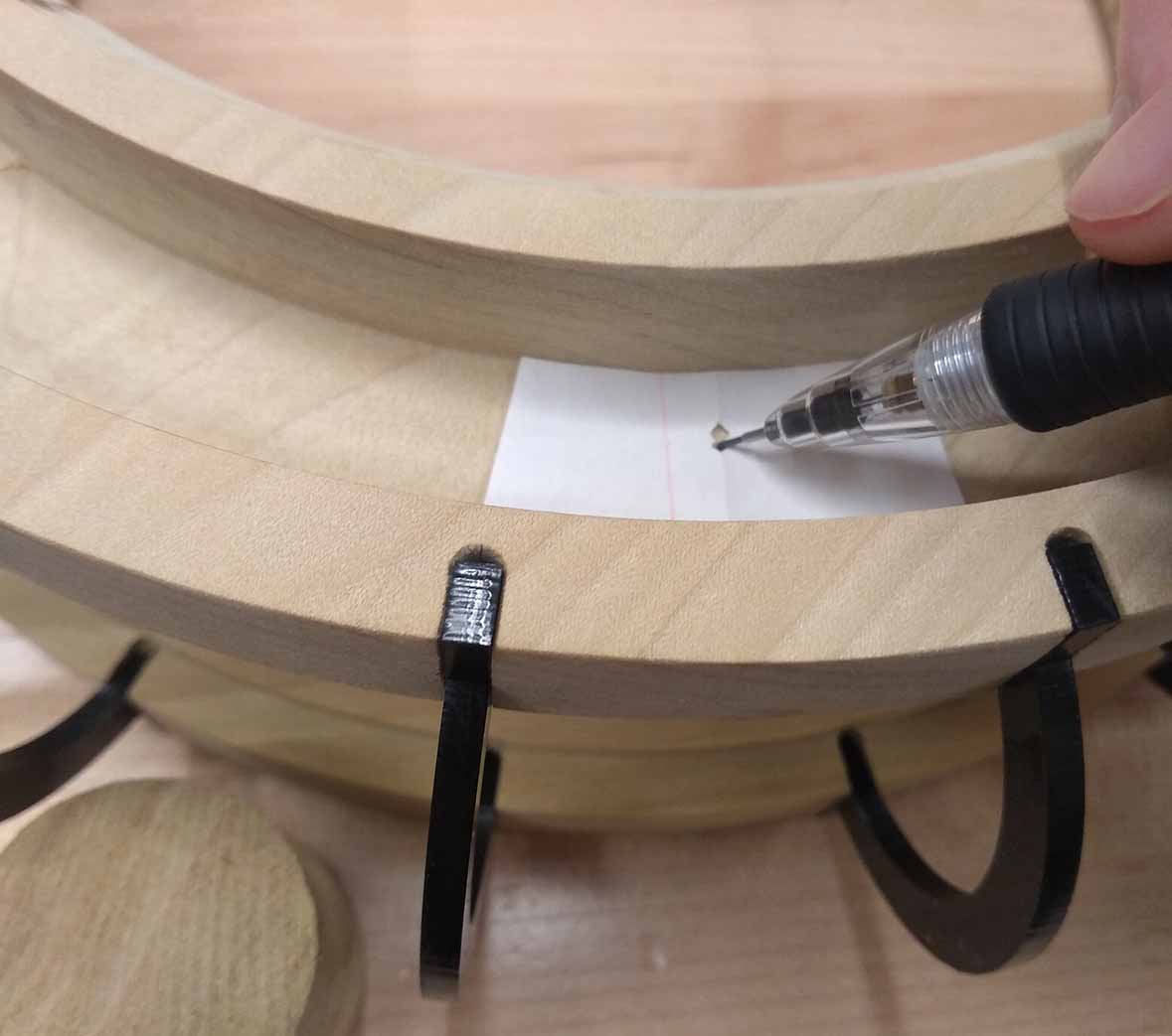
I used a piece of paper to mark the positions for the screws. I made them offset from the center of the blocks so that they wouldn’t collide inside the wood. This also made room for the holes for the wires to go through.
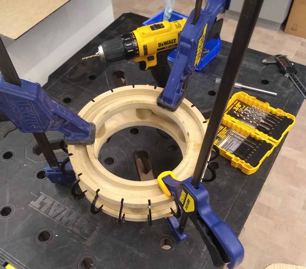
Drill
I used a drill to make pilot holes for the screws, and then I used an angled bit to create a counter sink so that the heads of the screws wouldn’t stick out too far from the floor of the channel.
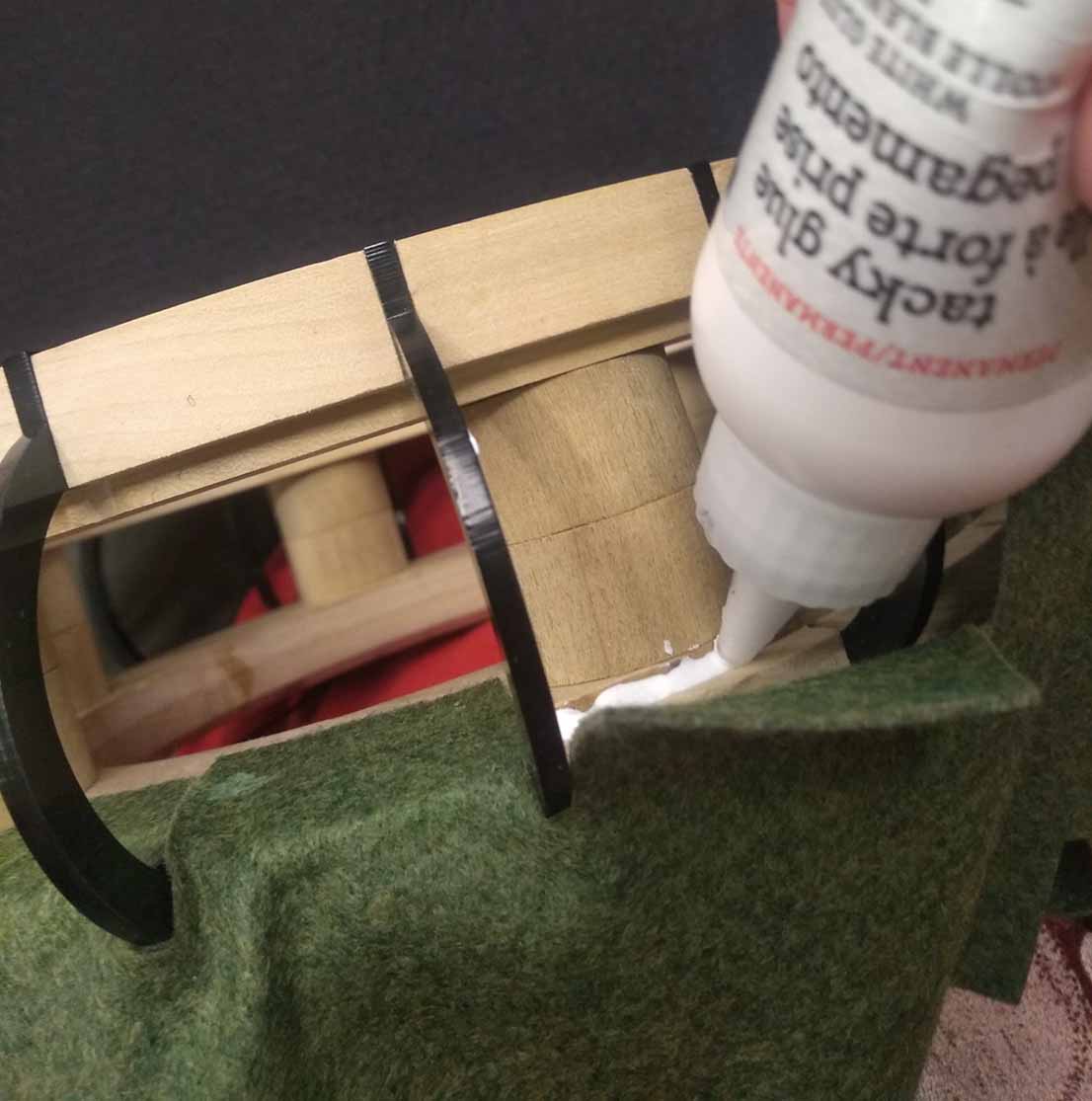
Glue
The next step was gluing. I used superglue to secure the ribbing in place, and Tacky glue to secure the felt to the wood. I did the felt one side at a time because gluing the second side would involve pulling the felt over the ribbing and putting negative pressure on the bond.
Slip rings
To maintain electrical contact with the wheel while it’s spinning, it needs slip rings. I bought an aluminum plate at home depot to cut into slip rings. I laser cut a template out of cardboard, and used it to trace the outline of the slip rings onto the aluminum sheet. I then used metal scissors to cut out the rings following the line by hand.
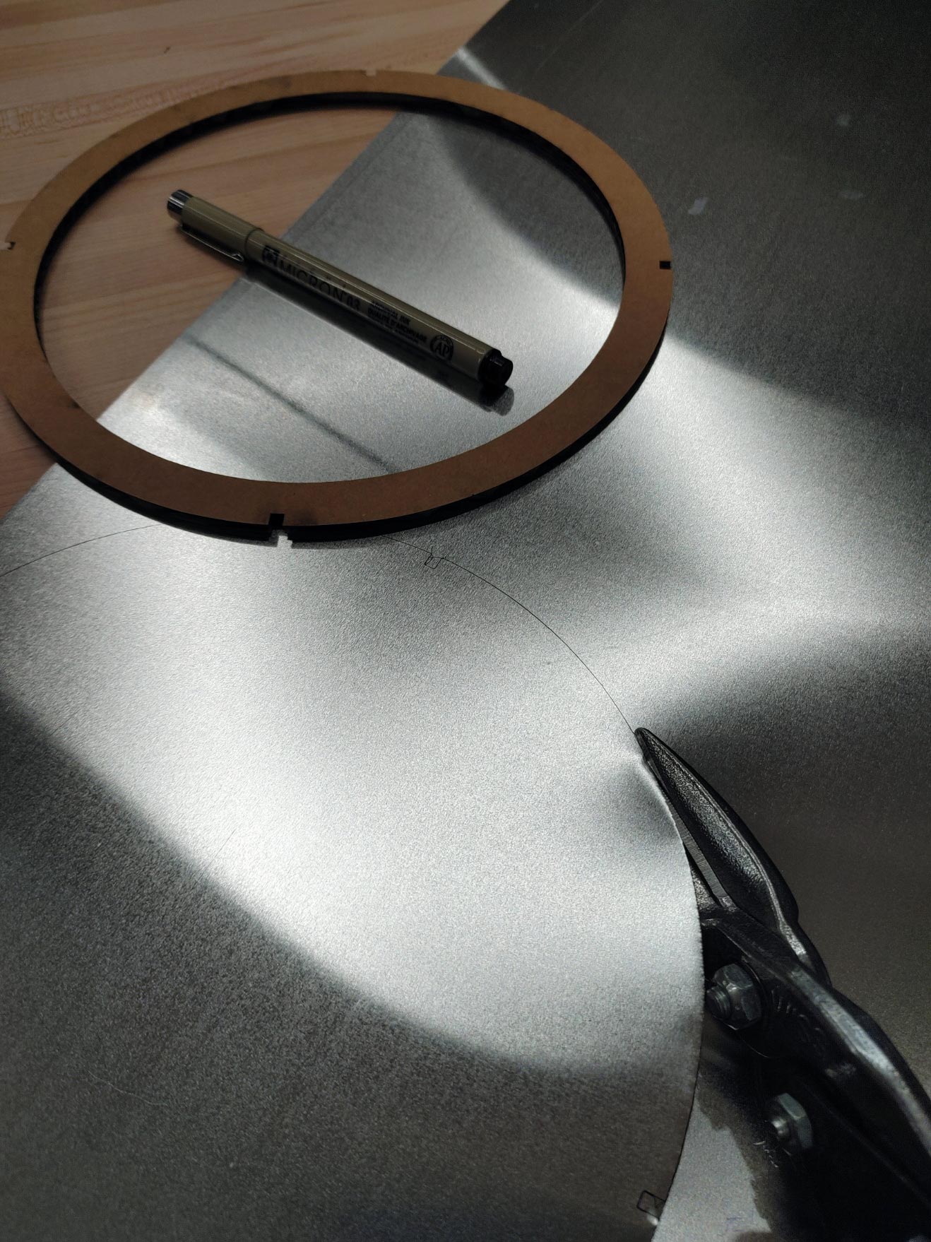
Here is the template I used, though I ended up skipping the grooves in favor of a nail gun. [ Download ]
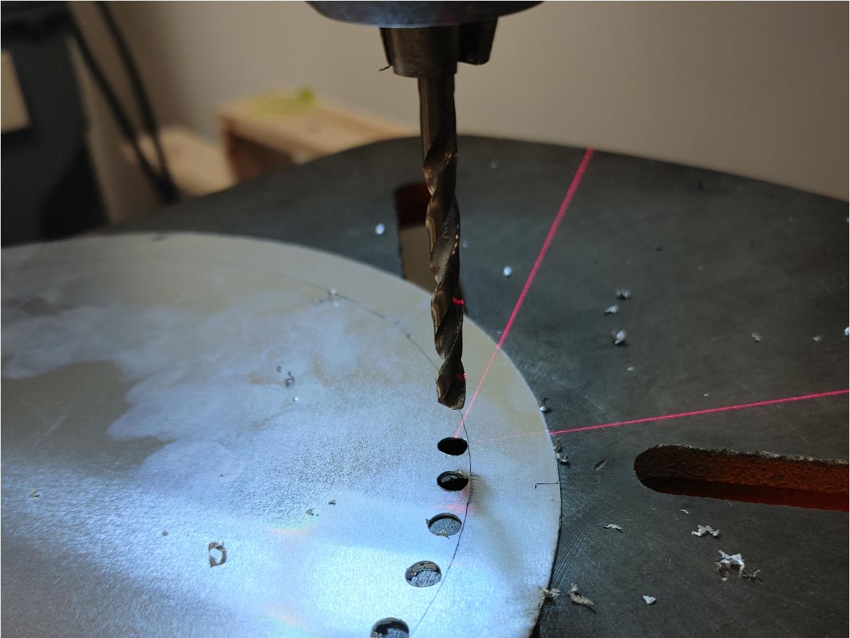
To cut the inside line of the rings, I used a drill press to make holes tangent to the inside line, then cut between the holes to take out the middle, and cleaned up the edge with the metal scissors.
To attach the slip ring to the channel of the wheel, I used a nail gun on the lowest power setting. Unfortunately, even the lowest power setting punched all the way through the slip ring in places, but it worked well enough to keep the ring attached to the wood at the very least.
Lathe
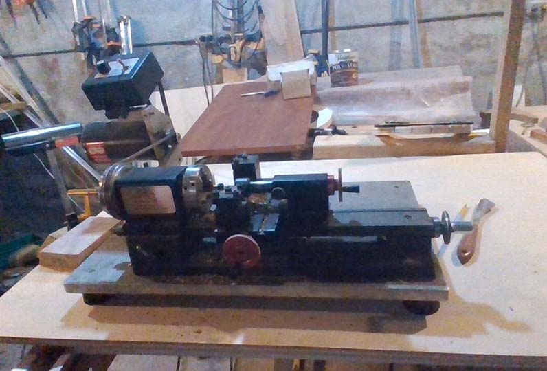
The other part needed to maintain contact with the slip rings are spring loaded pins. I used fusion to create an axel and a pin that could be made on a lathe. I used a soft brass alloy and a small manual lathe to turn the parts. I used a couple different cutting bits to shave the brass rods down to the correct diameter, and I used center alignment bits, and drill bits to make holes on the inside of the axel and the pin.
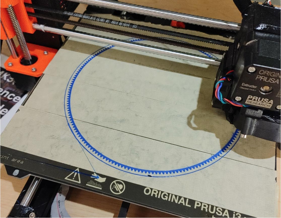
3D printing
I 3D printed all parts of the base. The base is made up of 4 support legs, the base, an LCD cover, a connection piece that holds the tubing, a couple of motor mounts, and 4 wheels for holding the larger wheel. The parts of the base are held together with 3mm bolts. I printed the bear track of the wheel out of flexible TPU filament, so that it would be easier to fit it into place with friction, and so it wouldn’t deform while printing due to cooling. If you want to print the parts yourself, you can open the model in Fusion and export the parts to whatever slicer you use.
PCB board
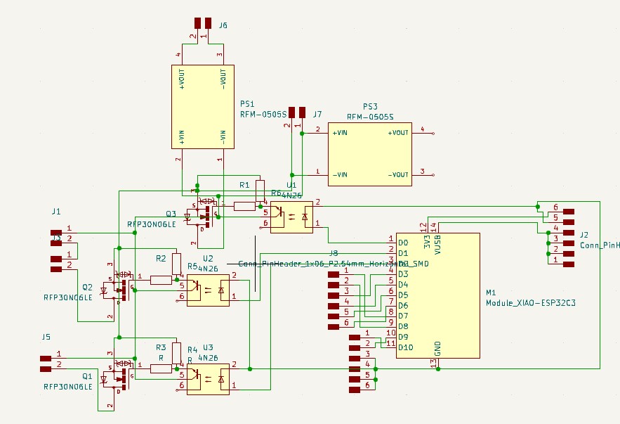
I designed a custom PCB board to control all of the different inputs and outputs of the system. It uses optoisolators, and transistors to switch power to the LED strip, the motors, and the pump. I used Kicad, Adobe Illustrator, and mods to create the toolpaths for the board.
Here is a file with all the SVGs and toolpaths for the board: [ Download ]
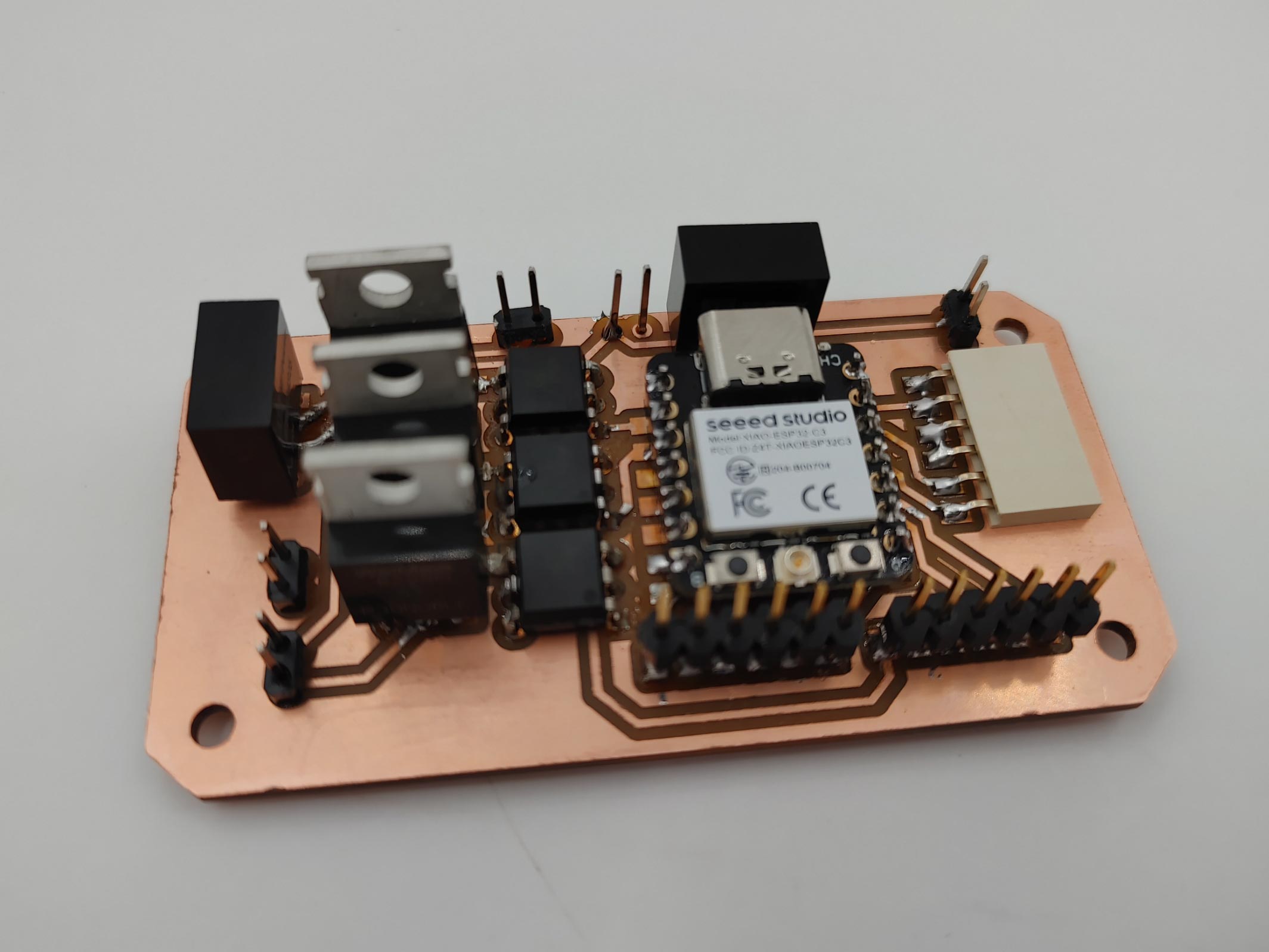
The opto-isolators allow the microcontroller to switch power to the components without the circuit being directly connected. The mosfet transistors allow switching much higher current than the optoisolators, so the optoisolators are used to switch the mosfet transistors on and off. In the schematic editor of Kicad, I needed to find footprints for a few of components in my design. I downloaded them from snapeda.com.
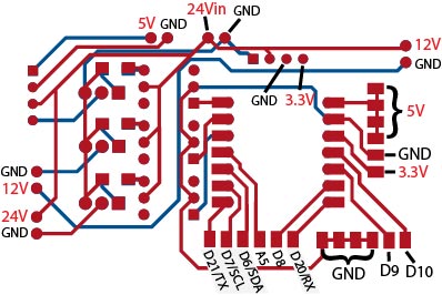
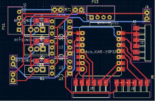
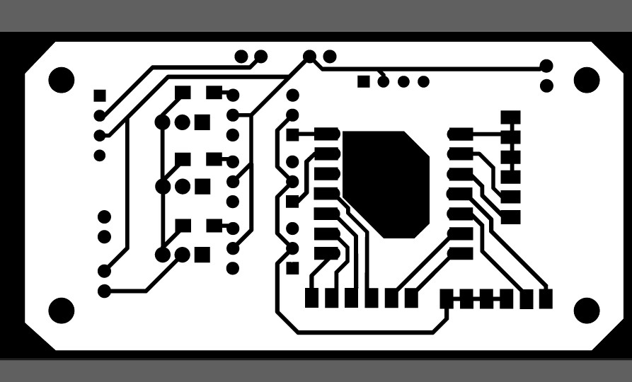
In the PCB editor of Kicad, and arranged all of the parts in my design to be compact, and have ports that would be in convenient locations for plugging the components in. I decided to make it a double sided board to make it more compact.
In Illustrator I made an outline for the board including a hole in the bottom to solder wires to the power terminals on the bottom of the microcontroller. I made holes in the corner to screw the board into the base. To make the second side of the board, I reflected the traces on the opposite side before exporting them to mods.
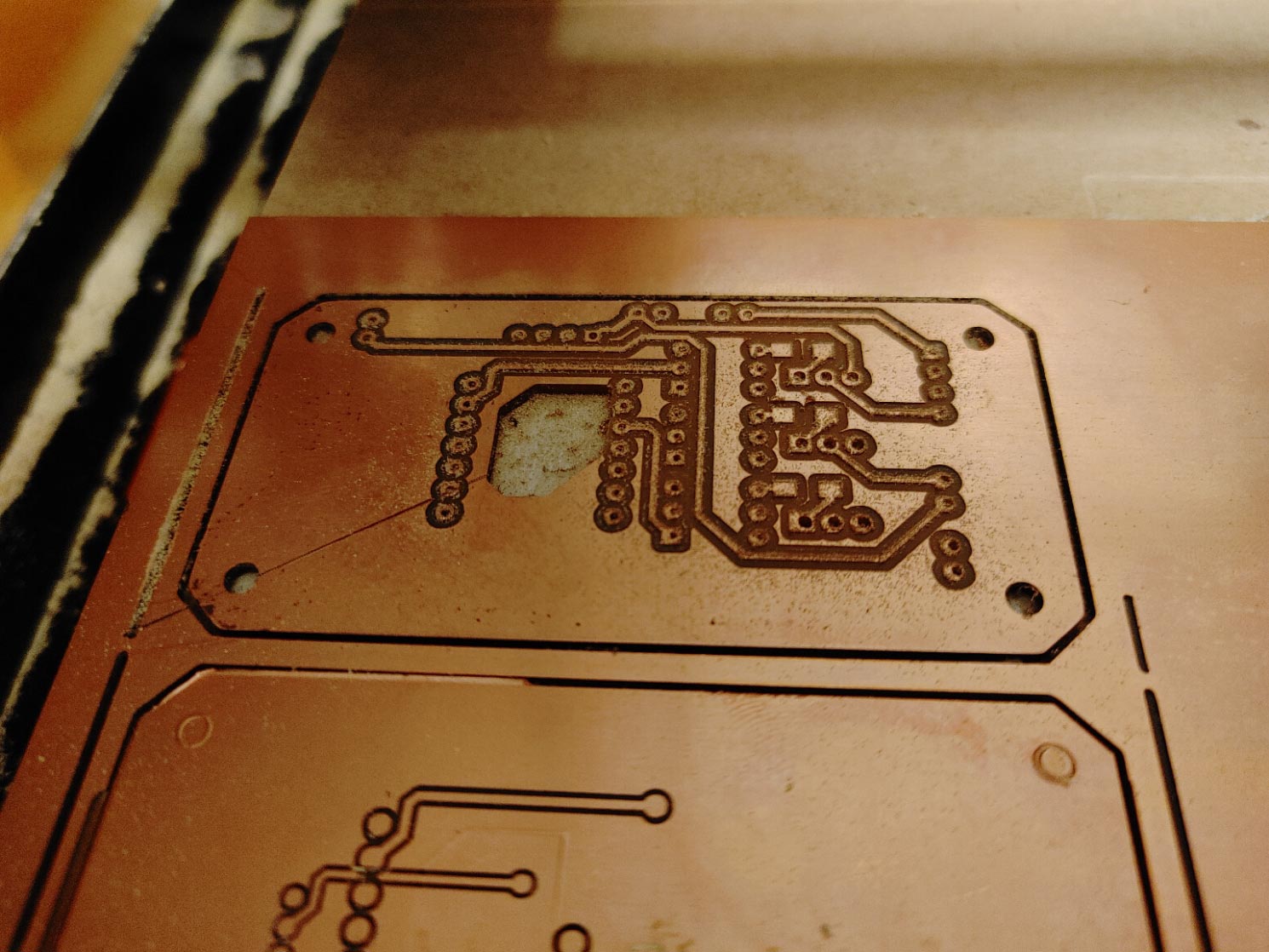
Milling the board went about the same as in week 8, the main difference being that after cutting the board out, I peeled it off of the double sided tape, flipped it over, and carefully placed it back onto the tape in the same place. This was only possible because the shape of the outline of my board is symmetrical. I placed it down off-center by a fraction of a millimeter, but this wasn’t enough to make any functional difference.
Soldering components to my board was a challenge because of the compactness and complexity of the design. I soldered wires to the bottom of the board and connected them to the 24V-3.3V power supply for the microcontroller. I ended up removing the power supply, because I still needed to program the microcontroller, and I placed the power supply blocking the usb-c port. When I don’t need to make any more changes to the code, I can simply solder the power supply back on, and the whole system can run off of the same 24V power supply.
LCD
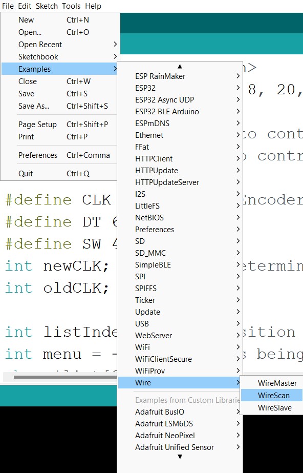
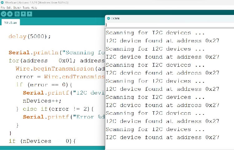
To have enough pins for all of the components, I needed to connect to the LCD using an I2C connection. To do this I soldered an I2C backpack adapter to the back of an LCD screen, and connected it to the SDA and SCL pins on my board. I then opened the example code for finding the I2C address for my device. I was able to use this address to connect to my board using the LiquidCrystal_I2C library.
Code [ download ]
felt
For the felt, I rolled the wheel across the piece of felt and then measured the distance of 1 complete roll to determine the actual circumference of the wheel including the ribbing. I then made a sketch in fusion 360 for both the inside and the outside felt soil coverings.
Wheel assembly
Once I Had the ribs and the wheel halves, I found some small wood blocks for spacing the two halves of the wheel apart. I held them together with superglue, and then clamped them into place.
I used a piece of paper to mark the positions for the screws. I made them offset from the center of the blocks so that they wouldn’t collide inside the wood. This also made room for the holes for the wires to go through.
Drill
I used a drill to make pilot holes for the screws, and then I used an angled bit to create a counter sink so that the heads of the screws wouldn’t stick out too far from the floor of the channel.
Glue
The next step was gluing. I used superglue to secure the ribbing in place, and Tacky glue to secure the felt to the wood. I did the felt one side at a time because gluing the second side would involve pulling the felt over the ribbing and putting negative pressure on the bond.
Slip rings
To maintain electrical contact with the wheel while it’s spinning, it needs slip rings. I bought an aluminum plate at home depot to cut into slip rings. I laser cut a template out of cardboard, and used it to trace the outline of the slip rings onto the aluminum sheet. I then used metal scissors to cut out the rings following the line by hand.
Here is the template I used, though I ended up skipping the grooves in favor of a nail gun. [ Download ]
To cut the inside line of the rings, I used a drill press to make holes tangent to the inside line, then cut between the holes to take out the middle, and cleaned up the edge with the metal scissors.
To attach the slip ring to the channel of the wheel, I used a nail gun on the lowest power setting. Unfortunately, even the lowest power setting punched all the way through the slip ring in places, but it worked well enough to keep the ring attached to the wood at the very least.
Lathe
The other part needed to maintain contact with the slip rings are spring loaded pins. I used fusion to create an axel and a pin that could be made on a lathe. I used a soft brass alloy and a small manual lathe to turn the parts. I used a couple different cutting bits to shave the brass rods down to the correct diameter, and I used center alignment bits, and drill bits to make holes on the inside of the axel and the pin.
3D printing
I 3D printed all parts of the base. The base is made up of 4 support legs, the base, an LCD cover, a connection piece that holds the tubing, a couple of motor mounts, and 4 wheels for holding the larger wheel. The parts of the base are held together with 3mm bolts. I printed the bear track of the wheel out of flexible TPU filament, so that it would be easier to fit it into place with friction, and so it wouldn’t deform while printing due to cooling. If you want to print the parts yourself, you can open the model in Fusion and export the parts to whatever slicer you use.
PCB board
I designed a custom PCB board to control all of the different inputs and outputs of the system. It uses optoisolators, and transistors to switch power to the LED strip, the motors, and the pump. I used Kicad, Adobe Illustrator, and mods to create the toolpaths for the board.
Here is a file with all the SVGs and toolpaths for the board: [ Download ]
The opto-isolators allow the microcontroller to switch power to the components without the circuit being directly connected. The mosfet transistors allow switching much higher current than the optoisolators, so the optoisolators are used to switch the mosfet transistors on and off. In the schematic editor of Kicad, I needed to find footprints for a few of components in my design. I downloaded them from snapeda.com.
In the PCB editor of Kicad, and arranged all of the parts in my design to be compact, and have ports that would be in convenient locations for plugging the components in. I decided to make it a double sided board to make it more compact.
In Illustrator I made an outline for the board including a hole in the bottom to solder wires to the power terminals on the bottom of the microcontroller. I made holes in the corner to screw the board into the base. To make the second side of the board, I reflected the traces on the opposite side before exporting them to mods.
Milling the board went about the same as in week 8, the main difference being that after cutting the board out, I peeled it off of the double sided tape, flipped it over, and carefully placed it back onto the tape in the same place. This was only possible because the shape of the outline of my board is symmetrical. I placed it down off-center by a fraction of a millimeter, but this wasn’t enough to make any functional difference.
Soldering components to my board was a challenge because of the compactness and complexity of the design. I soldered wires to the bottom of the board and connected them to the 24V-3.3V power supply for the microcontroller. I ended up removing the power supply, because I still needed to program the microcontroller, and I placed the power supply blocking the usb-c port. When I don’t need to make any more changes to the code, I can simply solder the power supply back on, and the whole system can run off of the same 24V power supply.
LCD
To have enough pins for all of the components, I needed to connect to the LCD using an I2C connection. To do this I soldered an I2C backpack adapter to the back of an LCD screen, and connected it to the SDA and SCL pins on my board. I then opened the example code for finding the I2C address for my device. I was able to use this address to connect to my board using the LiquidCrystal_I2C library.
Code [ download ]
For the code, I programmed a menu that you could interact with using the REM (button dial). Turning the dial scrolls the menu up or down, pressing the button selects the current item in the menu. While you have an item selected, scrolling allows you to change the settings in the menu. The program uses analog outputs with PWM to switch the motors and lights on and off.
        //Dan collins
//3/27/2023

#include &#ltLiquidCrystal_I2C.h&#rt
LiquidCrystal_I2C lcd(0x23, 16, 2);

int motorPin = 3; //pin to control two motors via transistor
int LEDpin = 4; // pin to control LED strip
int pumpPin = 2; //pin to control two motors via transistor

#define CLK 5 // Rotary Encoder Inputs
#define DT 8
#define SW 20
int newCLK; // used to determine direction of rotation of encoder
int oldCLK;

int listIndex = 1; // position in the list
int menu = -1; // what is being interacted with -1 is main menu, 0-2 are for changing settings
char *list[3] = {"Brightness   ","Pump speed  ","Motor speed  "};
int settings[3] = {5,0,0}; //brightness,wetness,fastness
bool motorState = 0;
bool buttonState = 0;

void setup() {
  lcd.init();
  lcd.clear();
  lcd.backlight();
  pinMode(CLK,INPUT);
  pinMode(DT,INPUT);
  pinMode(SW, INPUT_PULLUP);

  pinMode(motorPin,OUTPUT);
  pinMode(LEDpin,OUTPUT);
}

void loop() {
  newCLK = digitalRead(CLK);
  if(newCLK != oldCLK  && newCLK == 1){ //the first time CLK is HIGH
    if (digitalRead(DT) != 1) { // if DT is aleady HIGH, then it's rotating CCW
      if(menu == -1){
        if(listIndex>0){
          listIndex--;
        }else{listIndex = 2;}
      }else{
        if(settings[menu] > 0){
          settings[menu] -= 1;
        }
      }
    } else {   // Encoder is rotating CW
      if(menu == -1){
        if(listIndex<2){
          listIndex++;
        }else{listIndex = 0;}
      }else{
        if(settings[menu] < 100){
          settings[menu] += 1;
        }
      }
    }
    if(menu == -1){
      for(int i = 0+listIndex; i < 2+listIndex; i++){ // prints out the menu differently depending on listIndex
        if(i==3){ // if it's at the end of the list
          lcd.setCursor(0,1);
          lcd.print(list[0]); // print the one at the begining
          lcd.print(settings[0]);
          lcd.print("%");
          break;
        }
        lcd.setCursor(0,i-listIndex);
        lcd.print(list[i]);
        lcd.print(settings[i]);
        lcd.print("%");
      }
    }else{
      lcd.setCursor(0,0);
      lcd.print(list[menu]); // print the one at the begining
      lcd.print(settings[menu]);
      lcd.print("%");
    }
  }
  analogWrite(motorPin,(settings[2]*(255/100)));
  analogWrite(LEDpin,(settings[0]*(255/100)));
  analogWrite(pumpPin,(settings[1]*(255/100)));
  if(digitalRead(SW) == LOW){ //
    if(!buttonState){
      buttonState=1;
      if(menu == -1){
        menu = listIndex;
      }else{
        menu = -1;
      }
    }
  }else{
    buttonState = 0;
  }
  oldCLK = newCLK;
  delay(1);
}