Illustrator
This week I am continuing with the board I made on week 6. On week 6 I designed a board with Kicad and moved it into illustrator where I created an outline and some text.

This week I learned how to use the mods interface to create a toolpath, and used it to mill out my development board. There was no group collaboration at my Lab this week because Wheaton college was on spring break.
Feed rate is a measure of how quickly the mill cuts through material. It is expressed in units of distance per revolution. Feed rate can affect quality, safety and productivity of the job. The optimal feed rate depends primarily on the bit you are using and the material. If you make it too fast, the bit could break. With the 1/32” and 1/64” bits we use at our lab, a movement speed of 4-8mm/s results in a safe feed rate.
Speed of the mill is the rotation rate of the cutting bit. It is measured in rotations per minute. The mill at my lab has a speed of 8700 rpm.
Plunge rate is the rate at which the bit will cut down into the material from above. The optimal plunge rate depends on the bit being used and the material being cut.
Depth of cut is how far down into the material the bit cuts. This is usually dependent on the design criteria of the part being made. For milling wire traces, this should be a bit deeper than the thickness of the copper coating. For cutting out the outline of a circuit board, you should cut very slightly deeper than material thickness. By slightly deeper, I would recommend you estimate the margin of error of the material thickness and the vertical tolerance of the cnc machine and add those to the material thickness to determine the cutting depth.
The material we are using to fabricate the boards are single sided FR-1 PCB boards. It has a copper layer about 1/1000” thick, which means the traces have to be significantly wider than that to be reliable. The FR-1 boards are 6” by 4”, so boards we make cannot be bigger than that.
We have 1/32” bits for cutting the outlines of the board, and 1/64” bits for milling the traces. This means the wire traces need to be at least 1/64” apart in the design so they can be milled properly.
There are many different types of bits that you may want to use for various applications of a milling machine. Below I have listed a few of the most common and versatile examples.

This is a downcut end mill bit. It is useful for milling into the surface of a board. This is a common and versatile bit.

This is an upcut end mill. The difference is in the direction of the flutes. The upcut forces the material upward, which can result in a rougher top surface. They are also faster, because they pull the material out of the way more efficiently.
There are also other shapes for various applications. Ball nose bits are frequently used for milling out 3 dimensional curved shapes. V shaped bits are often used for engraving text or symbols into surfaces, as you can vary the width of the cut by varying the depth.

This image was taken from this site.
This week I am continuing with the board I made on week 6. On week 6 I designed a board with Kicad and moved it into illustrator where I created an outline and some text.
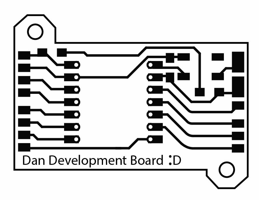
To prepare my design for fabrication, I separated the design into 3 layers; the wire traces, the outline, and the holes.

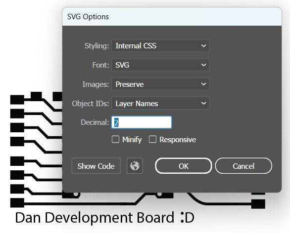
I exported each of the layers as SVGs. Then moved them to mods.
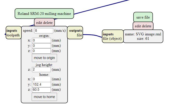
To make the toolpaths, I used [ right click , server programs , SRM-20 (PCB svg) ] to open the toolpath creation algorithm. After that I replaced the websocket module with a save module. You can add one via [ right click , module , open server module , file (save) ] You should also set the x y z coordinates of the origin to be 0,0,0. The speed can go up to 10 with the mill I used.

For the traces toolpath I imported the svg, then inverted it so that the background would be black and the traces white. Next I selected the traces (1/64) setting and hit calculate to generate the rml file.
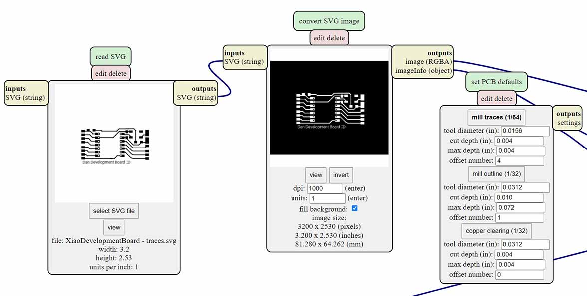
I did a similar process for the outline and the holes. The differences being that I didn’t invert them, and I had to make the holes bigger in order for the mods program to register them. Both the holes and the outline use the outline (1/32) setting.
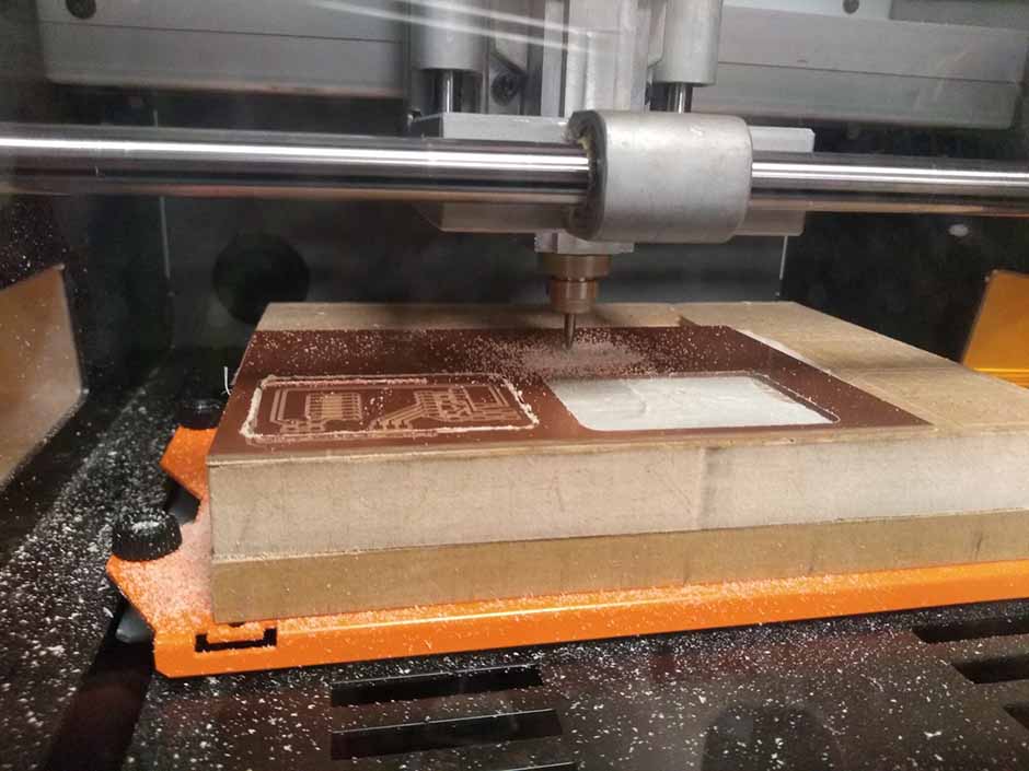
With all of the .rml files created I moved them to the computer connected to the milling machine and opened them in VPanel for SRM-20. I loaded a 1/64 inch bit into the mill and tightened it. Then I lowered the bit to slightly above the plate and loosened it to let it fall onto the plate. Next I lowered the router to give it more grip on the bit and tightened the bit again. At this point I put a small amount of pressure on the plate, then hit the z-zero button. Next I jogged the z up again, then moved the bit to a good x/y position and hit the x/y zero button. Finally I hit cut and selected the .rml file for my traces and hit upload to start the milling process.

Between milling the traces and the holes, I vacuumed up some of the debris, switched the bit out for a 1/32 in end mill, and redid the z-zeroing process. It is important not to redo the x/y zeroing process. The outline was the same as the holes, so no steps were necessary between these two operations.
I ran into an alignment problem when milling the holes and the outline. I’m not sure of the cause, but I found that re-exporting the svg files and importing them into mods fixed the problems.
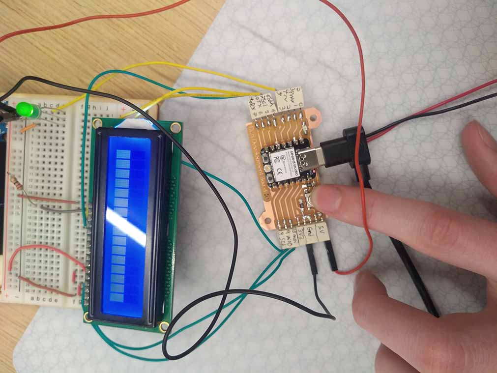
I started the soldering job with the through-hole pins. I moved the plastic connecting piece to the end of the pins to give the most space above the board to attach the Xiao board. In retrospect I would recommend doing through-hole pins last, because it meant the board was balancing on the bottom of the pins for the rest of the soldering. I used rosin core lead free wire solder, and set the soldering iron to 700 degrees fahrenheit. Holding the tip to the copper for 5-10 seconds was enough to get the solder to adhere pretty well.
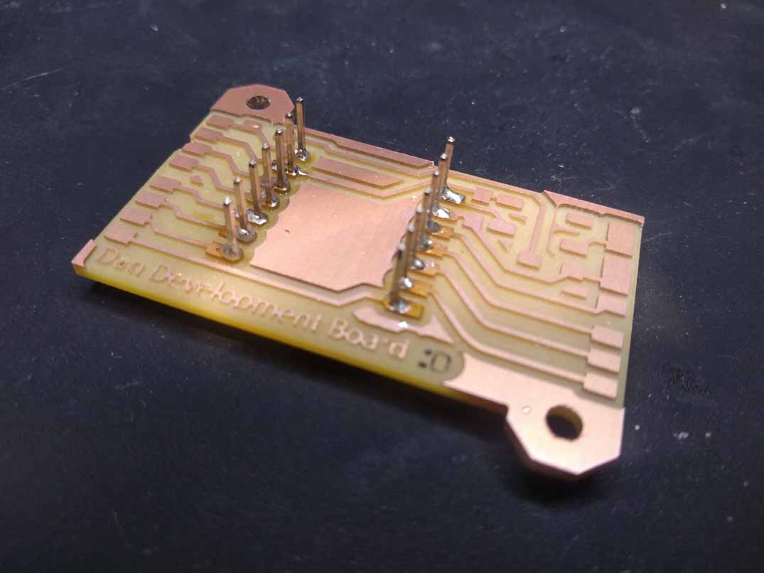
Next I attached the pin connections. I cut these connectors off of sets of 6 so they all have a rough side. I had to prop them up while soldering because of the through hole pins. I found that getting one pin stuck to the board with a little bit of solder, then keeping that solder melted while moving the component into place, is much easier than trying to keep it perfectly aligned while soldering. In retrospect, the pin connections aren't very well protected in my design, but it isn't a big problem for my purposes.

Next up are the smaller surface mount components: the button, the LED, and the resistors. I found that the resistors liked to stick up when you solder one of the sides. This is not a huge problem, as I mentioned above, once you have it stuck to the board with solder, you can hold the resistor with tweezers and melt the solder to position it. I tested the led with a multimeter to determine which side was ground. It turned out to be the green line on the ground side.
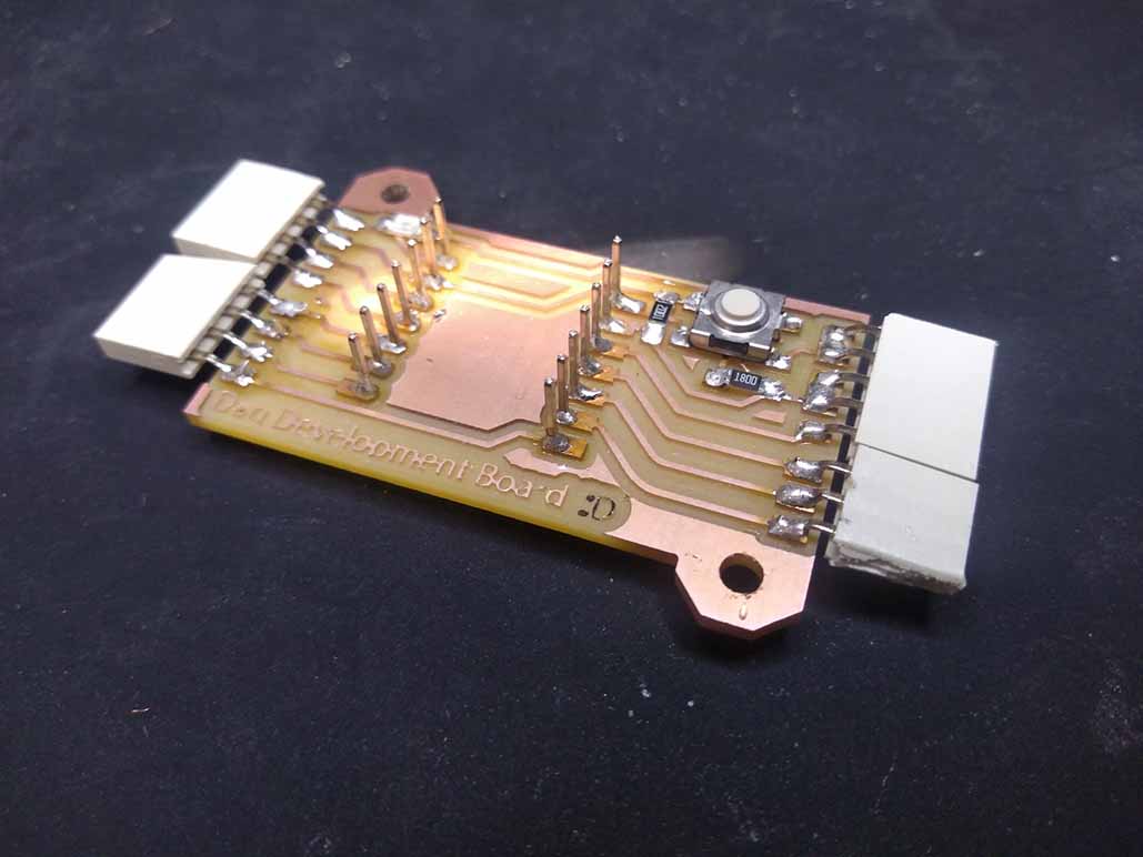
I wanted to be able to power the board with a battery, so I soldered wires to the battery pads on the bottom of the Xiao board.
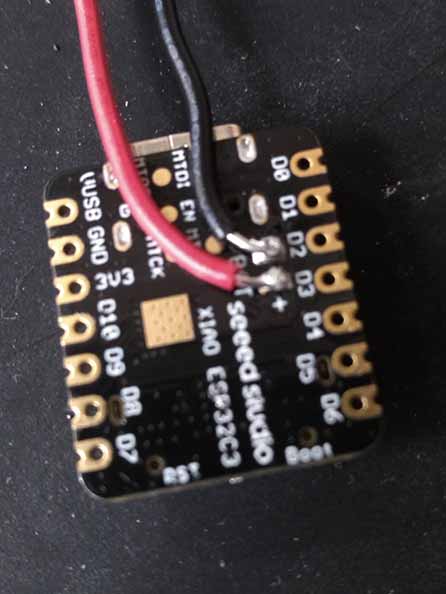
Finally I slotted the Xiao onto the pins and soldered it into place. The wires kept it suspended a safe distance above the copper traces.
I tested the connections with a multimeter using the setting that makes a sound whenever the resistance drops below a certain threshold. I also tested the button and the led with a simple code. The Led lights up whenever the button is pressed.
here is the code