7. Computer Controlled Machining
Our assignments this week are all about using the CNC machine to do computer controlled machining to build furniture scale pieces.
Group Assignment
Our group assignment this week was to complete our labs safety training. We also needed to test our runout, alignment, fixturing, speeds, feeds, materials, and toolpaths for our machine, which is a CNC router and plasma cutter.
The link to our full group work page can be found here.
The majority of our group assignment will be housed at the top of Andy Bruening's week 7 page.
Group Work Summary
Safety at PAST Innovation Lab
Some of our basic rules are as follows: general shop safety (no running, horesplay, etc.), anyone within a certain radius of a machine must be wearing eye protection, and anyone under 18 must have permission and a chaperone in the room while using any equiptment. It is recommended that people with long hair should secure it back before using a machine. Puffy/big sleeves should be secured. No open toed shoes when working with materials. Because I am an adult staff member here, I do not need supervision, but I did have one of my colleagues with me the first time I used the machine, just in case something went wrong. It is always a good idea to have another person with you when you are working with heavy materials or hazardous machinery. In the PDF below, you will find more of the nitty gritty details.
PAST Innovation Lab MakerSpace Safety DocumentThis attachment goes over the rules for operating and maintaining a safe workshop and makerspace.
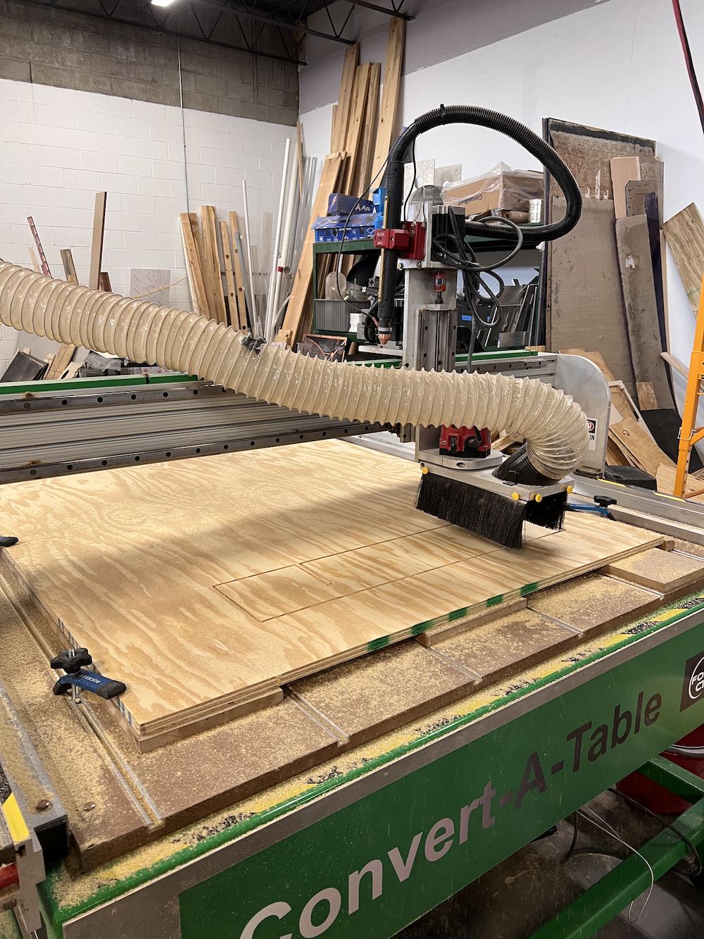
The CNC machine we have is the Forest CNC Convert-A-Table. It has a 96x48" working space. This machine specifically can be used as a CNC Plasma cutter or a CNC router.
To use the plasma cutting feature, the spoil board gets removed, and the bed is filled with water. The plasma feature is best when you need to cut metal. Once you finish, the water is drained and the spoil board is placed back on.
The router feature is super easy to use with basic woods and plastics (polycarbonate). The router can cut through relatively softer materials, but will have a very hard time with metals, especially hard ones.
The baic workflow can be seen in my individual assignment below, but basically, we start with a part file in Onshape, or a similar modeling software such as Solidworks or Fusion 360. You can also create a 2D cut design file with paths in Vectric's Cut2DPro.
Once you have your design file (DXF is preferred), we will import that into Cut2D Pro. This is where you will create the toolpaths for your machine to follow. In Cut2DPro, you will follow these steps to create the toolpath:
- Import files into Cut 2D Pro (.dxf files are preferred).
- Set Material Size: Ensure that the overall material size matches or exceeds the size of the finished product. You can do this in the Job Setup section.
- Set X, Y and Z zero for material: Manually move the router head to the X and Y the respective edges of your material alining with the tip of the bit. To set Z zero manually move the router head to the middle of your material and use the Z-zero touch pad.
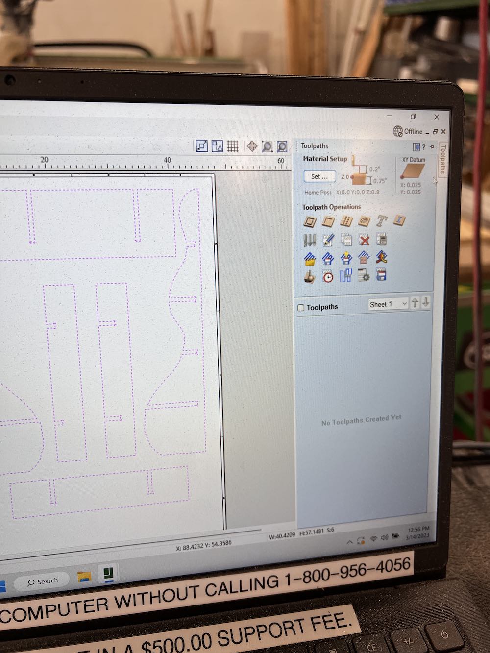
- Select Vectors: Start by selecting the vectors you'll be using for machining onto appropriate layers (if applicable).
- Choose Tool path Strategy: Work through the tool path strategy icons (pocket cut, profile cut, engrave or drill) you wish to use to machine the job. This will calculate all the required tool paths.
- Preview Tool paths: After creating each tool path or at the end of calculating them all, preview the tool paths in the 3D view. This step is important to verify the position, detail, and look of the overall finished part.
- Save Tool paths: Choose the appropriate Post-processor. In our case we are using the ForestCNC router.
Other Important CNC Terms and Information
Runout: Runout is inaccuracy of a tool that causes it to spin slightly off of its perfect axis. If this is minor, it increases the width of the cut kerf. Sever runout can also cause vibration, tool damage, and could cause your tool to break. It is ideal that your runout be as close to zero as possible, if not you may struggle with inaccuracies of your project results. To measure this, a small square block and small squae hole (of the same size) can be cut out. The presence of runout will not produce accurate sizes for the hole and the block you cut out. The size difference when you place the block into the square hole will be your runout. From our previous cuts, there was no drastic runout that prevented our joints or blocks from fitting.
Speeds and Feeds: I used the default speeds and feeds. For our 1/4" end mill, we cut at 50 inches per minute, plunge rate of 17 inches/min, at a spindle speed of 24,000 RPM. The pass depth is 0.26 inches.
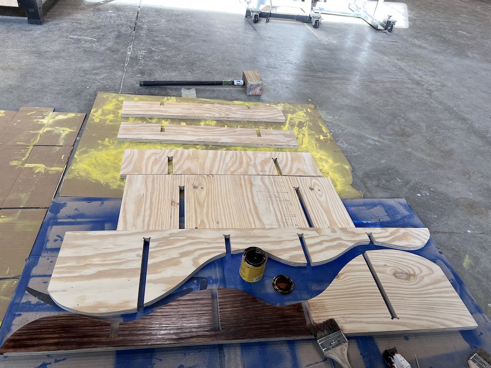
Materials: We used one material for the group and individual assignments. We each got one large sheet of 3/4" sanded plywood.
Tabs: Tabs are useful for keeping material level and attached to the main portion of the material board, basically preveting them from falling underneath the set Z level of the machine. Tabs are small sections of material that remains partially uncut.
Fixturing: Fixturing is the way the material is secured to the bed/spoil board of the machine. We use clips on the sides and corners of the material to ensure it all stays down and level with the Z axis limits.
Alignment: Alignment is the levelness and straightness of the spoil board.
Helpful Research, Downloads, and Equiptment
For research, I did a quick google search for inspiration of what I should make using the CNC machine on a large-scale. I wanted the design to be minimal in parts, easy to assemble, and require no other fixtures such as screws, glue, etc. I found inspiration from this youtube video. I also found this Instructables link very helpful. These designs helped e figure out how I should design my shelves for my bookshelf. I wanted this bookshelf to be simple, and have a fluid but firm structure to it, hence the curved side pieces and the square ended shelves. I started working on my design in Onshape, since I have become more familiar with it as my CAD/3D modeling tool.
Individual Assignment
Our assignment this week was: Make (design+mill+assemble) something big
Our learning outcomes for the week were: Demonstrate 2D design development for CNC production, and Describe workflows for CNC production
Onshape
The design I wanted was influenced most by the Youtube video I linked above in my research. When starting in Onshape, I began with my side pieces that will support the shelves. I wanted the curvy look to it, but knew it needed to be heavier on the bottom so it would be balanced and not top heavy.
I made this by creating two lines for the back edge that will go up against the wall and the edge that will go against the bottom. I made this a right angle so it would stand straight and stay vertical. I then used the spline tool in Onshape to create the curved edge in the front. I planned to have one concave or convex curve per area I wanted a shelf, and I wanted them to be relatively the same distance apart. Once I placed the spline, I adjusted it to my liking.
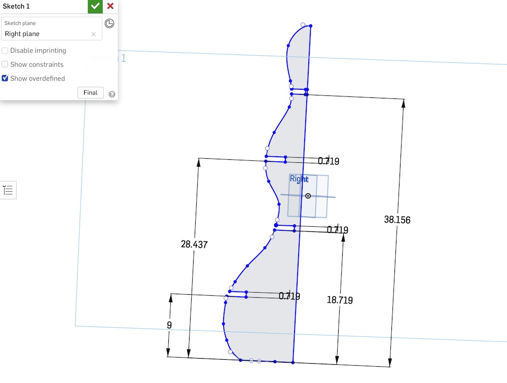
To make the slots where my shelves will go that you see above, I used the corner rectangle tool. I placed the rectangles in roughly the place I wanted the shelves then used the dimension tool to make the width the same as what my plywood is, which is 23/32 inches. I lined the rectangles up so they are overlapping over the edge of the front curved line. I went in next with the trim tool and trimmed out the overlap so the rectangles now have three straight edges and one open end that is attached and open to the front.
I next used the extrude tool to make my sketch 3 dimensional. I set the thickness to 23/32 inches to account for the thickness of the plywood I am using. After I finished the sketch I selected then copied all sketch entities. To make distance between my side pieces, I had to create a new plane. I did this with the plane tool, selected the right side plane, and offset it by 12 inches. This is the distance I wanted my side supports to be apart from each other. Once I had the new plane, I started a sketch on it and pasted my sketch 1 entities and lined them up to be even with each other. To finish the sides, I extruded my sketches and set the thickness equal to that of my plywood, 23/32 inches.
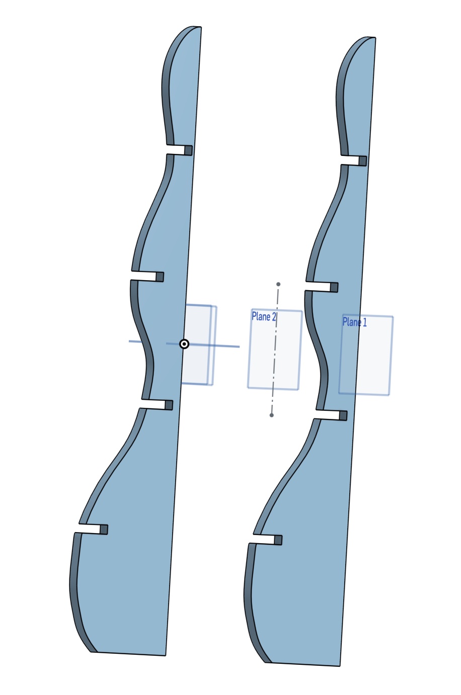
To start designing my shelves, I needed to first create new planes at the base of each of my shelf cutouts so I knew they would align properly and I could get an accurate 3D model of my design. I used the plane tool and offset them by the relative distance they are from the top plane. Once I had this done, I could start a sketch on each plane and design the size and shape of my shelves.
I started the sketch for my first shelf using the corner rectangle tool. I made the dimensions slightly larger than the distance between my side panels so they shelves would protrude from the sides and have more room to fit things on them. In my original idea, I was just going to have the shelves be solid, with no cutouts, but ended up changing that later on.
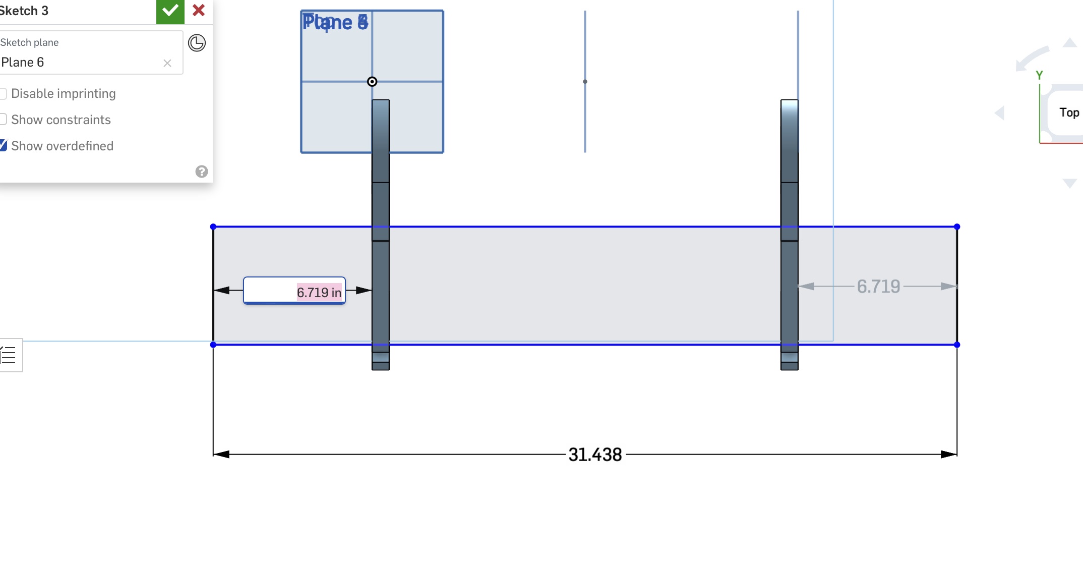
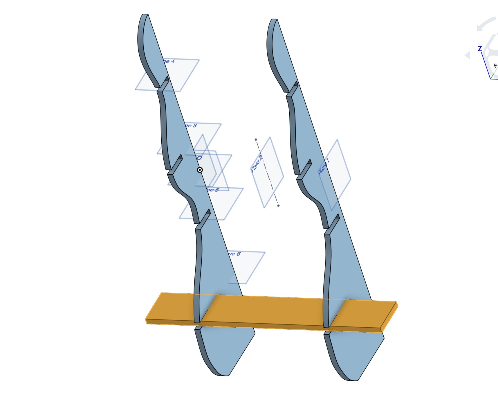
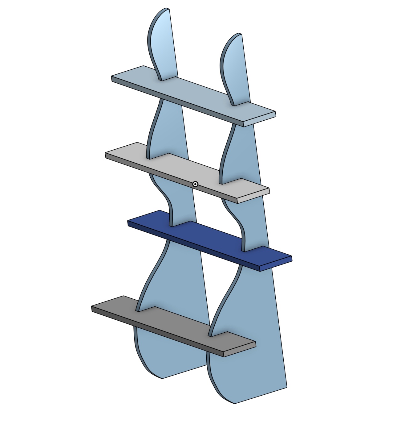
This is the sketch and extrusion of the first shelf I originally designed. I did the same for each of the 4 planes I created to make 4 shelves. I adjusted the shelf depth depending on what height they are, because my side panels are curvy and wider at the bottom. This will give it a better look and a more structurally sound distribution of weight.
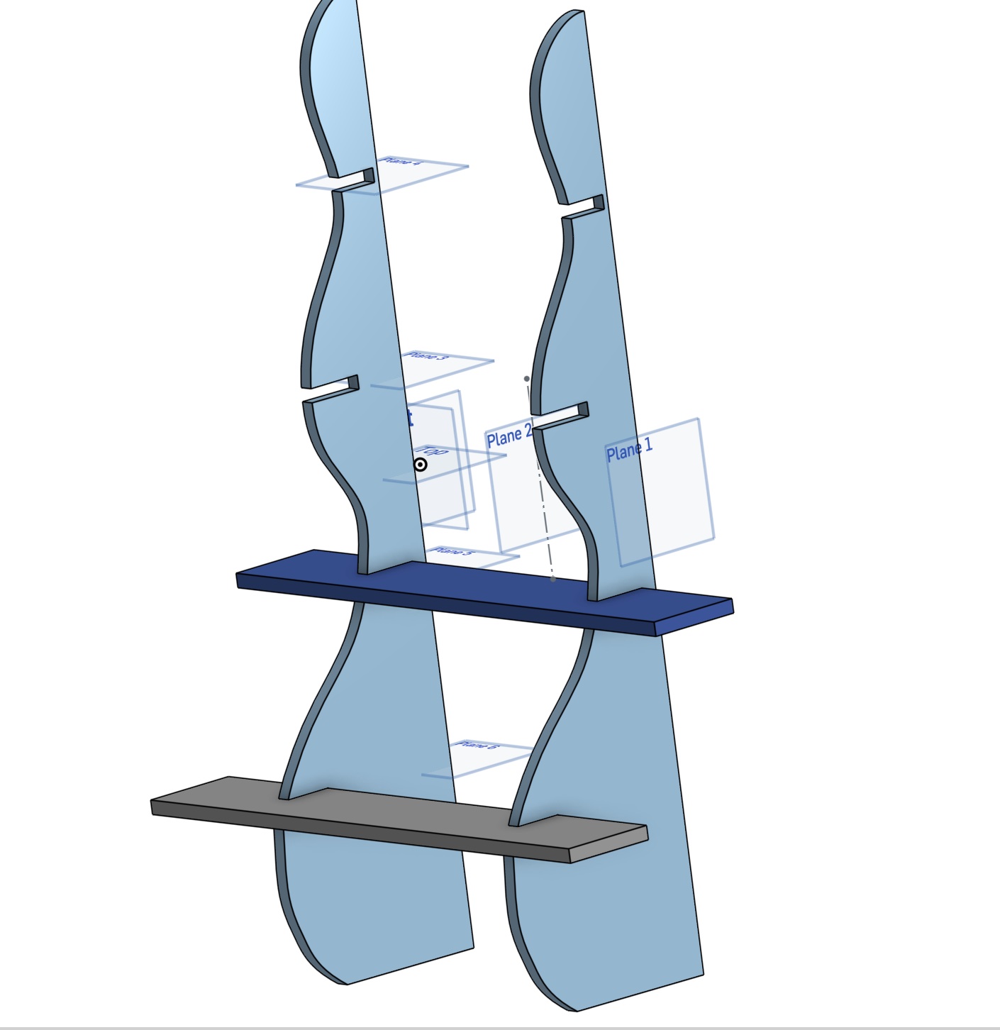
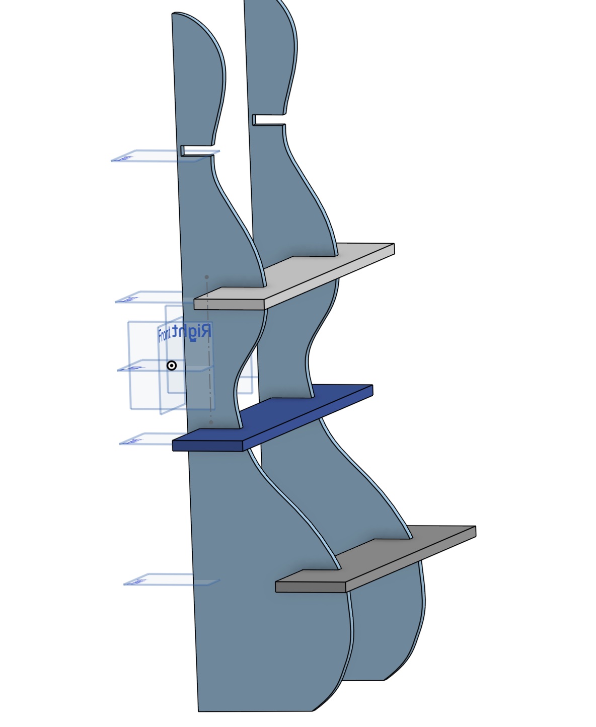
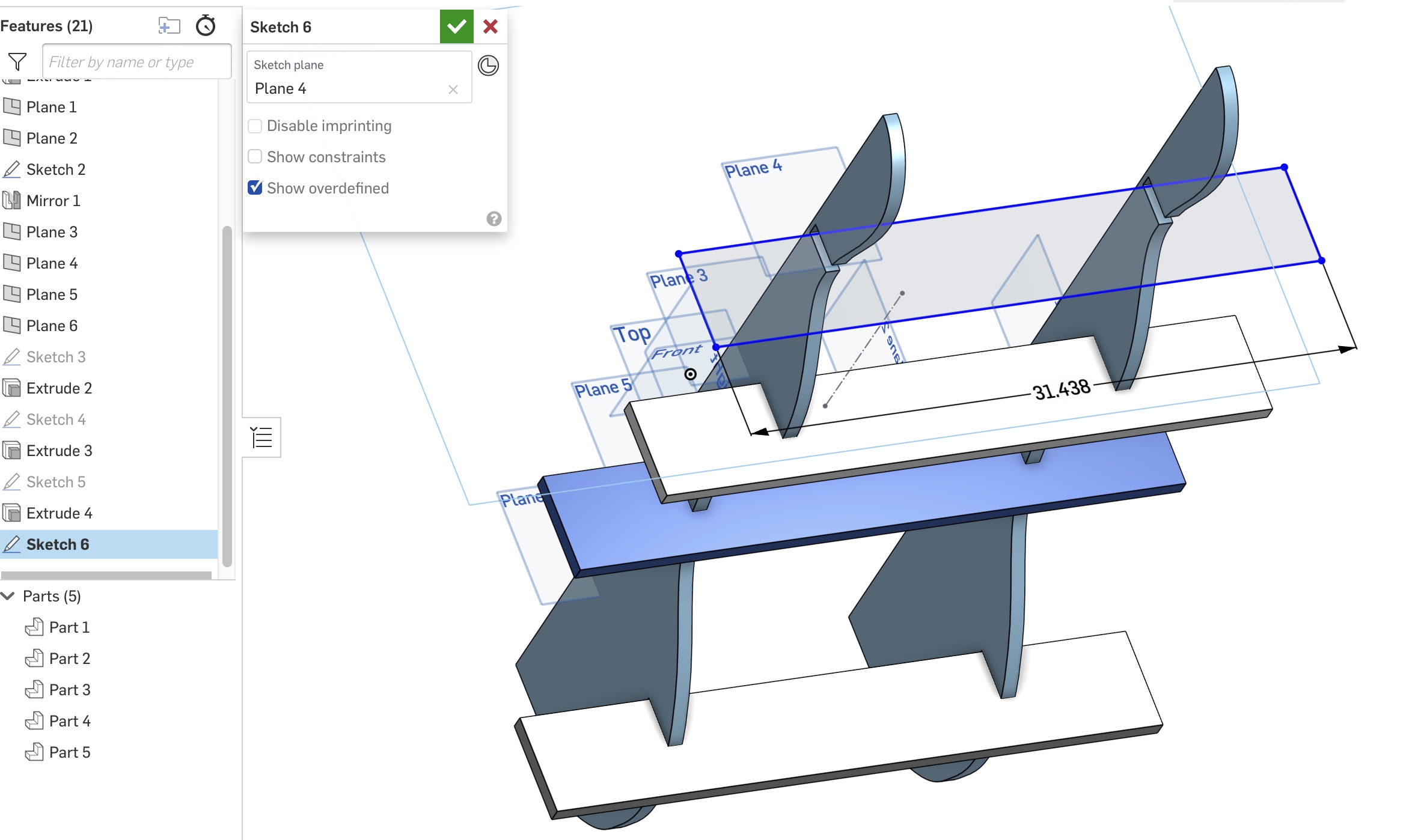
This is what my design originally looked like when I was just using solid rectangles as my shelves. I later realized I should make another groove on my shelves so they can sit deeper on my side panels and may fit together easier. I did this by going into each of my shelf sketches and adding a rectangle where it is attaching to the side. I set the dimensions of the grooves equal to my wood thickness, 23/32 inches, and placed them equally distant from each end. This will keep my symmetry.
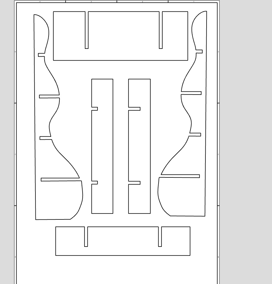
After I added the grooves, I made a drawing in Onshape and adding each of my parts from the parts studio. It will look like the image above. I then needed to export the drawing to a flash drive as a PDF to open it on our computer for our CNC machine.
File Needed for CNC Machine
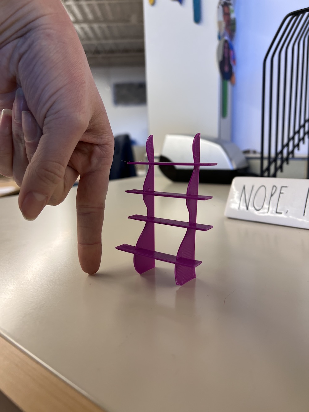
This is a small, very small, model of my bookshelf. I wanted the print to be quick (under half an hour) and needed to make sure the shelves would go into my grooves. I printed and tested this before making the adjustment to my shelves that added two grooves for connection. It worked! I now have a very tiny bookshelf on my desk for tiny trinkets.. Not sure what will even fit on there but it looks cool!
Using the Forest CNC Plasma, Router, and Milling Machine
Now that I have my PDF file ready on my flashdrive, I headed back to our shop to get started editing the pieces and making sure everything is ready to be cut.
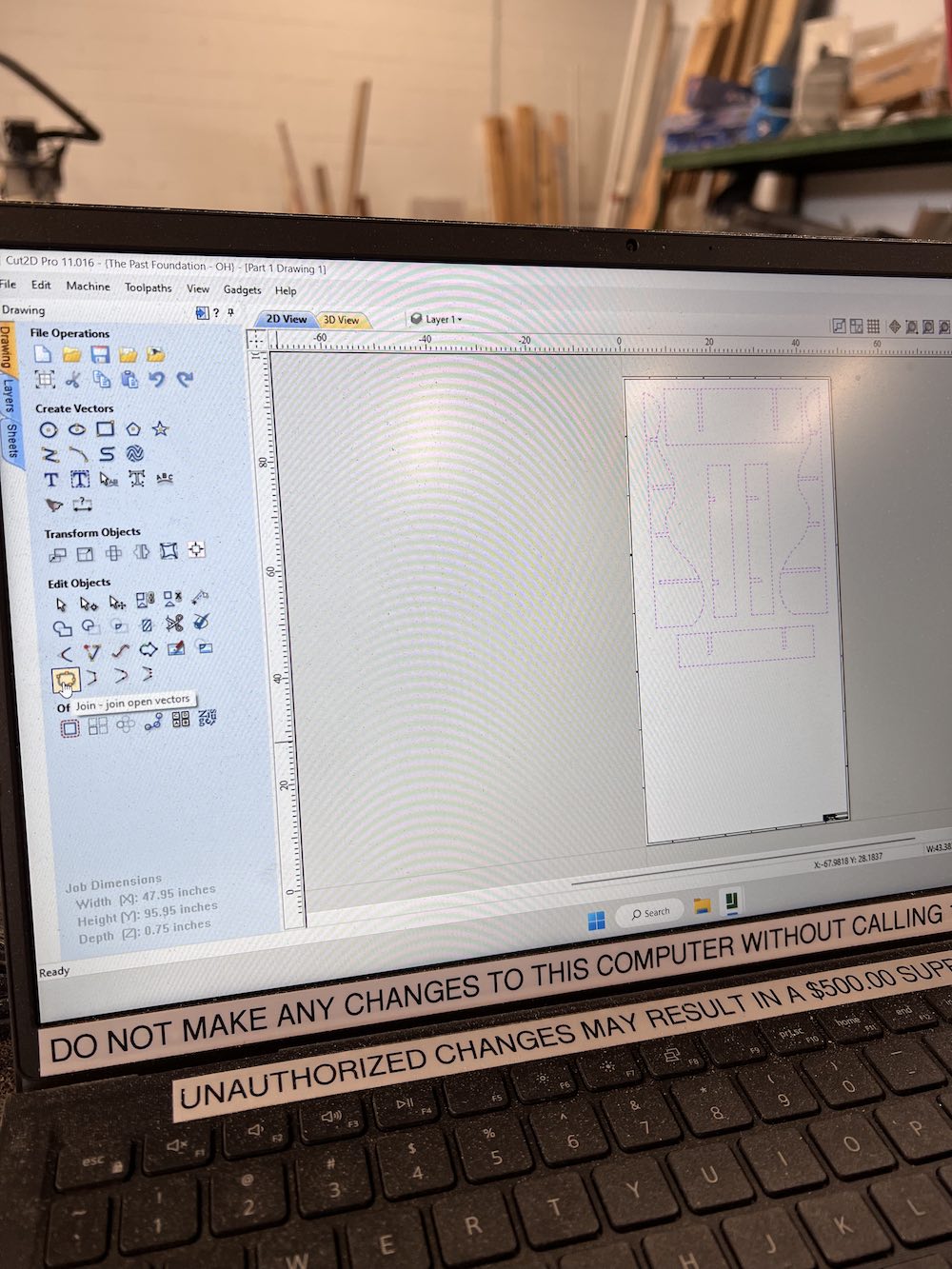
Here, I have opened my file in Cut2D Pro version 11.016 and am getting it ready for cutting. I need to make sure everything in my drawing is joined together and there are no gaps that will be left uncut. I do this with the join tool.
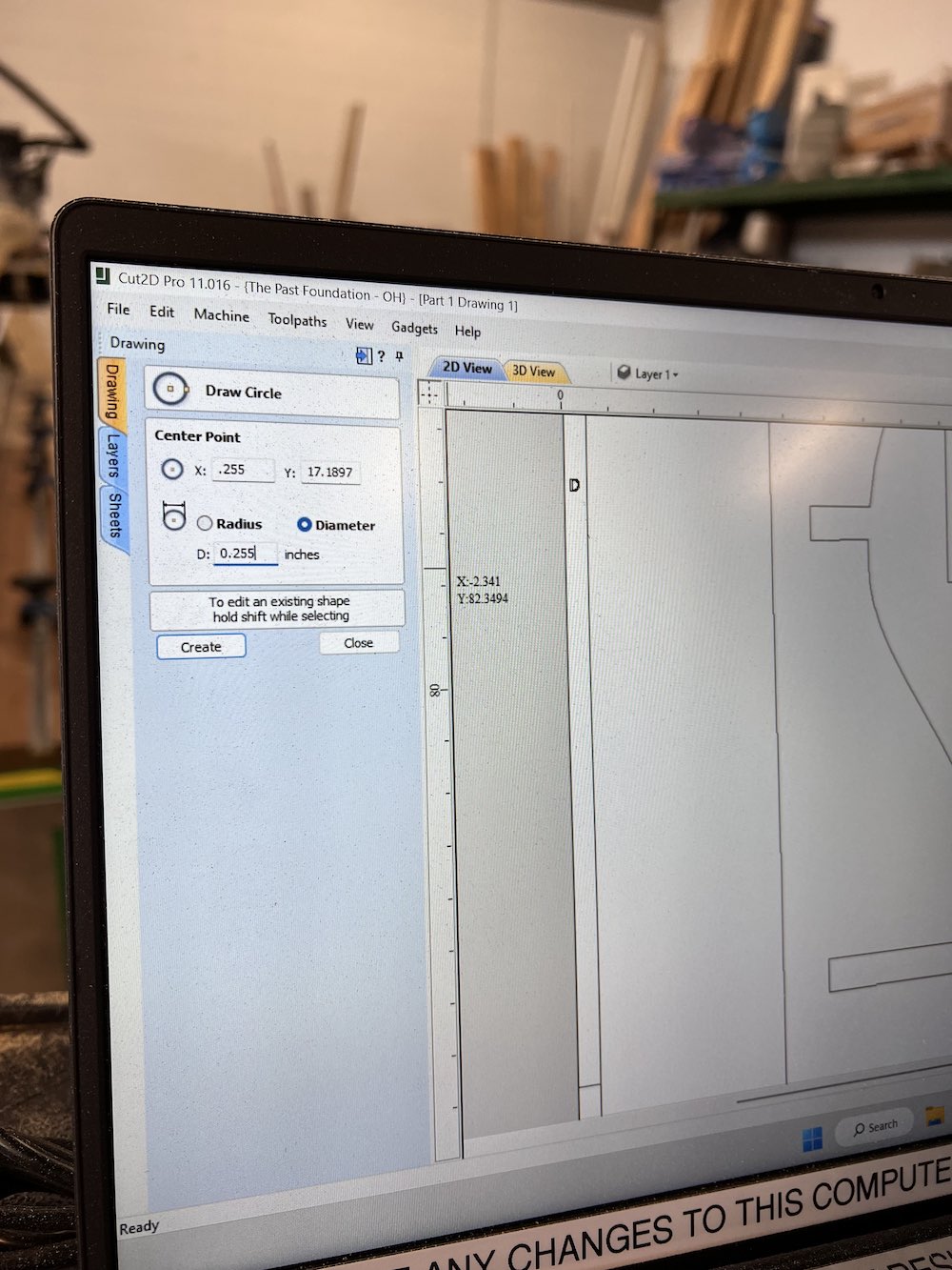
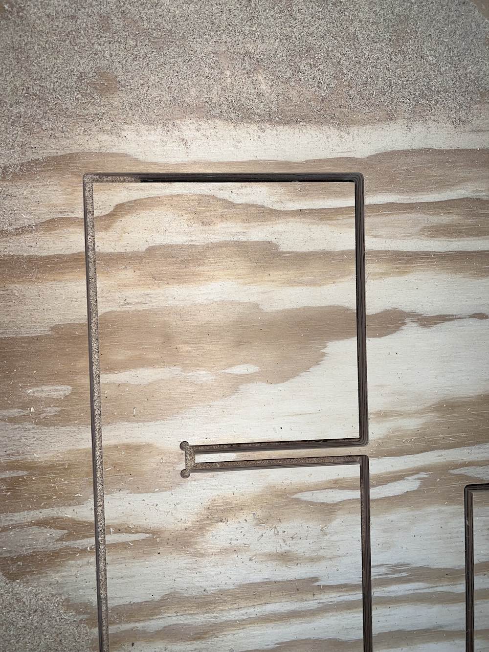
Here, I am adding dogbone cuts to each of my sharp corners I have in the design. Because the CNC mill tool is round and has a 0.25" bit, it will not make 90 degree corners on its own, so I needed to plan for this and make it bigger than the original corner so my shelves would slide fully in place.
To get my CNC mill to cut my pieces out, I need to add a toolpath.
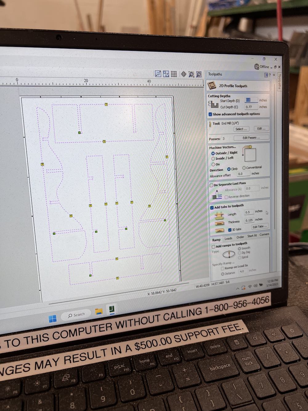
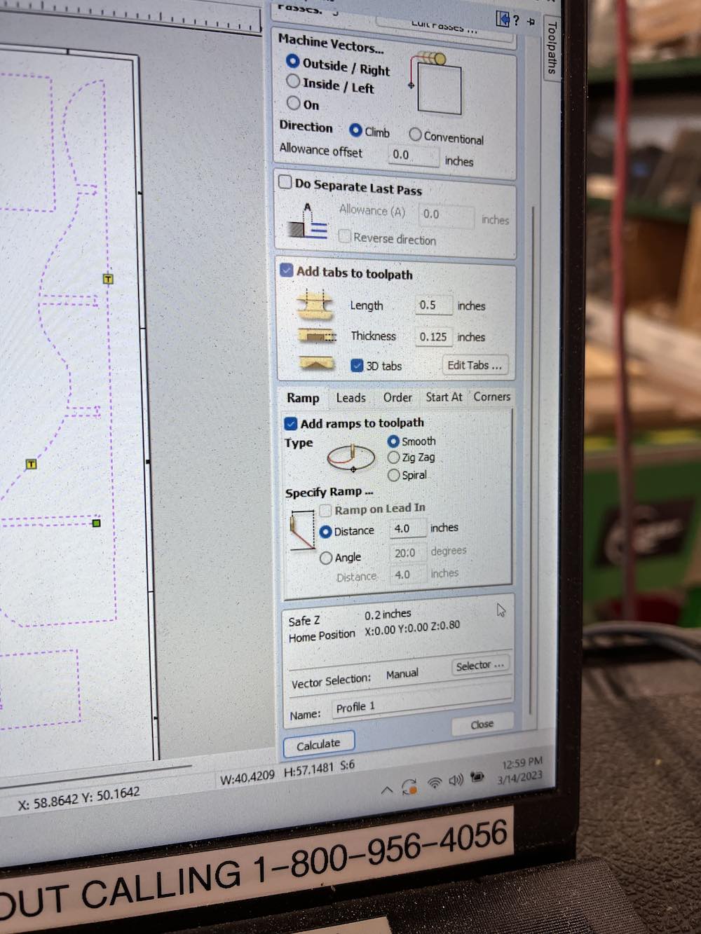
I am adding tabs to my toolpath so when my machine finished cutting a piece, nothing will move or slide or fling around if it gets caught on the routing tool. I also added ramps so there would be smooth transitions between cuts and nothing will abruptly start or stop.
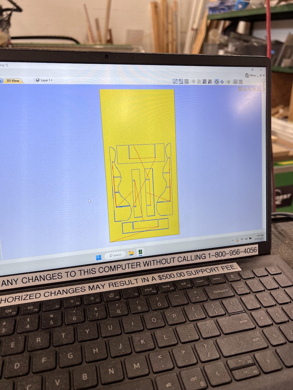
In this image, I have opened the 3D view of my file and it shows what toolpath the machine will take. This tells me also which pieces it is cutting first and the route it will take to complete.
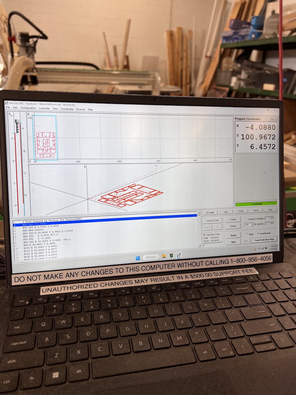
I now exported my file to the Velocity CNC application. This is what the file will look like and this is also where I will adjust the machines zero points, or "home" location. This is where the machine goes when it is time to start or stop cutting. I was able to also see the time it will take to cut the parts out on this machine, adjust the speed, and all other specifics of the router.
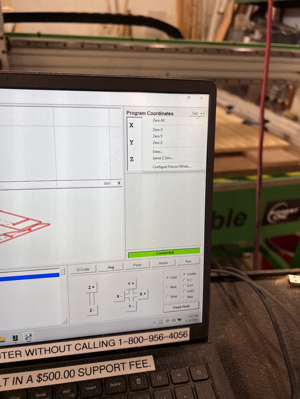
After using the maual moving tool to move my router where I wanted my origin point to be, I clicked Zero X and Zero Y here.
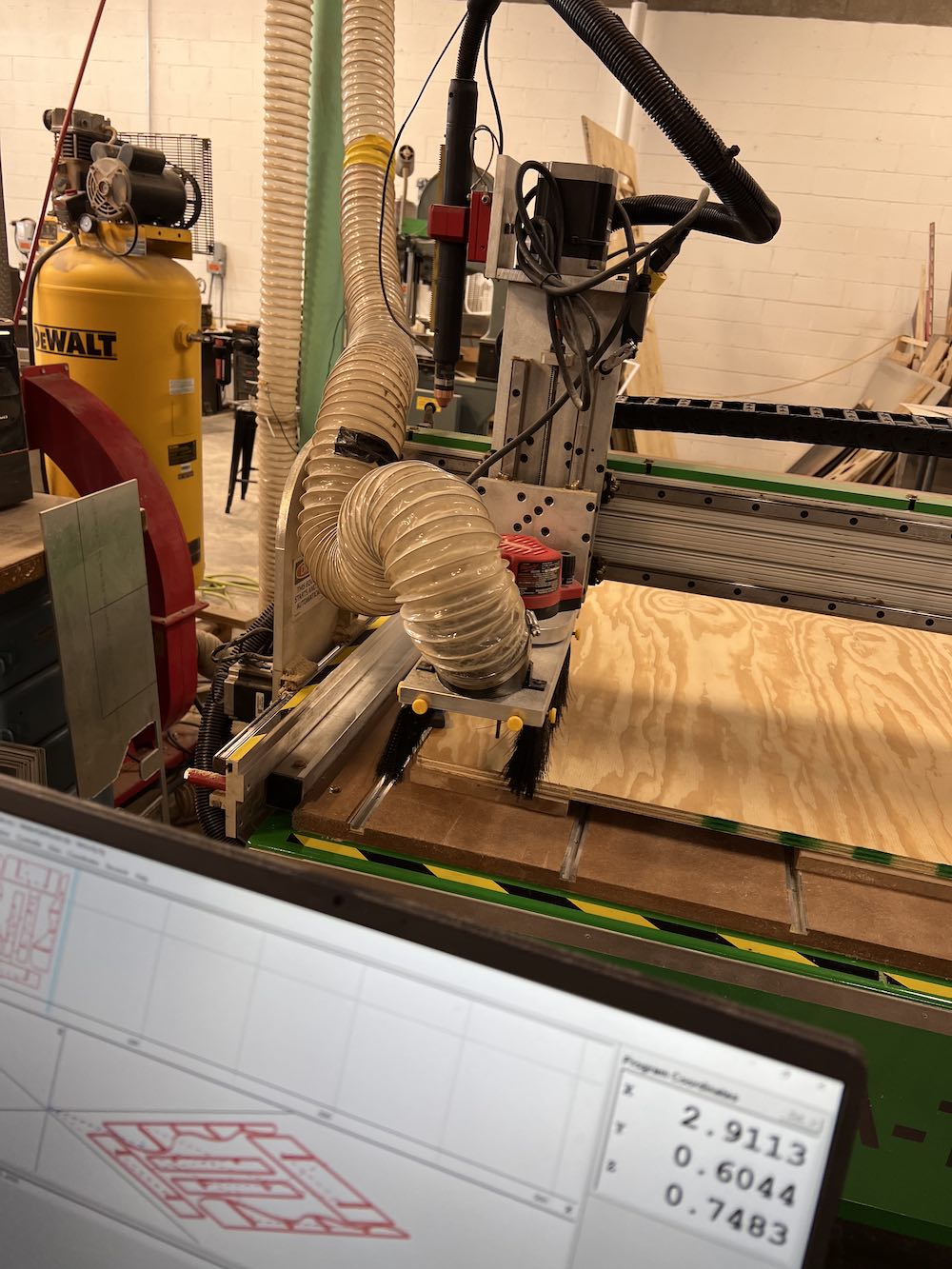
I was told by my colleagues Nikki and Andy that in order to set the Z home/zero location I needed to use this special aluminum block. This will make it so the routing tool does not go too far into our table or my work.
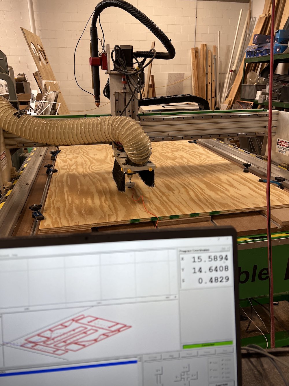
Progress Pictures
Slight Issues
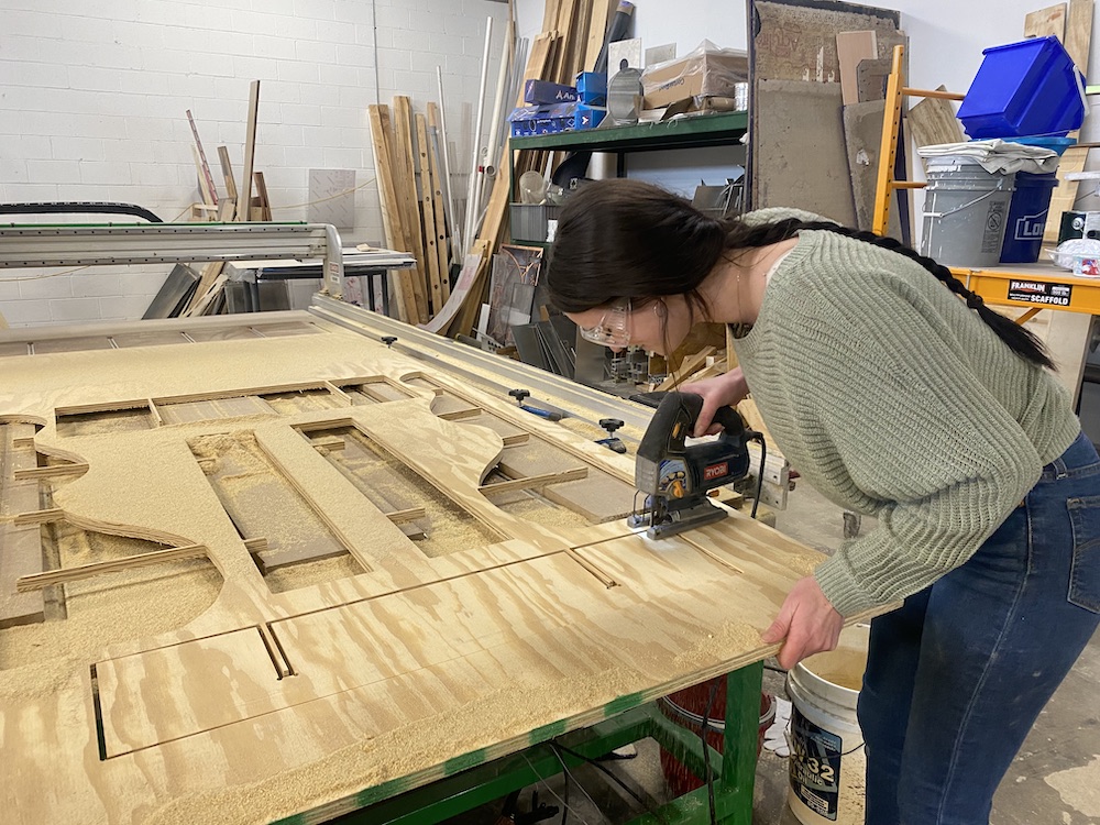
In order for the pieces to be cut through all the way, we needed to slide 3 pieces of equal thickness plywood underneath them. This will prevent our router tool from going into our table underneath and also avoid getting roughed up by the metal slats we have for our clamps. This was one solution to the problem.
<
This is an example of what I mean above. Even though we adjusted the plywood to be higher up, and the cutting depth to be slightly larger than my plywood thickness, some of the parts were not all the way cut through. It was mainly just this one shelf. My guess is the boards are warped and even though we clamped down all the edges, it must not have been fully flush. To finish cutting, I just needed to use a jigsaw to cut the piece out.
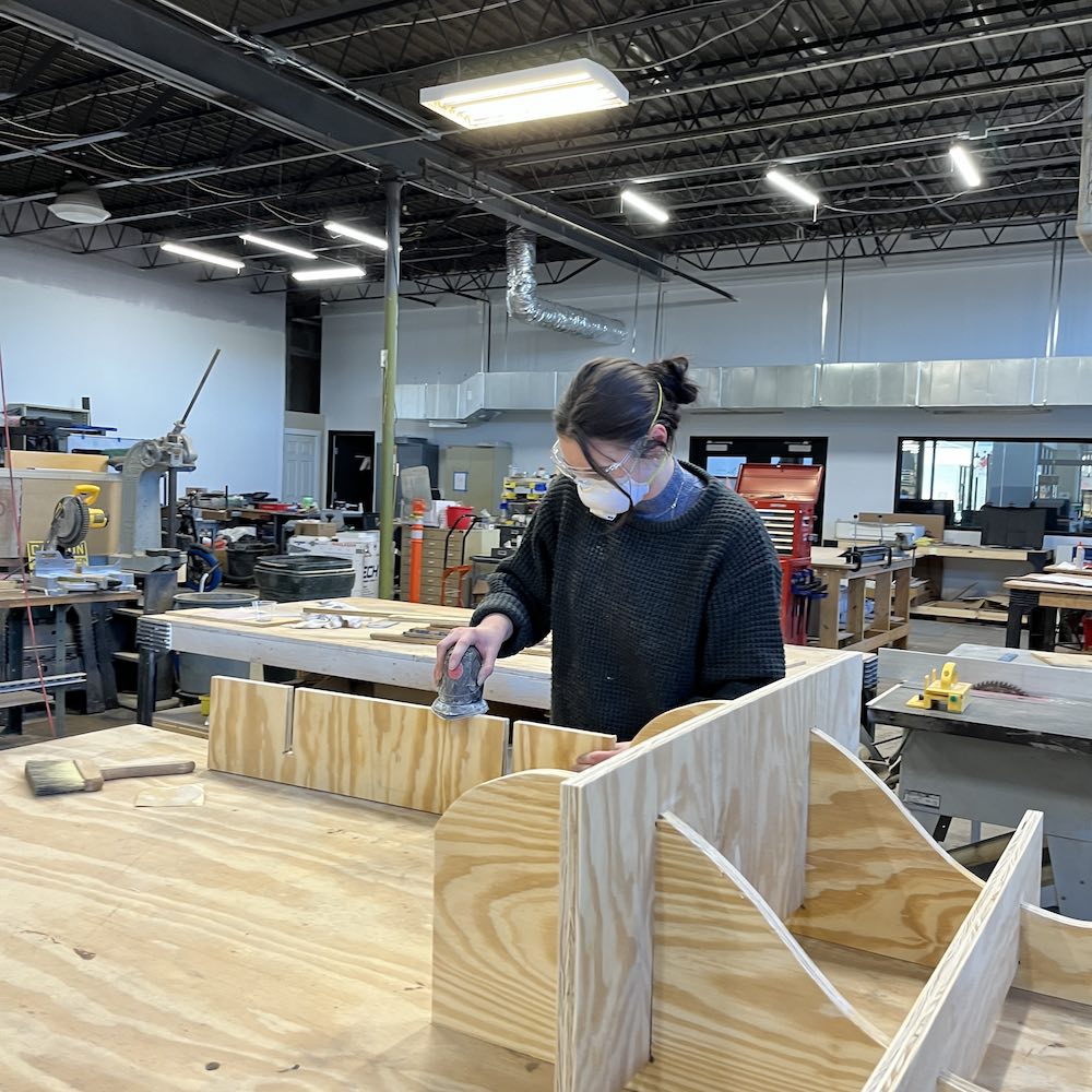
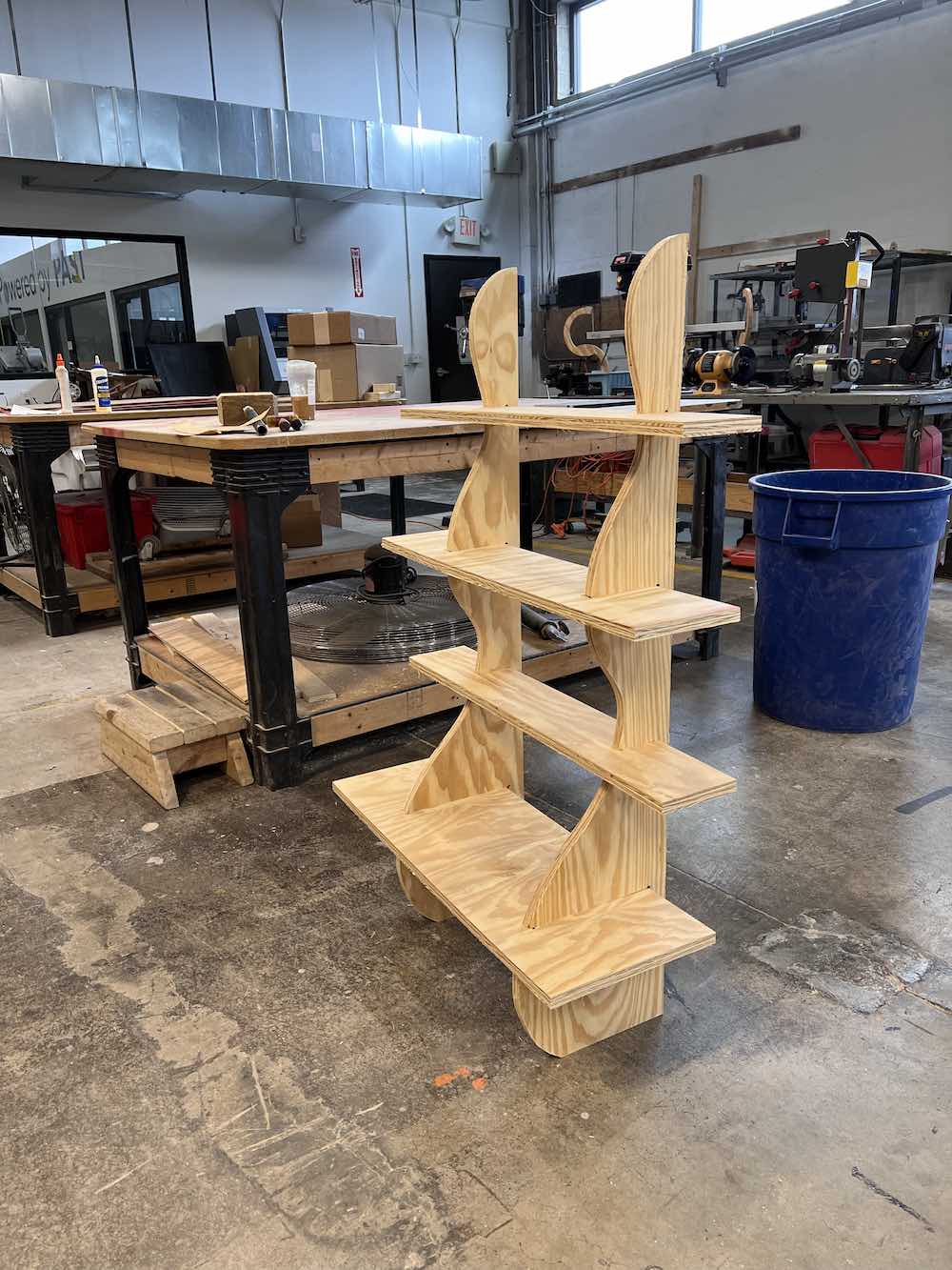
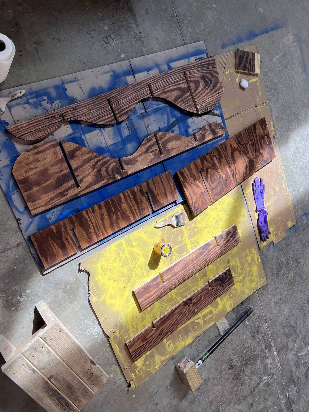
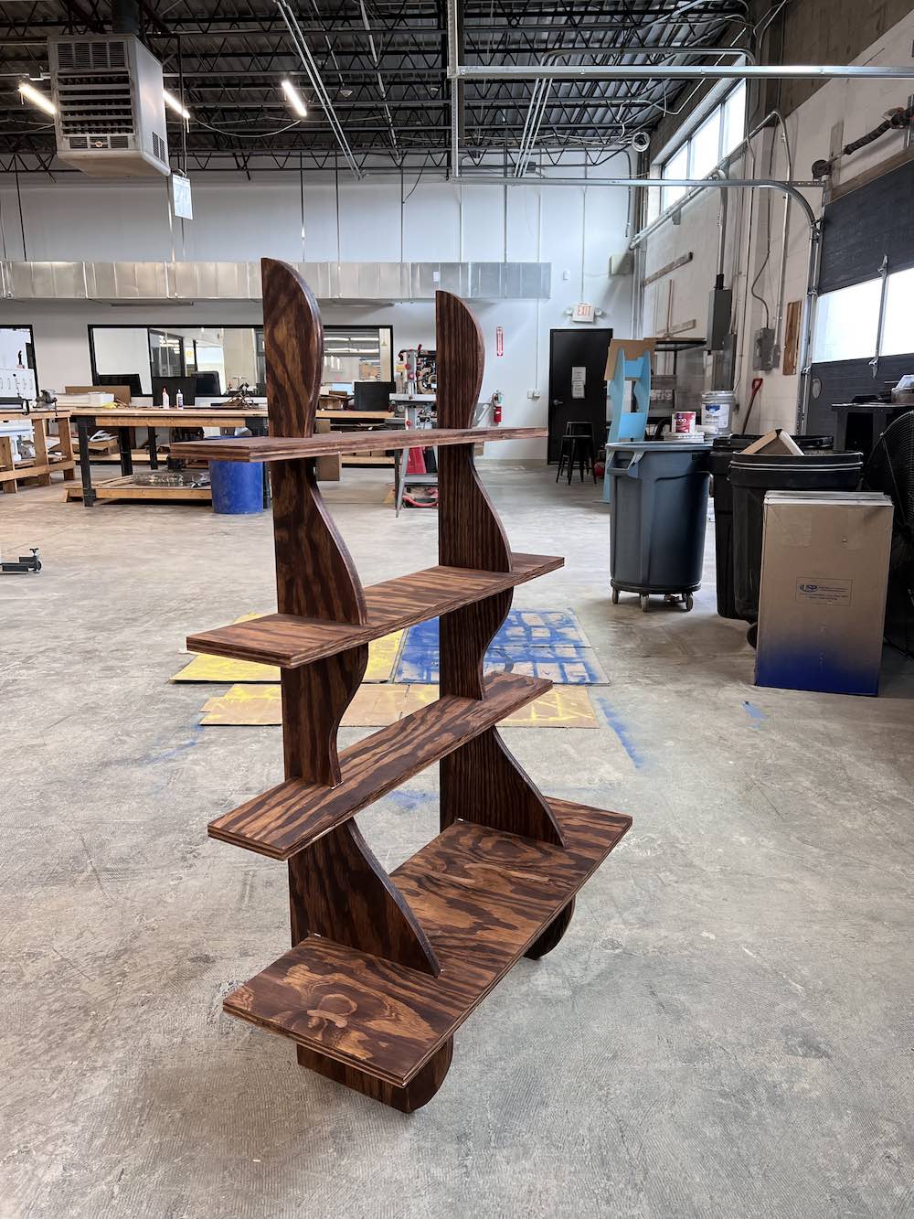
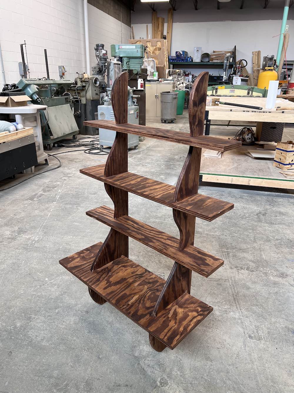
This is my final piece for this week. It is a bookshelf that requires no fasteners such as screws, nails, glue, etc. I am very happy and excited that I get to tell people I fully designed, cut, and assembled this bookshelf all on my own!