Week 9: Output Devices
Checklist for this week:
- ☑ Linked to the group assignment page
- ☑ Documented how you determined power consumption of an output device with your group
- ☑ Documented what you learned form interfacing output device(s) to microcontroller and controlling the device(s)
- ☑ Documented your design and fabrication process or linked to the board you made in a previous assignment
- ☑ Explained the programming process/es you used
- ☑ Explained any problems you encountered and how you fixed them
- ☑ Included original design files and source code
- ☑ Included a 'hero shot' of your board
Group Assignments
- Measure the power consumption of an output device
- Document your work on the group work page and reflect on your individual page what you did
Individual Assignments
- Add an output device to a microcontroller board you've designed and program it to do something.
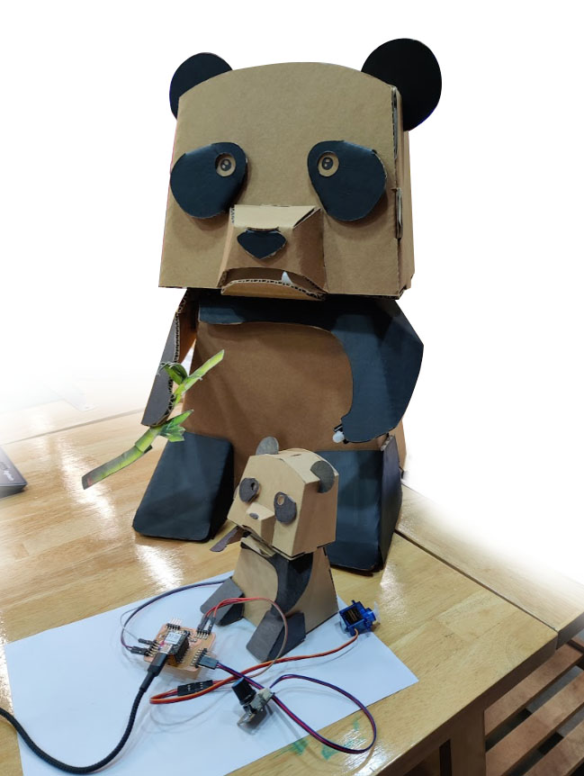
Hero Shot
Various Output devices
As a group we test output devices for our learning, e.g. LED light strips, OLED, LCD, DC motor, stepper motor and servos. Most of the output devices are self-explanatory.
Adding servos to the microcontroller (Trouble-shooting)
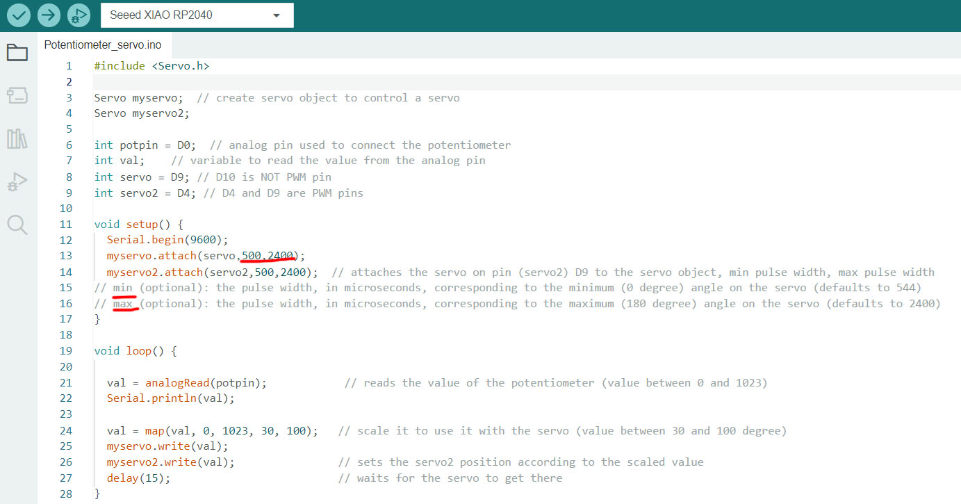
Code reference from Arduino Servo library Example Knob (Potentiometer)
One important note for the servo to connect to the PIN is that it must be PWM enabled (Pulse Width Modulation), e.g. D0 ~ D9 only (not D10).
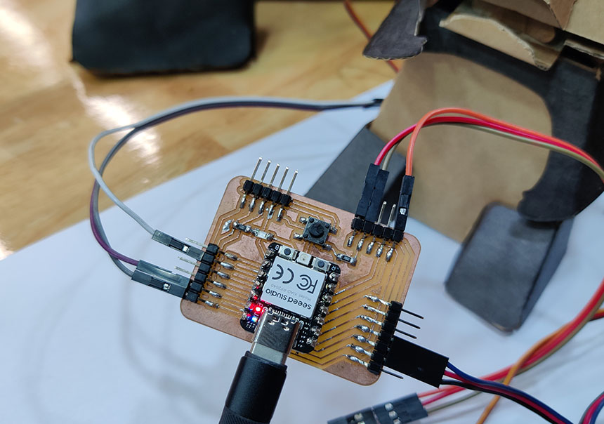
In this exercise, I try to power up two sets of servos. The signal pins from the servos connected to D4 and D9. The power connected to 5V instead of 3V3.
We import the "servo.h" library. Created functions for myservo, myservo2 and variables for potpin, val, servo, servo2. We used Serial.begin(9600) to read the value of the potentiometer (0 ~ 1023).
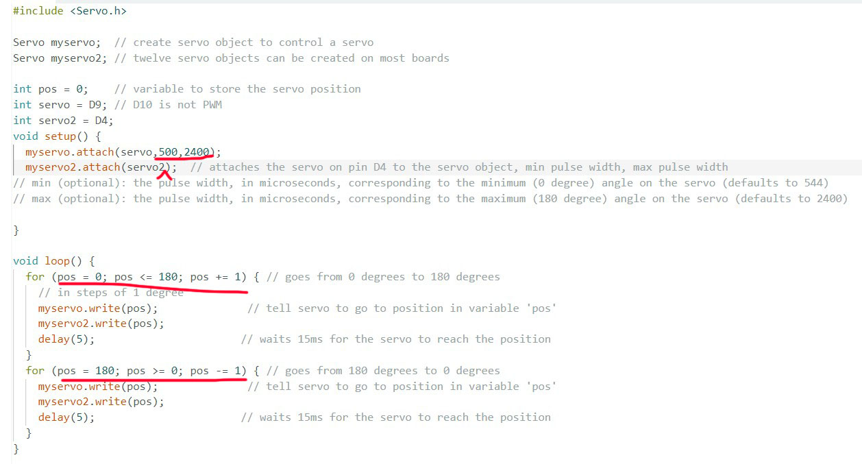
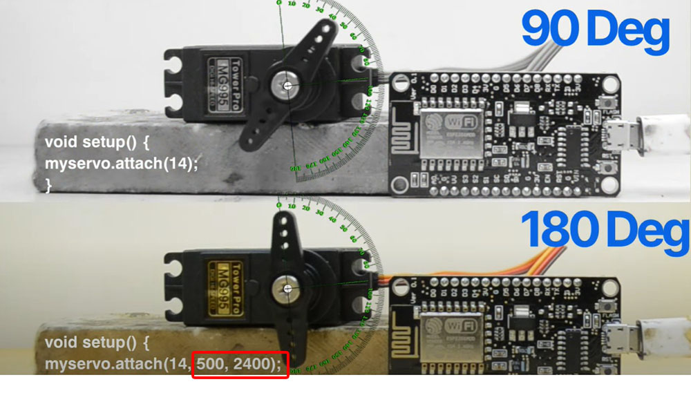
Min and Max Pulse Width of Servo
I have been working previously with servo in Arduino IDE but I have never encountered the servo limited to 90 degree of movement even though the servos are capable of 180 degree rotation. In my case, the specification of minimum and maximum pulse width in the code is compulsory to make it rotate up to 180 degree. More details to solve the issue in this youtube video.
Loading the code to the Pandas
The explanation for the rest of the code is written after the comments //.
Links to working files
- Arduino file for Servo -ino format.