Week _10: Mechanical Design
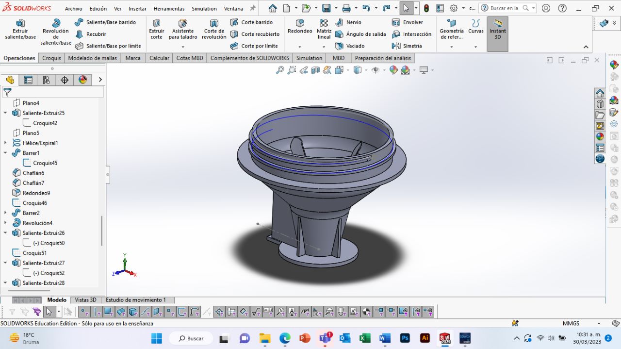
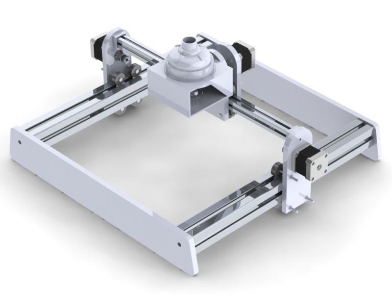
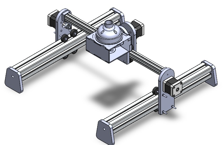
This week's assignment ies the development of a machine that can be automated to perform a certain task. Fortunately it is done as a team, all of us who are studying FabAcademy on the Puebla Node. You can check over here Team Machine Building the process of the whole machine done by the team. But the part I did for the machine are documented here. The design was made on Solidworks by the team members: Fávell Núñez, Maricruz Chávez, and myself.
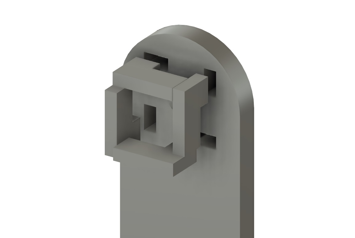
Most of the parts were laser cut based on the SolidWorks model, but i had to do a bit of modifications since it was originally designed for 3D Printing. The part where the aluminum profile is connected and locked was done with small 3mm MDF parts that fit on the 9mm MDF structure.
 I ran into a problem since all the pieces we had for the 20mm aluminum were very short and we needed a 44cm long piece. But the problem was solved with cutting the pieces in half and tapping the inner hole with M5 thread, and connecting both pieces with a long screw.
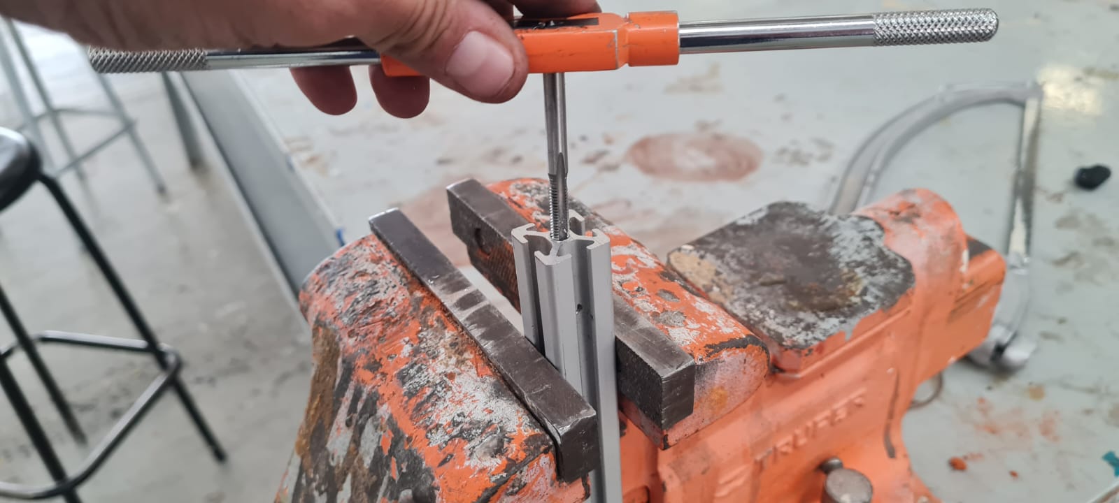 Having the piece it was a matter of tapping the 40mm aluminum profiles inner hole for M8 screws that hold the whole structure together.
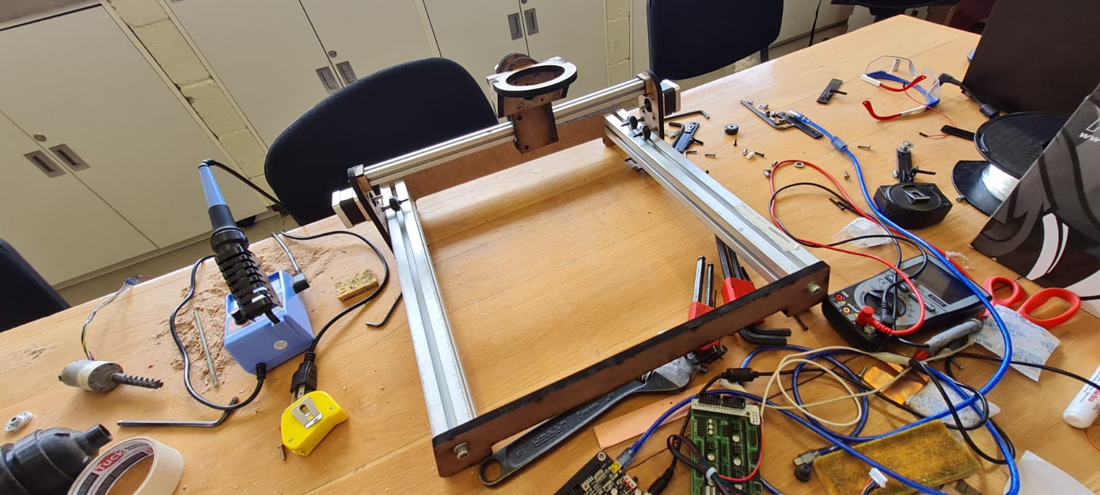 All of the digital design took into consideration the materials and screws we had available, so the building of the reel and mooving parts was like following a food recipe.
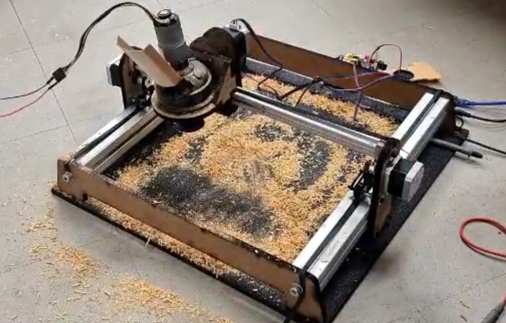
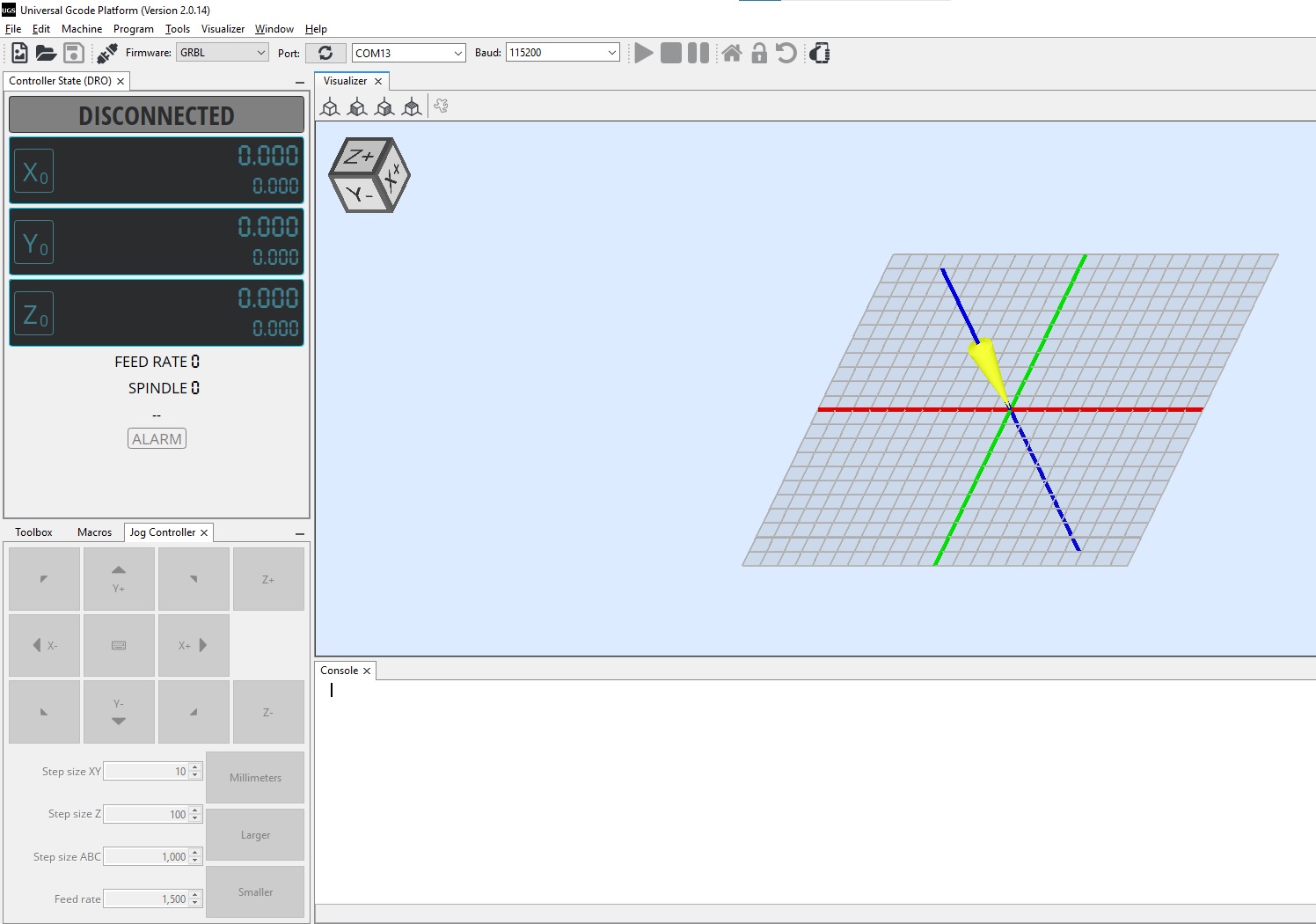
With the structure completed, we grabbed the CNC Shield and connected all of the stepper motors, modified a bit the PCB so it sends the signal to one X-Axis motor, and two Y-Axis motors, and no Z-Axis one. Firstly I connected the shield directly to my computer via USB cable, and using the Open-source Candle GRBL controller we were able to control the movement of the machine, and also to tweak the voltage/current that goes to the Stepper Motors by moving the potenciometer on the small motor drivers that go connected on the CNC Shield. we thought that was all, so we sent a g-code for it to draw it. The problem was that the machine "thought" it was very small, so it took it several thousand steps for it to move one mm, so when we sent the gcode, it barely moved on any direction. I did a small research about this configuration and came up with the software Universal GCode Sender which allowed me to program directly on the CNC Shield firmware by using the codes:
$100 = 83 and $101 = 83 which can be translated as: $100 means that the number of motor steps needed to move 1mm on the X-Axis is 83. The same number for the Y-Axis is configured using the $101. For future reference, $102 is used for the Z-Axis.
This number is not random, as we did several tests for the most accurate way of travelling 1mm on each axis.
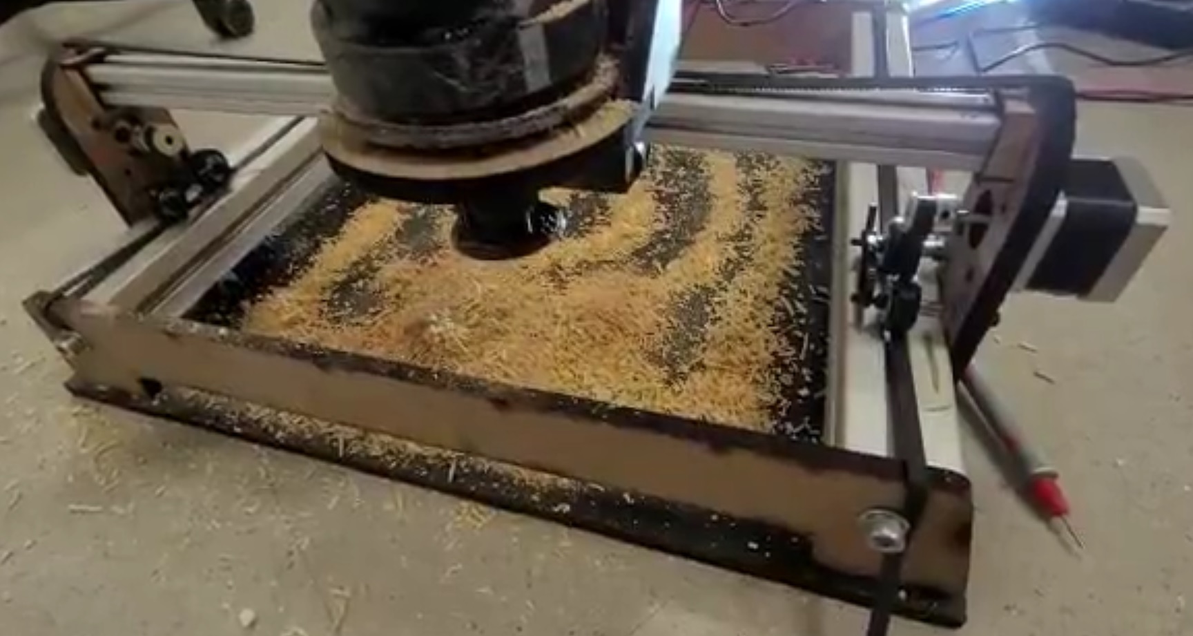
Having modified the firmware, it was time to send a gcode to the machine for it to draw it on sawdust. The resulting videos are our best test.
All of the files and process of design and building is explained on the Team Machine Building Website. See you next week.