Week_09: Output Devices
For this weeks assignements we're designing custom PCBs for different outputs, to be used on the microcontroller pcb we did Last Week. But let's start by defining what this concept is.
Outputs are devices that perform an action when triggered or programed. A simple example of Outputs is an LED, one can make it blink or turn on based on different factors like buttons or resistors. There are other kind of more sophisticated outputs like Relays, those serve
as buttons for circuits that do not belong to the same circuit as the microcontroller. Buzzers are examples of sound outputs, motors and servomotors can be triggered with a program also. The kind of analogic signals that can be used as outputs work with frecuency more than
voltage difference, and this is called PWM or Pulse Width Modulation. Imagine having a light source that can only be turned on with 3.3V, as an output it is possible to send that voltage, but this kind of light source cannot be dimmed with less voltage, so instead, pulses of a certain
frecuency turn the device on and off several times per second, that way the light intensity can be controlled.
Outputs can be Digital and Analog or using a Communication Protocol which means what kind of signal its sent by the microcontroller. Digital Outputs recieve either voltage or not. Analog outputs
recieve modulated pulses (on the datasheet of the microcontroller one can find the pins available with the PWM code). Communication Protocol Outputs recieve data or information.
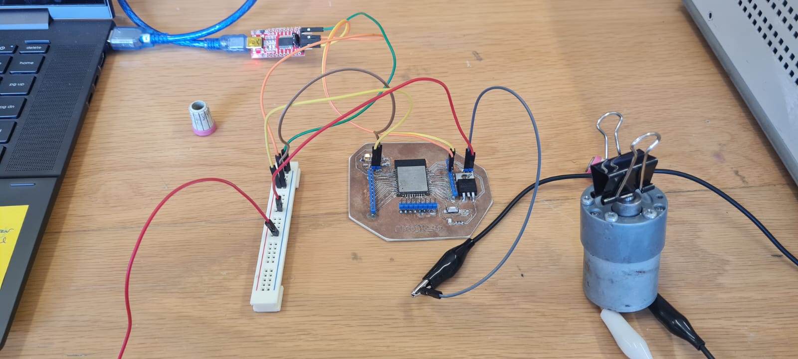
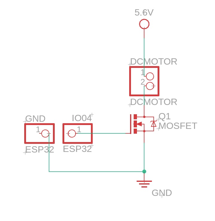
One can also use different "triggers" that can power on, or off, devices that use a different voltage than the one used by the ESP32 board, this kind of devices close a circuit like a switch, by getting a digital signal from the microcontoller, in this case I'm using a MOSFET (Metal Oxide Silicon Field Effect Transistors). I connected
the MOSFET's Gate, or trigger, to the IO04 Pin on the ESP32. By using the next circuit, one can control different devices like this:
int X = 1000; 		//Here I'm creating the variable X, which will be the time the DC Motor will be ON.
int Y = 1000;		//Here I'm creating the variable Y, which will be the time the DC Motor will be OFF.
void setup() {
pinMode(4, OUTPUT);		// Here I'm telling the program which pin is used for the MOSFET
	}
// the loop function runs over and over again forever
void loop() {
digitalWrite(4, HIGH);  // turn the MOSFET on (HIGH is the voltage level)
delay(X);                    	  // wait for X seconds
DigitalWrite(4, LOW);   // turn the MOSFET off by making the voltage LOW
delay(Y);                  	   // wait for Y seconds
}		//Since all this chunk of code is between the "{}" of Void Loop, it will be repeated indefinitely.
And the code works!
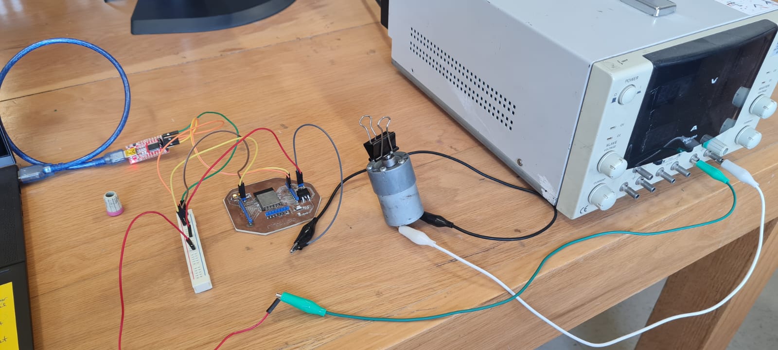
The motor is a 12V DC motor from Pololu, with a 6.3:1 reduction gearbox. It's time to measure the consumption and power of the DC motor, which can be calculated with the next formula:
Power (Watts) = Voltage (Volts) * Current (Ampers)
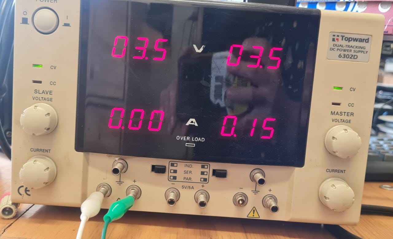
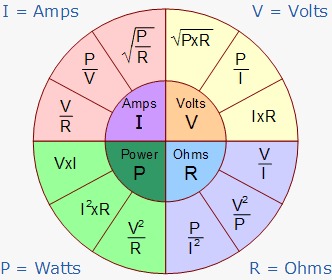
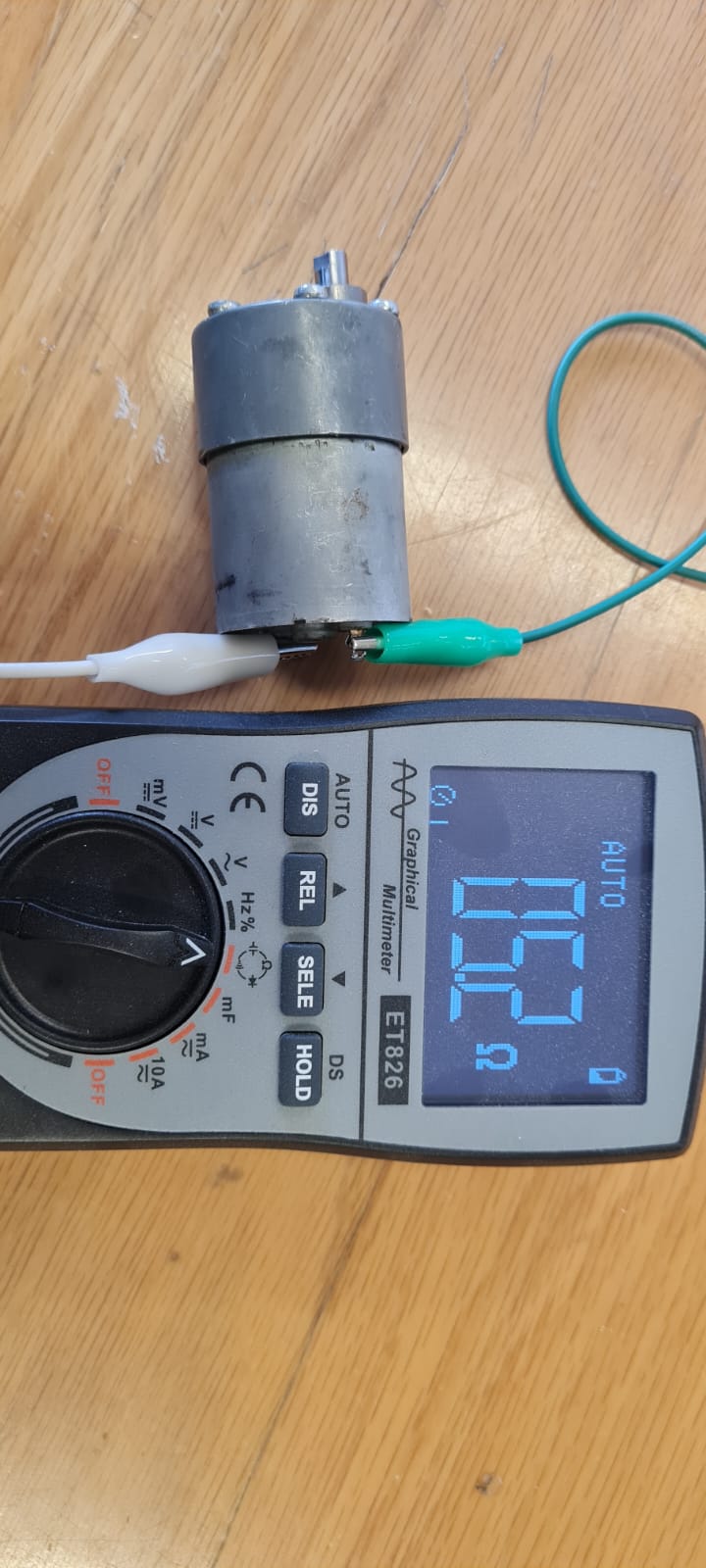
3.5V * .15A = .525 Watt So we can determine that the resistance of the motor is 3.5V/.15A = 23.3 Ω so I measured it with the multimeter and got a different reading,
but that can be due to the extra power the motor needs because of the gearbox that gives more torque but reduces the speed.
The Programming
Now that we know the code works I'm going to explain really quick how the programming of the custom PCB I designed was done. There is this pair of pins on almost every microcontroller board called Rx/Tx, which are digital signal pins. Rx pin listens to the signal that is sent by a Tx pin, this two are associated with the Universal Asynchronous Reciever Transmiter (UART), also denominated Serial Port. The UART converts the byte into a serial stream of 8 bits and start, stop and parity. In this particular case I used this USB Serial interface to connect the Arduino IDE to the ESP32 embedded on my PCB, all done through the Rx and Tx ports as indicated on the next Image. The Tx from the interface goes to the Rx of the microcontroller, and viceversa.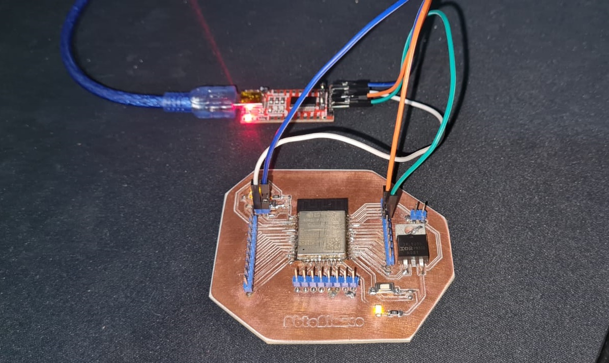
I found a bit of an issue while trying to upload the code, as the
Boot button i added on t he PCB is built as a Pull-up, or normally closed, button. The solution was to just keep pressing the button as the code uploads and everything went smoothly from there. I am doing the propper corrections for the next iteration (the 20th) of my circuit design.
I have included the code for the Arduino IDE on the Downloadables webpage and I recommend to check the previous weeks for the design and process of building the PCB.
See you next week.