3. Computer controlled cutting
This weeks assignment was to learn about computer controlled cutting with vinyl cutter and laser cutter.
With laser cutter we first got to know some safety rules, and then focused on understanding laser cutter parametres. As a group assignment we were to characterize the lasercutter's focus, power, speed, frequency, kerf, and joint clearance. We documented our work to the group work page which is on our Fablab Oulu pages. Check out our findings there!
My own reflection:in group assignment we learned about the affects the settings have on cutting and engraving, and about the kerf. Some of it I already had learned before in my work, but it was interesting to see all the variations the settings produced. For example with cutting it was good to see how important it is to set the speed value correctly. Sometimes depending on the material and its thickness, the cut does not happen even with 100% power if the speed is too high. Then testing the DPI was interesting too. We noticed in our test piece that both DPI 300 and 600 were good, but the result of course depends also on what you are engraving. For example engraving a photo would benefit from a bigger DPI.
It was fun to experiment on cutting and engraving, and see how the kerf affected to cut pieces. What was entirely new to me was that the kerf can vary between x and y axis. I later read it also varies between straight line and curved line, and diagonal lines. I don't yet understand why but this is very interesting information. Could the beam sometimes exit at a slight angle? For example when making boxes the difference might affect the joints fitting together.
It is said that for example focus, power, speed, material thickness and properties effect the kerf but I have also heard a quote that managing kerf is about as reliable as herding cats. So it is really important to always check for the kerf before cutting your work.
I felt after this assignment I was ready to move on to the individual work.
Go to:
Vinyl cutting
The design
After the group assignment I decided to first make a sticker to my laptop with the vinyl cutter. I wanted to cut a sticker of Kickboxing team Oulu's logo I'm also using on my final project. Last week I touched upon the subject in computer aided design and specifically on Inkscape. I had a file of the logo, which I had already last week brought to Inkscape and turned into vector design with Trace bitmap.
However, my coach showed me once an older version of the team logo which was in a shirt, and I liked it even better. But I only had a photo of that shirt and not the actual logo file. I decided to edit the logo I already had, to make it resemble more of the old logo and also fix some problems there might be considering vinyl cutting.
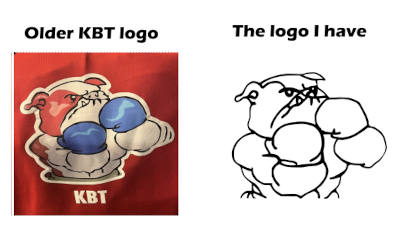
First I wanted to change some little things on the appearance, for example the face and the ear of the bulldog. Then I focused on making the design optimal for vinyl cutting by fixing some of the lines and making new ones like on the belt. I also wanted to minimize the amount of tweezing by making almost everything as a one line.
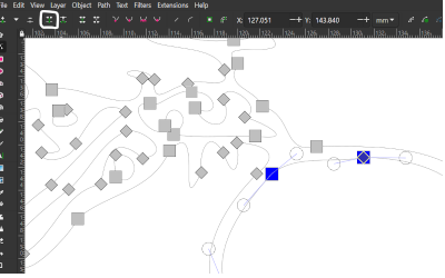
I joined some lines together by choosing the nodes I wanted to join and then pressing join selected nodes on the tool box. I sometimes added nodes with insert new nodes and also took some extra nodes away with delete selected nodes. To make some nodes smoother, I chose them and pressed make selected nodes smooth and I also used make selected nodes corner to have sharp edges. These tools are all on the same line on top.
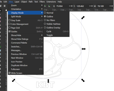
At the end I double checked if everything was alright by choosing outlines on view. Everything was fine! Then I just added a circle around the design so that it will be easier to remove the vinyl after cutting.

Cutting the design with vinyl cutter
When the logo was ready to be cut, I went to our Fablab. Luckily the instructor of the week was also there, so I knew I could ask for her guidance if needed. And I did.
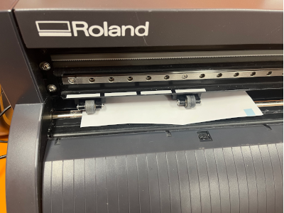
I went to open up the computer and pressed the vinyl cutter on also. The machine is Roland CAMM-1 GS-24 desktop cutter, and it has a computer next to it to use for the printing. We were shown in our local lecture the main points to remember when using the vinyl cutter.
The sticker vinyls were in rolls, but there was also boxes that had smaller pieces of vinyl that you should always check first for your needs. I found a suitable piece of white vinyl, and put it into the vinyl cutter. The origin of the print on the printing program is on bottom left corner, so I tried to place the vinyl piece in a way that the cutter would go on the bottom left corner of the piece. The pinch rollers go to the corners of the piece, and they should be placed accordingly to the grit marks on the machine. When everything looked alright, I pressed down the switch that locks the vinyl piece.
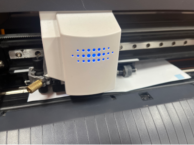
I used the arrows on the command module to search for Edge and pressed enter. The cutting head started moving to in between the pin rollers. The screen showed the width of the piece which was ok. It was ready to be used!
Then I went on to the computer and opened my logo file in Inkscape. When it opened, I made sure the whole logo was active and then I looked for the Cut studio extension.
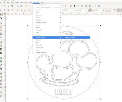
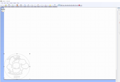
In the Cut studio the logo was automatically on the bottom left corner. Then I just pressed ctrl+p for print, and sent it to the vinyl cutter!
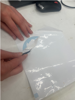
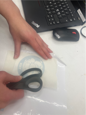
After the cutting was done, I removed the vinyl piece and checked everything was as it should be. It looked nice, so I turned off the vinyl cutter and went on to work with the cut. I used tweezers to remove the parts from the cut that I didn't want to use. That wasn't an easy choice, as I felt it could've been a great sticker in many different ways. In the end I chose to remove the background and the cut lines so that only the middle parts were left. The tweezing went nicely, since the cut was made perfectly and because when modifying the logo I made sure almost everything would be picked off in one piece. I was very happy about this! After that I just pressed the transfer material to the sticker and made sure it took off everything. Only on the small eye part I had to use scirrors to press it so it stuck to the transfer material.
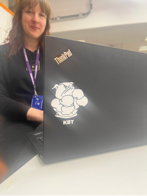
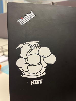
Now everything was set to placing the sticker. The laptop cover was first wiped clean with something alcohol based. Then I looked for a nice place, and just pressed the whole thing on it carefully but firmly. When I peeled the transfer material off, everything went beautifully and the sticker was now on it's place. I was very happy about the result. Thanks to our instructor for the photos and for the help!
Press-fit construction kit
Planning
The biggest effort for this week was to design and cut a press-fit construction kit. It had to be your own design and it had to demonstrate and describe parametric 2D modelling process, and mention processes used with laser cutter.
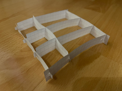
I saw some of the work done in earlier years, and had problems deciding what to design. I wanted to be able to use the kit myself and I wanted it to look somewhat pretty. My head was again first empty, then full of ideas, and I had to pick something that would be actually possible to do in this time frame. So a picture arised in my head of a box that could be used as a decoration or holding something in it. My 3D imagining skills are not that good, so I made a quick prototype of paper to understand the project.
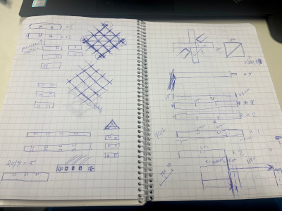
I also made some drawings and calculations to my notebook. It was very much needed to understand the dimensions.
3D design
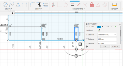
Then I just opened Fusion360 and got on with it. I started with the first piece that would be in the middle, because I thought that would be the easiest to start with. I drew a rectangle and added a small rectangle to make a slot. I decided it's placement on the body, and then copied it so that there was 3 slots spread on the piece. At this point I started adding parameters with Modify -> Change parameters -> add a parameter. I did a SideClearance -parameter that orders the placement of the slot from the border of the piece, and I did MaterialThickness and Kerf parameters to assign for the width of the slot. In the process I ended up doing loads of parameters, for example height of the piece and height of the slot.
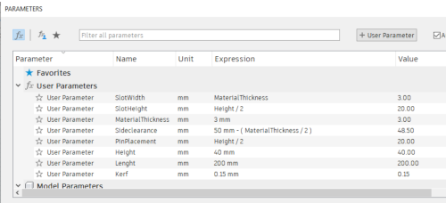
I was adding the parameters in too much of a hurry, and didn't stop to think. So there is a parameter
SlotWidth = Material thickness, and
Material Thickness = 3 mm.
The Kerf parameter I added later, and then in the design I just referred to it when needed. So when I did a slot, I set the Width of the slot to Material Thickness - Kerf. That does the trick; if I ever change either material thickness or kerf in parameters these slot widths will update themselves. But the shorter way would have been just to modify the
Slotwidth = Material Thickness - Kerf.
That is one of my problems; when I feel I'm in a hurry and there's lot's to learn I tend to get a bit frantic and the quality of my work can suffer.
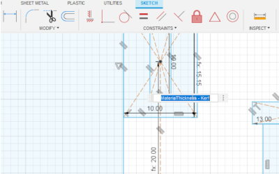
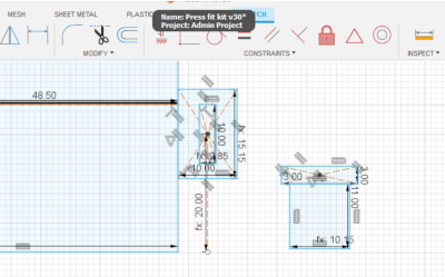
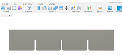
Here is an example of me defining slot width. This is the finger/tab and a slot that are in the wedge joint. In slot width the kerf is subtracted, and in tab width it is added.
My bodies/elements were not that different from each other, so I basically modified the lenght when needed, added the slots I needed, added some fingers and then one new interesting joint I remembered from global lecture. I think it was called wedge and I had seen one previously in some old woodwork. I designed one I thought would work and added that to one of the pieces that will make the frame (with 3 other copies of it). I designed a finger with a slot with the dimensions I needed, and also the counter part to the other end of the piece. Then I made the actual wedge. Other dimensions I decided myself but the slot width had to take into account the material thickness and the kerf and the finger width the kerf. The finger pieces were joined to the body by their lines and coincident constraint.
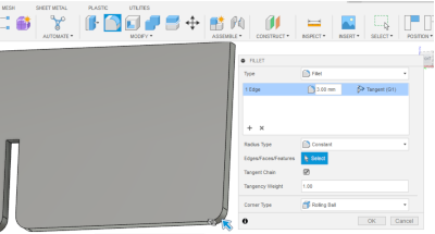
Then I extruded the pieces and made some fillets so that the pieces could fit together possible more easier. Fillet is found under Modify -> Fillet. Just select the edge and put in the tangency weight wanted. When I did this I was very tired and my head was not working. Therefore I pretty much did one corner at a time instead of choosing a bunch of them. Live and learn!
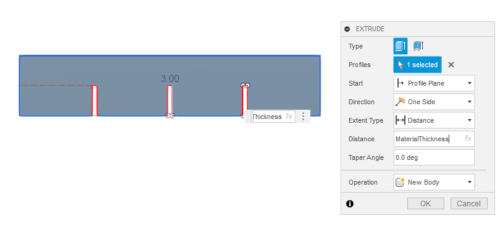
After all this I extruded all of the pieces and set the value to parametre MaterialThickness.
Here is an example of a ready piece!
By the time all this was ready it was Sunday evening. I had a few hours of FusionFun behind me (because I'm still learning) and I had success and failure and repeat. I was quite tired when I tried to bring all this to a file that I could then open in Inkscape. First I tried the original design file, but I had no luck with it in Inkscape. Then I remembered I had heard that the drawing would be a good way to go. So I started making the drawing (from Design -> Drawing -> From design.)
I created the drawing from full assembly and checked that the units were mm. Sheet size was A3. When I waited a bit, the drawing magically appeared in front of me! But it was much bigger than the A3 as the pieces were all scattered around. I checked if the scale was ok and it was, 1:1. I thought I would anyway try to export something out to see if it works.
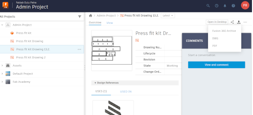
Well that wasn't so easy! There is an PDF export image on the drawing windows upper right corner. I pressed it, but there wasn't an option to load to my computer. I only could load it to web interfaces file. I went to see the files in my project, but there wasn't an option there either to upload it. In the drawing I found one upload link also on upper left corner, but it was on grey and it was not possible to choose it.
At this point I went throught various searches and guidances people had wrote, but nothing helped. I was so tired I felt angry and sad and my head was exploding. I did my best but it wasn't enough.
The next day, as I had lost all hope, I asked help from a couple of instructors. I good advice in making the drawing: I had to bring in every body/element individually to get them to fit to the A3. But we had still problems on finding how to download or save the pdf to my computer. After a lot of trials and errors, I finally understood to open the pdf file from my Admin file and then there was a place I could make the download!! It wasn't enough to go to the file and press the dots in the side, but I had to double click it to open it to this view. Very simple in the end, but it most definitely didn't feel like that for a long desperate time.
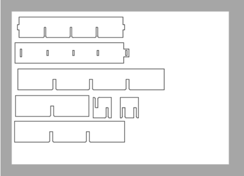
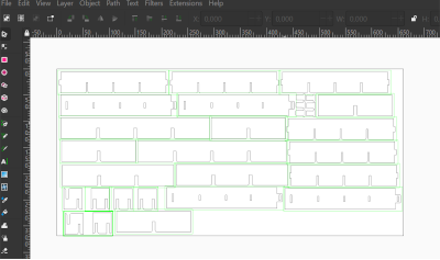
After this the sun finally came out and the birds started to sing. I had no problems opening this up on Inkscape. I imported it there, ungrouped the objects and placed them as I wanted. I multiplied the pieces to fit my needs. I also made sure the stroke was set to 0.02. Then I just saved it as pdf for our laser cutter.
Laser cutting
I can't believe it was working! Now the only thing left was to laser cut this..and then I would of course find out if my calculations had been alright or not. I went to Fablab and checked the material we had on offer. My instructor said that I can use MDF if I'm planning to make a decoration or something that I will use and therefore cardboard might not be the best choice. I chose the MDF we had, which has a white coating on it on the other side. I have previously used this material and the kerf and material thickness I measured was the same I already had on my parametres so I didn't have to change it.
Before starting to laser cut, I checked that the air input and output are on. The input means air assistance and that must be activated to reduce the risk of fire. The output/exhaust must be activated to remove the dust, debris, smell and toxic gases.
Also when you are working with the laser, you never leave it unattented. This way you can see immediately if something would go wrong. You can pause the work, and for example if you see fire you should suffocate the fire.
At the end of the job, you must also wait for at least a minute to let the toxic gases and smells to be removed.
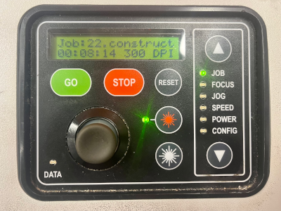
The printing process was straight forward. I opened the pdf and pressed print. In the laser cutter printing settings I chose a pre-made setting "3mm MDF cut" which is made for vector. The speed was 15% and power 100% and that was just how I wanted it so no changes. I went on to print. In our laser cutter Epilog Fusion M2 40 the cutting starts from the upper left corner of the drawing, and that was the place I also set the focus in.
In the laser cutter I placed the material to the table and first set the focus. With Jog I moved the laser cutter head to the upper left corner and put the measurement device on it. I moved the table up or down and as the measurement device was touching my material, the focus was right.
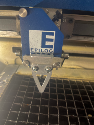
In the control screen I moved around with the arrows. I used Focus to set the focus. I used Jog to run the laser head to my wanted origin (upper left corner) and pressed it down to set it. After that I went for Job to choose my file which was already there visible. It had also made an estimate of the time the work would take which was about 8 minutes. Then I just pressed go!
The laser cutter and the settings worked out beautifully. There was only one small part I had to force out of the board, everything else dropped off nicely. I cleaned the pieces first, and then very hesitantly started to see if they fit together. I was very happy when I heard the first click! After playing around with them I did notice it was not 100% perfection, but very near. And I was also very happy about the wedge joint, it worked out very good!
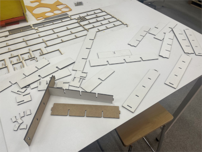
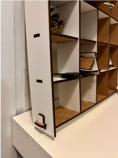
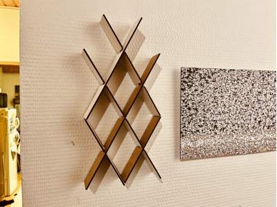
I had done some extra pieces that I thought I could use either in adding them to the box frame or using them as a separate object. I did try to add some of them to the frame diagonally, but the slots I designed for this were just a little bit too small. I could've just taken some surface off with sandpaper because the difference was so small, but I decided I wanted to play with them and make another object. In both objects I also varied the direction of the pieces so that I got to play with a white color surface and the wood color surface.
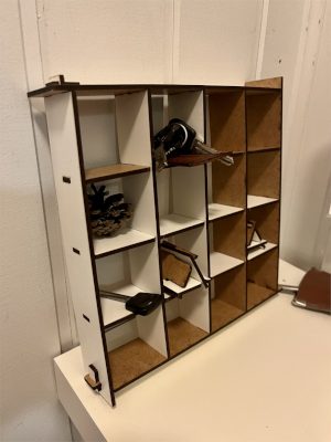
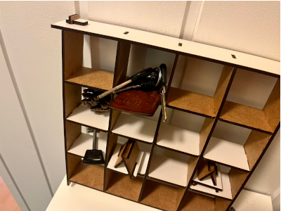
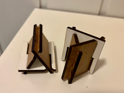
When I got home, I wondered if I would use them as a decoration or something useful. I ended up with both! The original box frame is going to be used a box system for keys, and the other design found a place on the wall. I also made as a test these very small objects I cut and made small triangle shapes with them. They came out quite cute!
What an experiment this was. I got used to parametres, learned a lot more about Fusion, learned that there's no sense doing anything when tired, and also found out that I can actually imagine and ideate a project and make it come through! Who knew.