2. Computer aided design
This weeks assignment was to model experimental objects or parts of your final project in 2D and 3D software. My idea for a final project is a reaction time game for kickboxers.
We started with our local lecture session in which we were first explained about modeling process. You have on idea, which you model in 2D or 3D, check the measurements and dimensions, and then move on to fabrication. We were shown a few tools for this, and also got some recommendations and tips from our instructor. There was a lot to learn so I basically treated the lecture as a review around the subject, and had an good idea what programs I would start with.
In this weeks assignment I will be using Gimp for rastor images, Inkscape for vector and 2D design, and Fusion360 for 3D design. Gimp I have only used for image resizing, but I have some previous experience on Photoshop and Photopea so that should go nicely. Inkscape I have used for designing for laser cutting, but at the beginning I don't yet have a clear view on how to present my final project with it. That will be interesting.
But the ogre in the room for me is Fusion. I have no experience in that, and really looks confusing. So I have a lot on my plate this week.
Go to:
Gimp
I didn't have a clear idea on what to present with Gimp this week. It could've been a logo for my final project, but because I've got my work cut out for me with Fusion, I would like to keep it simple. I found a nice tutorial our instructor had left us on a toolbox on our wiki. The tutorial in PhotoEffect was about making a blueprint-looking image.
My final project has LED reaction lights on it, and they will be in a form of LED rings that also have some kind of sensor in the middle to react to touch or proximity of a hand. I don't have any photos of LED rings and it would take a long time to draw one, so at first I searched the internet for a photo of reaction light LED ring since I know they exist. I found one, and used the tutorial to make a really nice blueprint effect image. I was very happy with myself. Until..I realized the photo had copyrights and was not free to be used at least without asking permissions. I didn't have time for that, so I had to search for something else.
Of course there weren't any free photos lying around of these LED rings. So I had to find something else, and finally agreed on a photo of a motorcycle lamp.
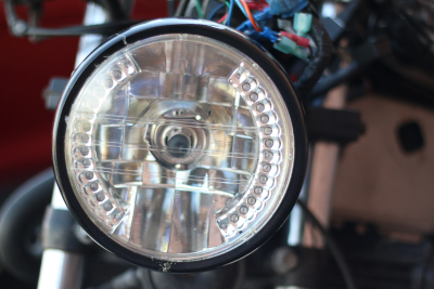
My first photo did justice to the blueprint -tutorial, but this one didn't. So I changed some of the settings. Still I didn't get what I had my mind set on..but still this is a raster image of a round object with LED lights and therefore has something to do with my final project idea. With this assignment it was clear to me that I want the lights in the final project be in a circular shape.
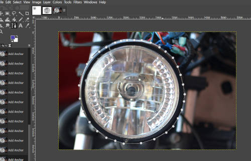
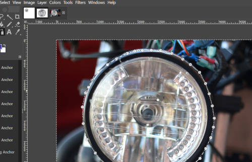
Here's how I played around with the photo.I used the Paths tool to trace around the image I wanted to keep (the round lamp). I started by clicking once to place an initial anchor point. I continued by clicking to set anchor points along the lamp to create a path. Then I close the path by positioning the Paths tool over the first anchor point and clicked.
Then I inverted the selection so that only the lamp would be left. I used Select -> Invert (Ctrl+I) to invert the selection. Now all of the layer contents which were previously outside of the selection are inside of it.
Then I used Edit -> Clear to delete everything in the current selection, and only the lamp was left.
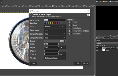
Now I made a new layer, because I wanted the lamp to have a white background. I used Layer -> New Layer to create a new layer and I chose it to have a white background. I also dragger the new layer beneath the headlight layer so that the lamp would be in front.
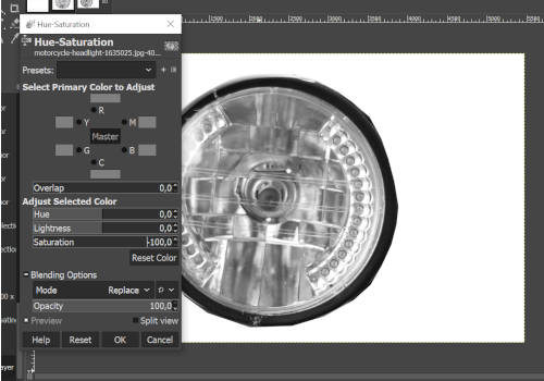
Next thing was to desaturate the image's layer. I made sure the image's layer is selected, and used Color -> Hue-Saturation to desaturate. I dragged the Saturation slider to -100.
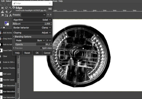
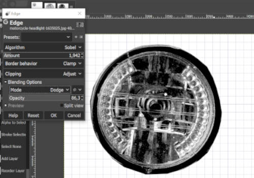
Then I used Edge to transforms the image's layer into a line drawing. I tried different blending options to find one I liked, here are for example Burn and Dodge.
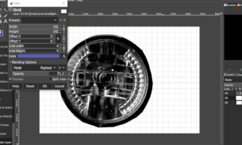
Finally I then added a grid to make this image look like something that could be drawn to a notebook. First I used Layer -> New Layer to create a new transparent layer for the small grid pattern. Then I used Filter -> Render -> Pattern -> Grid to create a small grid pattern. The color was set to what I thought would look like notebook grid blue. I set up 192 for both height and width of the grid, and adjusted the layer's opacity to about 70%.
And here is the result!
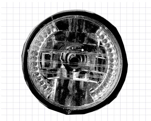
This short exercise gave me some additional tools for Gimp, for example the grid function I had never used. I have also started to think about the actual LEDs in my final project; how many will there be in the ring? Also with this I got a reminder to always resize the images, since I totally forgot to do that to my screenshots at first.
Inkscape
How to visually represent my final project in 2D? I'm sure there exists some great ways, but my brain is absolutely empty right now. I amused myself by creating a model of the whole thing and it looks like something you could make with Paint..but it did gave me ideas and things to think about and that way it was good.
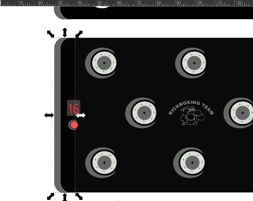
This is it.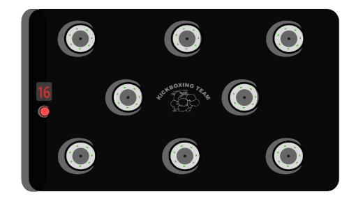
There is a board, 8 LED rings and their holders, start button, result screen and a logo in the middle. I'm planning the LED rings to have some kind of holders, for visual sake but most importantly for safety. Whether the LED ring is deactivated with a light touch or with just approximity, there is always a chance for accidental contact. And when you are talking about kickboxers, an accidental contact isn't always soft. First I was thinking the holders could be 3D printed, but if I want any flexibility on the rings, it could be made on the molding week from rubber or silicone etc. Also there should be some kind of material covering the rings, letting only the LEDs and the sensors show. I must discuss this with the instructors since I don't yet have enough knowledge of the subject.
The board could also be made with just 5 rings.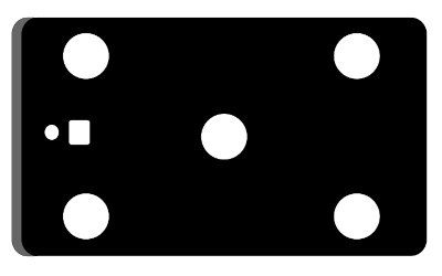
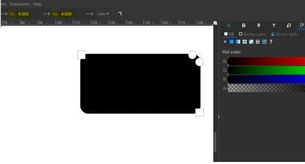
The board in the model was made with Create rectangle -tool. I set the fill black, and I made the corners more round by seting Rx & Ry to 5.
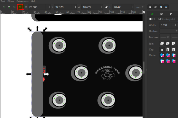
Then I made another small rectangle in grey color, to help me represent the box-like form of the board. I chose the grey rectangle, and used the Lower selection to bottom to move it under the black rectangle.
Here is how I made the LED rings and holders. I only used Circle tool with different fill and stroke options to make all the circles. So there are 4 different circles and then the shape made with Bezier tool.
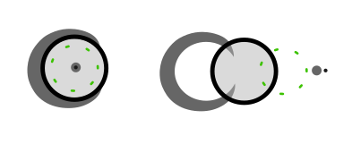
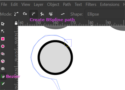
To represent the holder of the ring, I used Draw Bezier curves drawing tool with BSpline path. That one makes the curve smooth automatically. I used a circle as a help tool to draw the line.
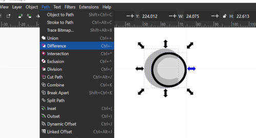
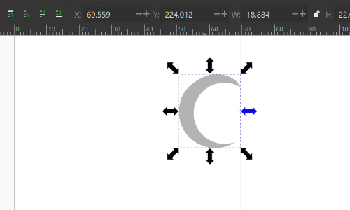
After drawing I double clicked to set the path made. Now it still needed to be modified to make perfect cresent moon shape to represent the holder. So I chose both the circle and the path made with bezier tool, and chose Path -> Difference.
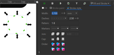
Here I presented the actual LEDs with a circle tool by taking the fill off and defining stroke style with dots and stroke fill with green color.
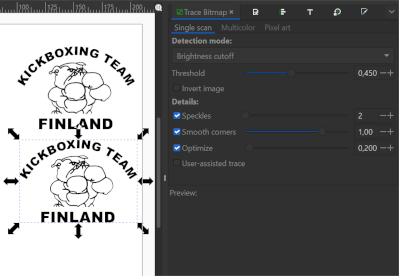
Then the logo of my kickboxing team I took from the internet because I know I have permission to use it. It was in png format, so I made a vector image from it by Trace bitmat and edge threshold of about 500. Originally I was thinking that the board could be painted black so that the LED colors would pop out of it nicely. But if I carve for example this logo or anything else to it with laser cutter, it won't be that noticeable. This is something I have to think about.
With this experiment with Inkscape I started to think about the spread of the rings, the actual dimensions of the board and how to get the best functionality out of it. One thing to think about is also how to make the packaging. The board should not end up being too heavy, and I would like it to be moderately easy to move around. Should it be attached to a wall or have something to hang it with for example to railings?
Fusion360
Now the fun part starts! How to tackle the impossible looking oger-software called Fusion360? Answer: very carefully.
First I thought about the parts I actually would like to try to model. The first one was the ring that has the places for the LEDs. As I know nothing about Fusion360, I start with a scared but an open mind. I assume the first step is to create a sketch and name it. Then I just drew a circle with a diameter of 100 mm.
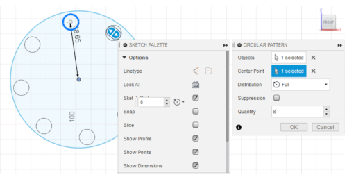
I drew a smaller circle, and tried to extrude. Then I realized I can't just randomly make circles and extrude them one at a time, because first of all they need to be placed evenly and with the same dimensions. At his point I thought it would be better not to invent the wheel again, so I searched for instructions on how to make holes to a circle so that they are aligned properly. I found a nice tutorial from 3D distributed I started again from the first big circle. I made a smaller circle inside the first one and pressed d to set the vertical distance from origin of the bigger circle. Then I chose create -> circular pattern and chose the centre point of the smaller and then the bigger circle. Quantity was 8 because I wanted 8 smaller circles. Then I pressed e for extrude and chose the smaller circles to make the actual holes.
At his point, I also needed a bigger hole in the middle so I made another circle and extruded that. Then I noticed my ring was very flat, and I needed to use edit feature and pull it some depht. All these commands and where they are found is just manual work, since the program is new to me. Trial and error..
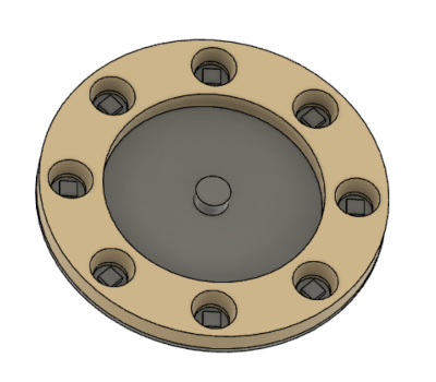
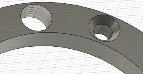
Here is a picture of the end result!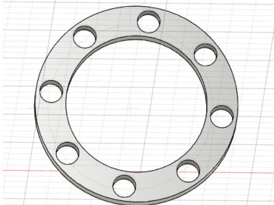
Now I noticed that it would be nice to have the holes to carry out the light of the LEDs as good as possible. I wanted to expand the holes so that they are smaller in the bottom part and widen up gradually. I tried to modify a hole in its editing window, and this was the best I could come up with.
That wasn't enough for me. I met my instructor after this, and casually asked him if he had any tips on how to do this. Be careful when you ask for directions from a fab instructor, they might become a bit enthusiastic about it.;) Gladly this question led up to me learning so many things about Fusion that now I actually start to understand how impressive the program is. That said, I need to do a lot of repeat to really learn the processes and be comfortable with them.
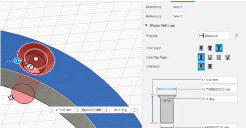
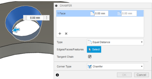
This kind of project needs surface mounted LEDs, and for the modeling I used the size 5x5x1.5 mm. So I checked that the holes are big enough and they are. For the effect of the holes widening up I was instructed to use the Modify -> Chamfer. Chamfer and fillet are used to bevel and round off the edges of an object. You choose the side of the hole and just pull to directions and decide what looks good for your needs.
The next thing was to create the LED PCB that goes under the ring. I created a circle to be the size on the LED ring, and the thickness by the the PCB we have is here which is 1.6 mm. Then I wanted to ground the PCB and build on that.
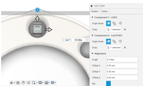
I joined the PCB and the ring together with Assembly -> Join. I chose the origin of the ring by pressing ctrl+origin, and the origin of the PCB just by clicking. Now the PCB was ready and in place.
Then I created one LED with the size 5x5x1.5 mm. I used one of the small circle's mid point and placed rectangle there with a center rectangle tool. I made an coincident constraint (two points constrained to each other) with the origins. I extruded the rectangle to it's wanted size. Then I did a joint to the LED and the PCB (from -> to). After that I used the circular tool to repeat the LEDs to around the circle. I chose first the LED body, chose y-coordinate to revolve in and a quantity of 8.
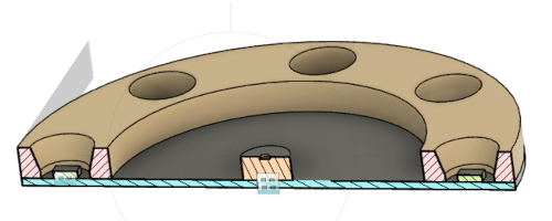
After the LEDs were placed, I drew a cylinder to the middle of the big circle, named it sensor and made a joint with the PCB (from ring to PCB). At his point I got a tip about the analysis tool. I used Inspect -> Section analysis and chose the plane for the section view to start. I positioned the view to the middle of that plane so it's shows half of the model. While working I toggle the visibility of the analysis and can check if something looks as it should.
Here is the setting up for the tool and then the result.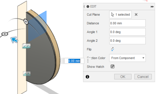
I am planning also having a casing for the whole thing, and it will be 3D printed and give a nice effect to LEDs but also add some saffety for the product. My instructor helped me to design the casing, but I am still learning about that and need to practice more before I can show that I can do it.
This first experience with Fusion360 has been very informative and fun, with of course some head ache and mistakes and quite a lot of learning. After you learn the basic stuff of just how to pick a plane and what to extrude from what and how to use the constraints, then you can get more playful with it. At first I felt like a slow giant poking my finger at all the wrong things (and using a lot of ctrl+z) but now I am starting to feel more comfortable with it. When I'm having some kind of trouble, I usually find an answer quickly from the Support and learning -section at Autodesk.
Here is the result I have been working for!